
Kubota Workshop Manual
Kubota KX61-3 and KX71-3 Workshop Manual
Document number 97899-61050 · English PDF edition · 456 pages
About this manual
Kubota published this Workshop Manual for the KX61-3 and KX71-3 excavator models. It brings the documented service and technical-reference material for those named excavators into a single publication.
The manual is especially useful for work that crosses electrical and hydraulic systems: it includes electrical troubleshooting with connector views and pinouts, alongside hydraulic diagrams, pressure-test evidence, and valve-adjustment information.
Use the Manual Contents below to check that the exact repair, inspection, or maintenance procedure you need is included in this publication.
Manual details
- Manufacturer
- Kubota
- Manual type
- Workshop Manual
- Models
- KX61-3 and KX71-3
- Document number
- 97899-61050
- Language
- English
- Page count
- 456
Product highlights
Specifications and settings
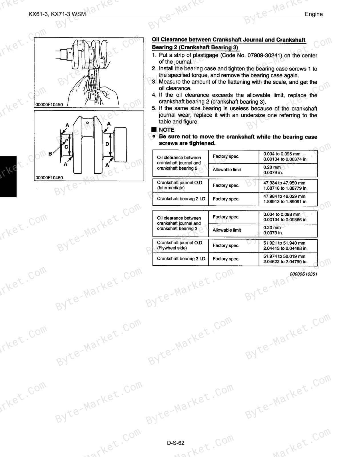
The manual includes reference information for torque specifications and pressure specifications.
Manual contents
Use these source headings to locate the task or system you need in the PDF.
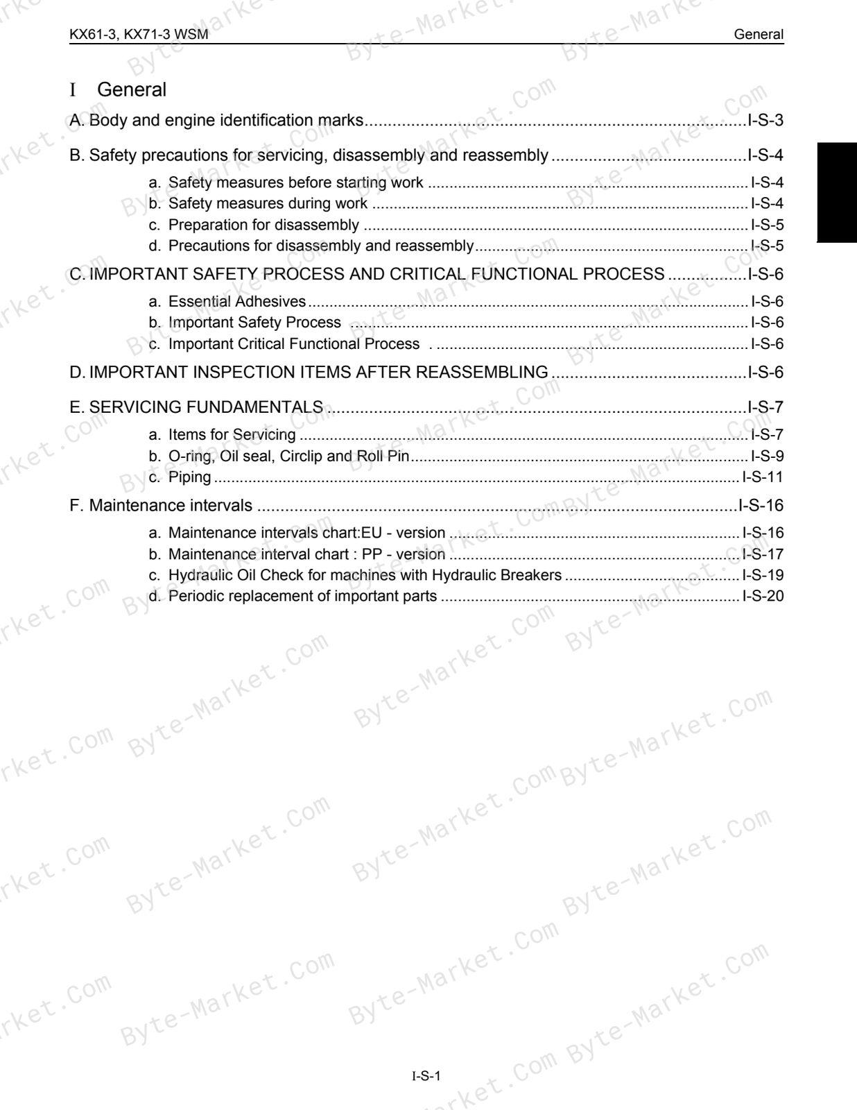
- CONTENTS — p. 2
- I General — p. 4
- A.Body and engine identification marks — p. 6
- B.Safety precautions for servicing, disassembly and reassembly — p. 7
- a. Safety measures before starting work — p. 7
- b. Safety measures during work — p. 7
- c. Preparation for disassembly — p. 8
- d. Precautions for disassembly and reassembly — p. 8
- C.IMPORTANT SAFETY PROCESS AND CRITICAL FUNCTIONAL PROCESS — p. 9
- a. Essential Adhesives — p. 9
- b. Important Safety Process . S — p. 9
- c. Important Critical Functional Process . — p. 9
- D.IMPORTANT INSPECTION ITEMS AFTER REASSEMBLING — p. 9
- E.SERVICING FUNDAMENTALS — p. 10
- a. Items for Servicing — p. 10
- b. O-ring, Oil seal, Circlip and RollPin — p. 12
- c. Piping — p. 14
- F. Maintenance intervals — p. 19
- a. Maintenance intervals chart:EU - version — p. 19
- b. Maintenance interval chart : PP - version — p. 20
- c. Hydraulic Oil Check for machines with Hydraulic Breakers — p. 22
- d. Periodic replacement of important parts — p. 23
- II. Machine body — p. 24
- A.Specifications — p. 26
- a. Machine weight — p. 26
- b. Machine specifications — p. 27
- c. Lever stroke and operating force — p. 29
- d. Dimensions of parts — p. 30
- e. Undercarriage specifications — p. 34
- f. Parts weight — p. 37
- g. Water and oil quantity — p. 39
- B.Front attachment — p. 40
- a. Parts designation — p. 40
- b. Exchange of bucket (Kubota Japan Bucket) — p. 42
- c. Exchange of bucket teeth and side cutters [JPN bucket version] — p. 43
- d. Installing direction of dust seal — p. 44
- e. Installation of thrust collar on the swing bracket — p. 44
- f. Installation of pin and bush — p. 45
- g. Grease nipple — p. 48
- h. Upper structure — p. 49
- i. Counterweight — p. 61
- C.Cab canopy installation — p. 62
- a. Installing the cabin or canopy — p. 62
- D.Under carriage — p. 82
- a. Swivel bearing — p. 82
- b. Grease tube — p. 82
- c. Track tension device — p. 83
- d. Upper roller and track roller — p. 85
- e. Crawler replacement and tension adjustment — p. 89
- A.Specifications — p. 26
- III.Engine — p. 90
- A.Specifications — p. 92
- a. Main specifications — p. 92
- B.Engine accessories;Disassembly and reassembly — p. 93
- a. Radiator fan — p. 93
- b. Radiator — p. 94
- c. Electrical parts — p. 97
- d. Engine mount — p. 98
- e. Air cleaner — p. 100
- f. Muffler — p. 101
- g. Pump coupling — p. 103
- h. Fuel tank — p. 104
- i. Fuel hoses — p. 106
- C.Engine dismounting & remounting — p. 108
- D.Engine WSM (Mechanism section) — p. 114
- A.Feature — p. 116
- B.Engine body — p. 117
- C.Lubricating system — p. 121
- D.Cooling system — p. 124
- E.Intake / exhaust system — p. 127
- F. Fuel system — p. 128
- G.Electrical system — p. 136
- D.Engine WSM (Service section) — p. 138
- A.General — p. 140
- B.Engine body — p. 169
- C.Lubricating system — p. 203
- D.Cooling system — p. 205
- E.Fuel system — p. 208
- F. Electrical system — p. 213
- A.Specifications — p. 92
- IV.Hydraulic System — p. 224
- A.Troubleshooting — p. 226
- a. Common Circuit — p. 226
- b. Hydraulic system — p. 228
- c. Pump — p. 230
- d. Motor — p. 231
- e. Swivel performance — p. 232
- f. Traveling performance — p. 238
- B.Specifications — p. 242
- a. Pump — p. 242
- b. Control valve — p. 243
- c. Swivel performance — p. 246
- d. Traveling performance — p. 247
- e. Cylinder — p. 248
- f. Motor drain amount — p. 254
- g. Service port performance — p. 255
- C.Testing — p. 256
- a. Pump flow — p. 256
- b. Pressure measurement — p. 258
- c. Drain measurement — p. 264
- d. Measurement of block performance — p. 266
- e. Operating speed — p. 267
- f. Straight travel performance — p. 269
- g. Cylinder natural fall amount — p. 269
- h. Control and traveling lever operating force — p. 269
- i. Lever stroke — p. 269
- D.Disassembling and Assembling — p. 270
- a. Preparation — p. 270
- b. Front attachment assembly — p. 270
- c. Pump — p. 273
- d. Control valve — p. 285
- e. Pilot valve — p. 304
- f. Swivel motor — p. 320
- g. Rotary joint (Swivel joint) — p. 355
- h. Traveling motor : KX71-3 PP version — p. 359
- i. Cylinder — p. 391
- j. Pilot filter — p. 396
- k. Change valve — p. 398
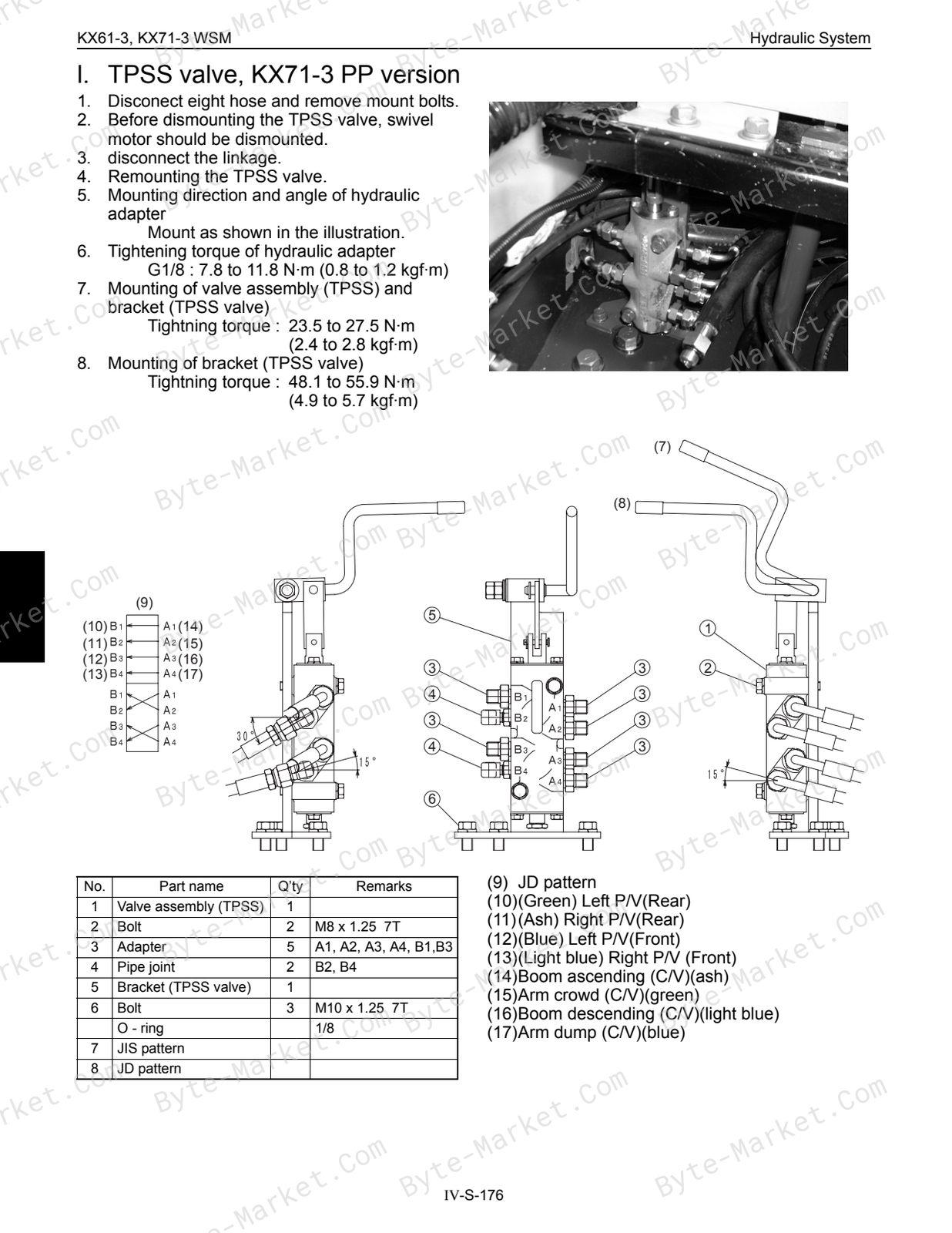
- l. TPSS valve, KX71-3 PP version — p. 399
- m.Hydraulic oil tank — p. 401
- n. Hydraulic hose — p. 404
- A.Troubleshooting — p. 226
- V. Electrical System — p. 422
- A.Specifications — p. 424
- B.Wireharness diagram and couplers — p. 426
- a. Coupler identification : KX61-3, KX71-3 — p. 426
- b. Wireharness diagram : KX61-3, KX71-3, EU - version — p. 427
- c. Wireharness diagram : KX71-3, PP - version — p. 428
- d. Functional circuit diagram — p. 429
- C.Troubleshooting & Testing — p. 430
- a. Engine — p. 430
- b. Meter panel — p. 431
- c. Others — p. 433
- d. Testing — p. 434
- D.Wire harness installation — p. 442
- a. Precautions — p. 442
- b. Engine earth, starter switch — p. 443
- c. Battery — p. 444
- d. Limit switch — p. 445
- e. Wire harness route — p. 446
- I General — p. 4
Capabilities
The source outline indexes servicing instructions, disassembly and assembly, maintenance tasks, checking and adjustment, mechanism explanations, and troubleshooting. Use these source-backed headings to locate the applicable task or system in the source PDF, then confirm model-specific notes, specifications, illustrations, and operating conditions at the relevant page before carrying out service work.
Keep the source's safety sequence, prerequisite steps, labels, units, configuration notes, and footnotes with the selected task; do not apply an isolated value outside the conditions stated in the manual.
Technical reference
Reference tables include torque settings for service checks, adjustment work, and specification lookup. Use the values and conditions in the PDF for the applicable model and procedure.
- Service limits and settings: torque settings.
Delivery
This manual is supplied as a digital PDF file and is available for instant download after purchase. No physical media is shipped.
References
Kubota Workshop Manual for Excavator, document code 97899-61050, PDF edition.


No questions found.