
Kubota Assembly Instructions
Kubota BH77 Assembly Instructions
Document number 7K503-7916-2 · English PDF edition · 70 pages
About this manual
Kubota published this Assembly Instructions for BH77. It is intended for assembly sequence, installation, setup, and source-supported adjustment, where those subjects appear in the source publication.
Use the Manual Contents below to check that the exact assembly, installation, setup, or adjustment step you need is included in this publication.
Manual details
- Manufacturer
- Kubota
- Manual type
- Assembly Instructions
- Models
- BH77
- Document number
- 7K503-7916-2
- Publication year
- 2010
- Language
- English
- Page count
- 70
Product highlights
Specifications and settings
The manual includes reference information for torque specifications.
Manual contents
Use these source headings to locate the task or system you need in the PDF.
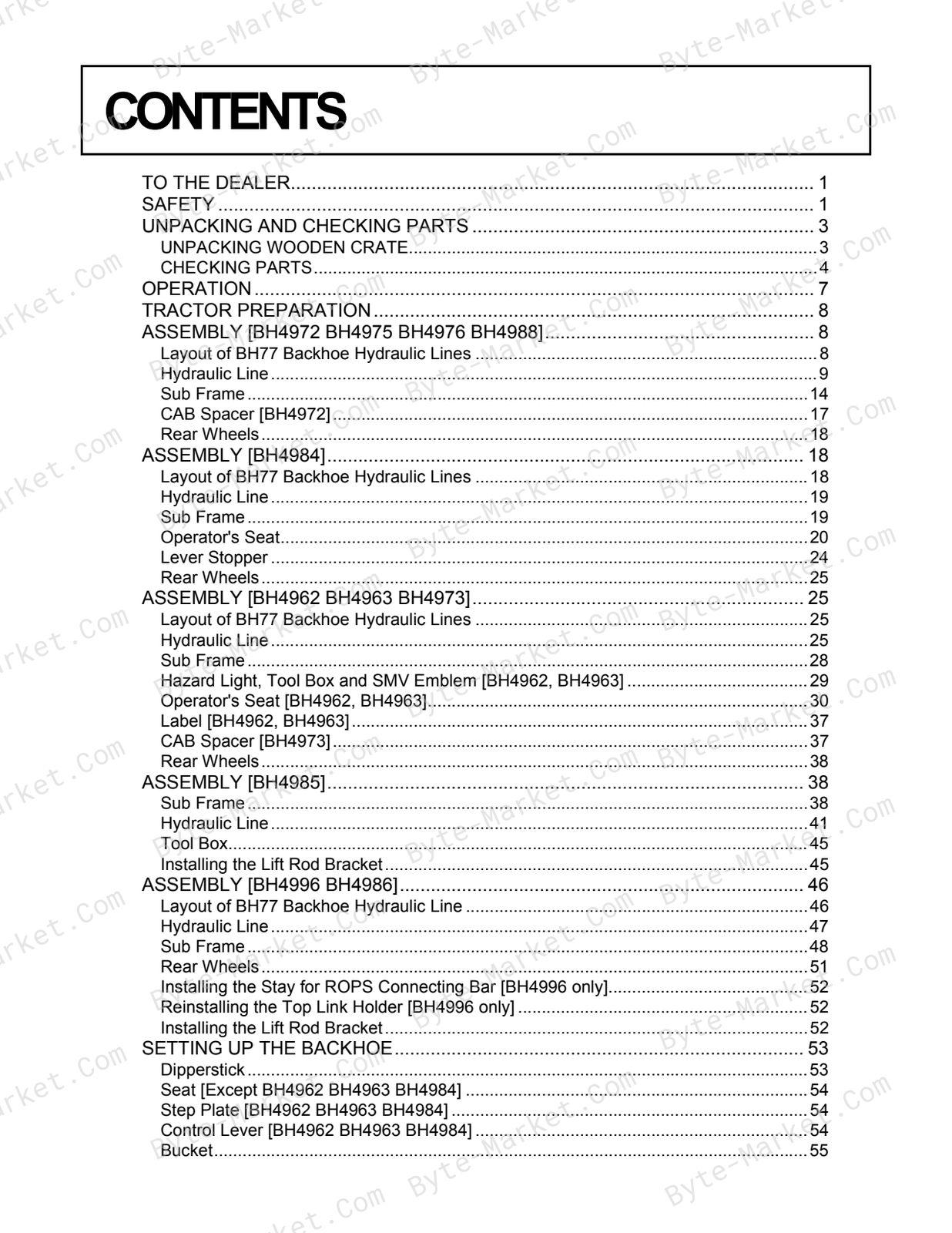
- TO THE DEALER — p. 1
- SAFETY — p. 1
- UNPACKING AND CHECKING PARTS — p. 3
- UNPACKING WOODEN CRATE — p. 3
- CHECKING PARTS — p. 4
- OPERATION — p. 7
- TRACTOR PREPARATION — p. 8
- ASSEMBLY [BH4972 BH4975 BH4976 BH4988] — p. 8
- Layout of BH77 Backhoe Hydraulic Lines — p. 8
- Hydraulic Line — p. 9
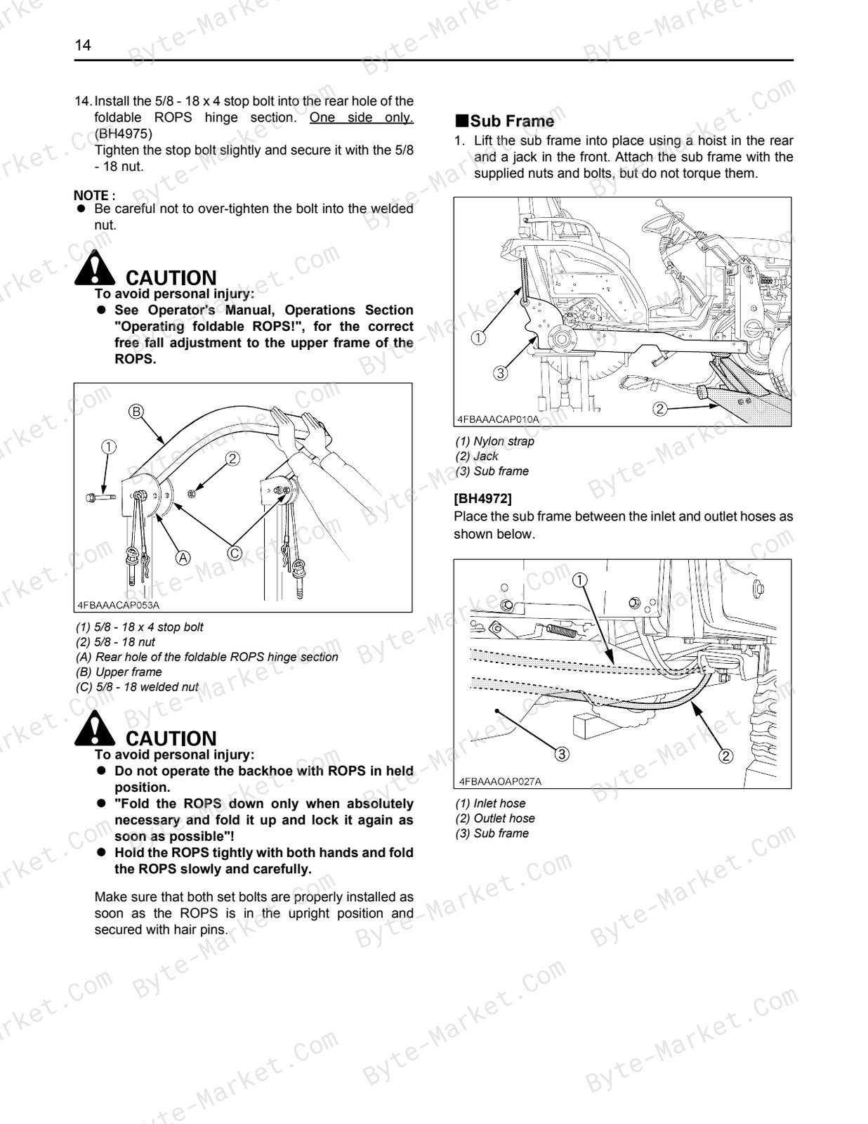
- Sub Frame — p. 14
- CAB Spacer [BH4972] — p. 17
- Rear Wheels — p. 18
- ASSEMBLY [BH4984] — p. 18
- Layout of BH77 Backhoe Hydraulic Lines — p. 18
- Hydraulic Line — p. 19
- Sub Frame — p. 19
- Operator's Seat — p. 20
- Lever Stopper — p. 24
- Rear Wheels — p. 25
- ASSEMBLY [BH4962 BH4963 BH4973] — p. 25
- Layout of BH77 Backhoe Hydraulic Lines — p. 25
- Hydraulic Line — p. 25
- Sub Frame — p. 28
- Hazard Light, Tool Box and SMV Emblem [BH4962, BH4963] — p. 29
- Operator's Seat [BH4962, BH4963] — p. 30
- Label [BH4962, BH4963] — p. 37
- CAB Spacer [BH4973] — p. 37
- Rear Wheels — p. 38
- ASSEMBLY [BH4985] — p. 38
- Sub Frame — p. 38
- Hydraulic Line — p. 41
- Tool Box — p. 45
- Installing the Lift Rod Bracket — p. 45
- ASSEMBLY [BH4996 BH4986] — p. 46
- Layout of BH77 Backhoe Hydraulic Line — p. 46
- Hydraulic Line — p. 47
- Sub Frame — p. 48
- Rear Wheels — p. 51
- Installing the Stay for ROPS Connecting Bar [BH4996 only] — p. 52
- Reinstalling the Top Link Holder [BH4996 only] — p. 52
- Installing the Lift Rod Bracket — p. 52
- SETTING UP THE BACKHOE — p. 53
- Dipperstick — p. 53
- Seat [Except BH4962 BH4963 BH4984] — p. 54
- Step Plate [BH4962 BH4963 BH4984] — p. 54
- Control Lever [BH4962 BH4963 BH4984] — p. 54
- Bucket — p. 55
- Mech. Thumb BH1976 (Option) — p. 56
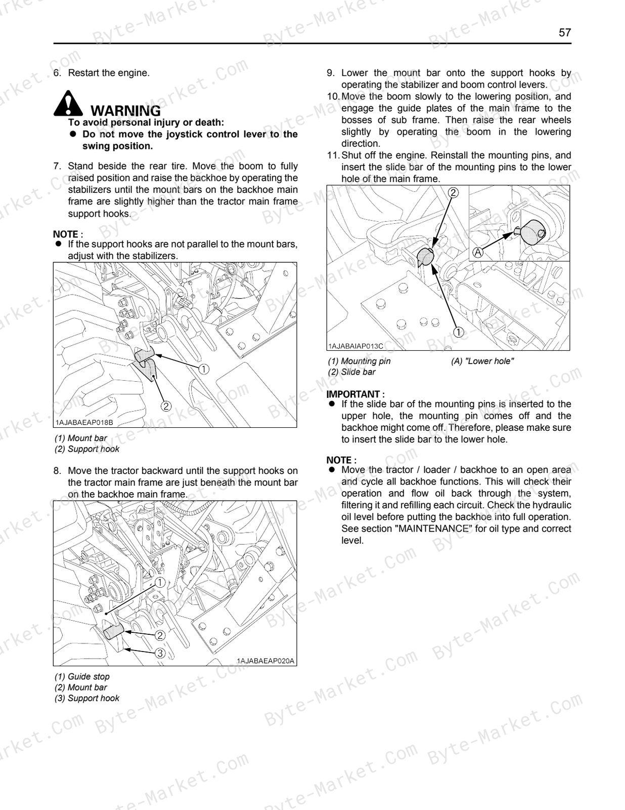
- INSTALLING THE BACKHOE — p. 56
- REMOVING THE BACKHOE — p. 58
- Removal of The Backhoe — p. 58
- Storage of The Backhoe — p. 61
- PRE-OPERATION CHECK — p. 61
- Lubrication — p. 61
- Transmission Fluid — p. 62
- ASSEMBLY TIME — p. 64
- TIGHTENING TORQUE OF BOLTS AND NUTS — p. 65
- General Torque Specification — p. 65
- TIGHTENING TORQUE OF ADAPTORS, ELBOWS AND OTHERS — p. 66
- CHECK LIST FOR INSPECTION AFTER ASSEMBLY — p. 67
Capabilities
The source outline indexes checking and adjustment, assembly, installation, connection work, and pre-operation checks. Use these source-backed headings to locate the applicable assembly or installation step in the source PDF, then confirm model-specific notes, specifications, illustrations, and operating conditions at the relevant page before carrying out installation work.
Keep the source's safety sequence, prerequisite steps, labels, units, configuration notes, and footnotes with the selected task; do not apply an isolated value outside the conditions stated in the manual.
Technical reference
Reference tables include torque settings for torques, setup checks and connection reference. Use the values and conditions in the PDF for the applicable model and procedure.
- Service limits and settings: torque settings.
Delivery
This manual is supplied as a digital PDF file and is available for instant download after purchase. No physical media is shipped.
References
Kubota Assembly Instructions for Backhoe, document code 7K503-7916-2, PDF edition.


No questions found.