
Kubota SVL97-2 Workshop Manual
Overview
This is the Kubota Workshop Manual for the SVL97-2 (document code RY911-29121, 2021 edition). It provides service and repair procedures for Kubota SVL97-2 compact track loader. Powered by the Kubota D1703, V3800 engine.
Manual Details and Coverage
- Manufacturer
- Kubota
- Models
- SVL97-2
- Equipment type
- Compact Track Loader
- Manual type
- Workshop Manual
- Document code
- RY911-29121
- Publication year
- 2021
- Language
- English
- Page count
- 588
- Format
Contents
The manual is structured as follows. Page references correspond to the original PDF pagination.
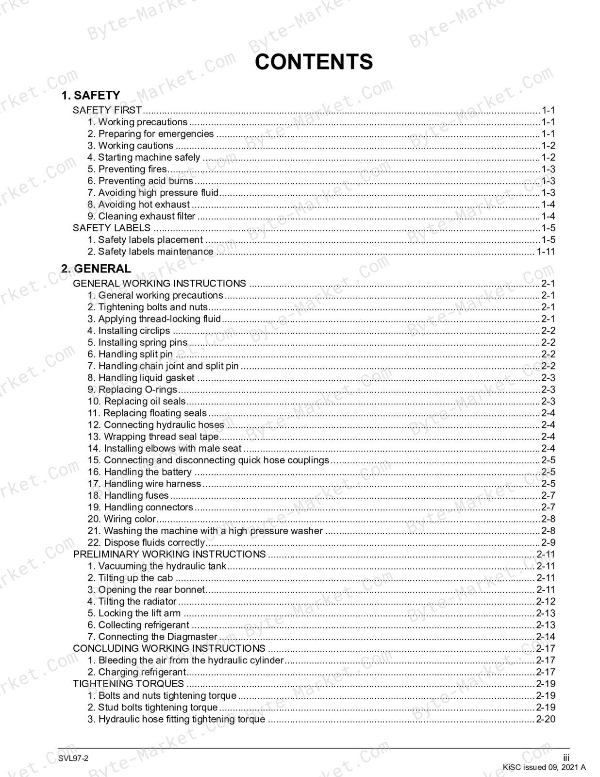
1. SAFETY
- SAFETY FIRST (1-1)
- SAFETY LABELS (1-5)
2. GENERAL
- GENERAL WORKING INSTRUCTIONS (2-1)
- PRELIMINARY WORKING INSTRUCTIONS (2-11)
- CONCLUDING WORKING INSTRUCTIONS (2-13)
- CONCLUDING WORKING INSTRUCTIONS (2-17)
- TIGHTENING TORQUES (2-19)
- GENERAL MACHINE INFORMATION (2-23)
- GENERAL ELECTRICAL INFORMATION (2-31)
- Electrical circuit diagram description (2-31)
- Electrical circuit diagram unit symbol (2-3)
- Electrical circuit diagram unit symbol (2-31)
- Electrical wiring color coding (2-32)
- Electrical wiring clamp (2-32)
- Bus description (2-33)
- Composite terminal description (2-33)
- Connector handling precaution (2-33)
- Connector diagram description (2-33)
- TRANSPORTING THE MACHINE (2-35)
- SPECIAL JIGS AND TOOLS (2-39)
3. MAINTENANCE
- MAINTENANCE INTERV
- ALS TABLE (3-1)
- LUBRICANT QUANTITY (3-5)
- RECOMMENDED LUBRICANT (3-7)
- HANDLING THE DEF/ADBLUE (3-9)
- DAILY CHECK (3-13)
- EVERY 50 HOURS (3-23)
- EVERY 250 HOURS (3-25)
- EVERY 500 HOURS (3-29)
- EVERY 1000 HOURS (3-37)
- EVERY 1500 HOURS (3-41)
- EVERY 2000 HOURS (3-45)
- EVERY 3000 HOURS (3-47)
- EVERY 8000 HOURS (3-53)
- EVERY 3 MONTHS (3-55)
- EVERY 1 YEAR (3-57)
- EVERY 2 YEARS (3-61)
- MAINTENANCE FOR A/C SPECIFICATION (3-65)
- Checking the air conditioning belt (3-65)
- Cleaning the air filters (3-65)
- Cleaning the air filters (3-65)
- Checking the condenser (3-66)
- Adjusting the air conditioning belt (3-67)
- Replacing the air filters (3-67)
- Checking the air conditioning and heater hoses (3-68)
- Replacing the air conditioning and heater hoses (3-69)
- Checking the refrigerant (3-69)
4. MACHINE BODY
- SERVICING (4-1)
- Removing/Installing cabin (4-1)
- Removing/Installing cabin (4-2)
- Collecting the refrigerant gas (4-2)
- Draining the coolant (4-2)
- Removing the cabin (4-2)
- Armrest parts drawing (4-5)
- Seat and seat belt parts drawing (4-6)
- Assembling the front window (4-6)
- Assembling window parts (4-6)
- Assembling the front window linkage (4-10)
- Assembling the front window frame (4-1)
- Front window components (4-14)
- Removing/Installing the upper window (4-16)
- Removing the upper window (4-16)
- Installing the upper window (4-16)
- Removing/Installing the rear window (4-17)
- Installing the rear window trim (4-17)
- Installing the glass for rear window (4-17)
- Removing/Installing the side window (4-18)
- Removing the side window (4-18)
- Side window parts drawing (4-19)
- Removing/Installing the lift arm / linkage (4-20)
- Removing the cabin (4-20)
- Removing the cabin (4-20)
- Installing the vacuum pump (4-20)
- Rear bonnet lock (4-20)
- Removing the lift arm (4-20)
- Removing the linkage (4-22)
- Quick hitch parts drawing (4-23)
- Mechanical quick hitch parts drawing (4-23)
- Hydraulic quick hitch parts drawing (4-24)
- Removing/Installing the accelerator pedal (4-25)
- Removing the accelerator pedal (4-25)
- Accelerator pedal parts drawing (4-25)
- Removing/Installing the rear bonnet/rear cover (4-25)
- Removing the rear bonnet (4-25)
- Collecting the refrigerant gas (4-26)
- Removing the rear cover (4-26)
- Rear bonnet parts drawing (4-28)
- Rear cover parts drawing (4-29)
- Rear cover parts drawing (Open cab model) (4-29)
- Rear cover parts drawing (Closed cab model) (4-30)
- Removing/Installing the radiator (4-31)
- Draining the coolant (4-31)
- Removing the battery (4-31)
- Installing the vacuum pump (4-32)
- Removing the radiator (4-32)
- Radiator parts drawing (4-33)
- Removing/Installing the rubber crawler (4-36)
- Removing the rubber crawlers (4-36)
- Removing the rubber crawlers (4-36)
- Rubber crawler parts drawing (4-37)
- Front idler, tension spring, and grease cylinder parts drawing (4-37)
- Front idler components (4-38)
- Tension spring components (4-38)
- Grease cylinder components (4-38)
- Track roller parts drawing (4-39)
- Track roller components (4-39)
- Rear idler parts drawing (4-40)
- Rear idler components (4-40)
- Pins, bushing and shims list (4-41)
- Assembling the front window (4-6)
5. ENGINE
- MECHANISM (5-1)
- Engine control system general description (5-9)
- Common rail system general description (5-11)
- EGR system general description (5-12)
- Supercharger system general description (5-13)
9. DPF (5-14)
- DPF general description (5-14)
- DPF output limit and warning lamp (5-15)
- SCR system general description (5-16)
- SCR output limit and warning lamp (5-17)
- Diesel Exhaust Fluid (DEF/AdBlue) level in SCR (5-17)
- DEF/AdBlue concentration and quality (5-18)
- SCR defrost control (5-19)
- DEF/AdBlue pump (Tampering) (5-20)
- SCR system error (Tampering) (5-21)
- SCR system error (Derating) (5-22)
- SERVICING (5-23)
- Removing and installing the intercooler (5-23)
- Intercooler parts drawing (5-25)
- Air cleaner parts drawing (5-27)
- Removing/Installing the SCR muffler (5-28)
- Removing and installing the intercooler (5-28)
- Removing the SCR muffler (5-29)
- Installing the SCR muffler (5-30)
- SCR muffler pipe parts drawing (5-33)
- Removing/Installing the DPF muffler (5-33)
- Removing and installing the intercooler (5-33)
- Removing the SCR muffler (5-35)
- Removing the DPF muffler (5-35)
- Removing/Installing the engine (5-37)
- Removing the cabin (5-37)
- Removing the battery (5-37)
- Draining fuel (5-38)
- Removing the radiator (5-38)
- Removal of the air cleaner (5-39)
- Removing and installing the intercooler (5-39)
- Removing the HST pump (5-41)
- Removing the SCR muffler (5-41)
- Removing the engine (5-41)
- Engine parts drawing (5-44)
- Engine mount parts drawing (5-44)
- Oil separator parts drawing (5-46)
- Muffler bracket parts drawing (5-47)
- Removing/Installing the fuel tank (5-48)
- Cabin lock (5-48)
- Draining fuel (5-48)
- Removing the step (5-48)
- Removing the fuel tank (5-49)
- Fuel tank parts drawing (5-51)
- Fuel pump parts drawing (5-52)
- Fuel hose route (5-53)
- Removing the DEF/AdBlue tank (5-54)
- DEF/AdBlue hose routing (5-54)
- DEF/AdBlue hose routing (5-56)
- DEF/AdBlue pump parts drawing (5-57)
- Coolant valve parts drawing (5-58)
- Coolant valve parts drawing (Open cab model) (5-58)
- Coolant valve parts drawing (Closed cab model) (5-58)
- Coolant valve parts drawing (Open cab model) (5-58)
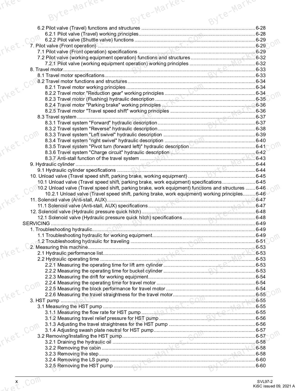
6. HYDRAULIC SYSTEM
- MECHANISM (6-1)
- HST Pump specifications (6-2)
- HST Pump functions and structures (6-3)
- HST pump working principles (6-3)
- Piston pump specifications (6-5)
- Piston pump functions (6-5)
- Piston pump functions and structures (6-6)
- Piston pump working principles (6-6)
- Piston pump "Regulator" functions and structures (6-6)
- Piston pump "Relief cut" function (6-8)
- Gear pump specifications (6-9)
- Control valve specifications (6-10)
- Control valve functions and structures (6-12)
- Control valve "Main relief valve" functions and structures (6-12)
- Control valve "LS relief valve" functions and structures (6-12)
- Control valve "Overload relief valve" functions and structures (6-13)
- Control valve "Non-operation" hydraulic description (6-14)
- Control valve "Lift arm down" hydraulic description (6-15)
- Control valve "Lift arm up" hydraulic description (6-16)
- Control valve "Bucket leveling mechanism" hydraulic description (6-17)
- Control valve "Bucket operation" hydraulic description
- Control valve "Bucket operation" hydraulic description (6-18)
- Control valve "AUX operation" hydraulic description (6-19)
- Control valve "Load Sensing (flow control)" hydraulic description (6-20)
- Control valve "Anti-Saturation" hydraulic description (6-23)
- Control valve "Lift arm float operation" hydraulic description (6-24)
- Control valve "Hydraulic quick hitch" hydraulic description (6-25)
- Pilot valve (Travel) specifications (6-26)
- Pilot valve (Travel) functions and structures (6-28)
- Pilot valve (Travel) working principles (6-28)
- Pilot valve (Shuttle valve) functions (6-29)
- Pilot valve (Front operation) specifications (6-29)
- Pilot valve (working equipment operation) functions and structures (6-32)
- Pilot valve (working equipment operation) working principles (6-32)
- Travel motor specifications (6-33)
- Travel motor functions and structures (6-34)
- Travel motor working principles (6-34)
- Travel motor "Reduction gear" working principles (6-34)
- Travel motor (Flushing) hydraulic description (6-35)
- Travel motor "Parking brake" working principles (6-36)
- Travel motor "Travel speed shift" working principles (6-36)
- Travel system (6-37)
- Travel system "Forward" hydraulic description (6-37)
- Travel system "Reverse" hydraulic description (6-38)
- Travel system "Left swivel" hydraulic descriptio
- Travel system "Left swivel" hydraulic description (6-39)
- Travel system "right swivel" hydraulic description (6-40)
- Travel system "Pivot turn (forward left)" hydraulic description (6-41)
- Travel system "Charge circuit" hydraulic description (6-42)
- Anti-stall function of the travel system (6-43)
- Hydraulic cylinder specifications (6-44)
- Unload valve (Travel speed shift, parking brake, work equipment) specifications (6-45)
- Unload valve (Travel speed shift, parking brake, work equipment) functions and structures (6-46)
- Unload valve (Travel speed shift, parking brake, work equipment) working principles (6-46)
- Solenoid valve (Anti-stall, AUX) specifications (6-47)
- Solenoid valve (Hydraulic pressure quick hitch) specifications (6-48)
- Pilot valve (Travel) working principles (6-28)
- SERVICING (6-49)
- Troubleshooting hydraulic for working equipment (6-49)
- Troubleshooting hydraulic for traveling (6-51)
- Hydraulic performance list (6-53)
- Hydraulic operating time (6-53)
- Measuring the operating time for lift arm cylinder (6-53)
- Measuring the operating time for bucket cylinder (6-53)
- Measuring the drift for working equipment (6-54)
- Measuring the operating time for travel motor (6-54)
- Measuring the block performance for travel motor (6-54)
- Measuring the travel straightness for the travel motor (6-55)
- Measuring the HST pump (6-55)
- Measuring the flow rate for HST pump (6-55)
- Measuring travel relief pressure for HST pump (6-56)
- Adjusting the travel straightness for the HST pump (6-56)
- Adjusting swash plate neut (6-55)
- Adjusting swash plate neutral for HST pump (6-57)
- Removing/Installing the HST pump (6-57)
- Draining the hydraulic oil (6-58)
- Removing the cabin (6-58)
- Removing the step (6-58)
- Removing the LS pump (6-60)
- Removing the HST pump (6-60)
- Disassembling the HST pump (6-61)
- Disassembling the shaft assembly (6-61)
- Disassembling the cylinder block (6-63)
- Disassembling the relief valve (6-64)
- Disassembling the servo piston (6-64)
- Assembling the HST pump (6-66)
- Assembling the servo cylinder (6-66)
- Assembling the relief valve (6-68)
- Assembling the cylinder block (Engine side) (6-69)
- Assembling the shaft (Engine side) (6-71)
- Assembling the cylinder block (Pump side) (6-73)
- Assembling the the shaft (Pump side) (6-73)
- Assembling the adapter (6-75)
- HST pump components (6-76)
- Installing adapter layout for HST pump (6-80)
- Pump coupling parts drawing (6-81)
- Measuring the piston pump (6-82)
- Mea
- Measuring the flow rate for piston pump (6-82)
- Bleeding air from the piston pump (6-82)
- Removing/Installing the piston pump (6-83)
- Removing the cabin (6-83)
- Removing the step (6-83)
- Installing the vacuum pump (6-85)
- Removing the piston pump (6-85)
- Disassembling the piston pump (6-85)
- Removing the gear pump (6-86)
- Removing the valve cover (6-86)
- Removing internal parts for piston pump (6-87)
- Disassembling the regulator for piston pump (6-88)
- Assembling the piston pump (6-89)
- Assembling the regulator for piston pump (6-89)
- Assembling internal parts for piston pump (6-89)
- Assembling valve cover for piston pump (6-92)
- Assembling the gear pump (6-89)
- Assembling the gear pump (6-93)
- Piston pump components (6-94)
- Installing adapter layout for piston pump (6-96)
- Servicing standards of piston pump (6-97)
- Measuring the piston clearance (6-97)
- Measuring the play for shoe crimping section (6-97)
- Measuring shoe thickness (6-97)
- Measuring the length for cylinder spring (6-98)
- Measuring the sinkage for spherical bushing (6-98)
- Measuring the control valve (6-98)
- Measuring the unload LS valve (6-98)
- Measuring the LS relief valve (6-99)
- Measuring the overload relief valve (6-99)
- Adjusting the flow dividing valve (6-100)
- Removing/Installing the control valve (6-100)
- Removing the cab
- Removing the cabin (6-101)
- Installing the vacuum pump (6-101)
- Removing/Installing the control valve (6-101)
- Disassembling the control valve (6-102)
- Removing the section for control valve (6-102)
- Removing the flow divider section for the control valve (6-104)
- Removing the relief valve for the control valve (6-105)
- Removing the float solenoid valve for the control valve (6-107)
- Assembling the control valve (6-108)
- Assembling the section for control valve 6-
- Assembling the flow divider section for control valve (6-110)
- Assembling the relief valve for the control valve (6-112)
- Assembling the float solenoid valve for the control valve (6-114)
- Control valve components (6-116)
- Installing adapter layout for control valve (6-119)
- Removing/Installing the travel motor (6-121)
- Removing/Installing the rubber crawler (6-121)
- Installing the vacuum pump (6-121)
- Removing the travel motor (6-121)
- Removing/Installing the rubber crawler (6-121)
- Disassembling the travel motor (6-122)
- Disassembling the gear case for travel motor (6-122)
- Disassembling the hydraulic motor for the travel motor (6-125)
- Disassembling the gear case for travel motor (6-122)
- Assembling the travel motor (6-128)
- Assembling the gear case for travel motor (6-128)
- Assembly of travel motor (6-133)
- Assembling the gear case for travel motor (6-128)
- Travel motor components
- Travel motor components (6-139)
- Installing adapter layout for travel motor (6-141)
- Measuring the piston pump (6-141)
- Measuring pressure for pilot valve (6-141)
- Measuring pressure for the pilot valve (Lift arm, bucket) (6-142)
- Disassembling the pilot valve (6-142)
- Removing the reducing valve (6-143)
- Disassembling the reducing valve (6-144)
- Assembling the pilot valve (6-145)
- Assembling the reducing valve (6-145)
- Assembling the pilot valve (6-146)
- Pilot valve components (6-148)
- Disassembling/Installing the lift arm cylinder (6-149)
- Removing the lift arm (6-149)
- Removing the battery (6-149)
- Removing the lift arm cylinder (6-149)
- Disassembling the lift arm cylinder (6-150)
- Disassembling the cylinder rod for lift arm cylinder (6-150)
- Disassembling the cylinder head for lift arm cylinder (6-152)
- Assembling the lift arm cylinder (6-153)
- Assembling the cylinder head for lift arm cylinder (6-153)
- Assembling the cylinder rod for lift arm cylinder (6-154)
- Servicing standards for hydraulic cylinder (6-157)
- Measuring the bend for cylinder rod (6-157)
- Measuring the wear for cylinder rod and cylinder head (6-158)
- Measuring the wear for the cylinder tube and piston wear ring (6-158)
- Lift arm cylinder components (6-159)
- Removing/Installing the bucket cylinder (6-160)
- Removing the bucket cylinder (6-160)
- Bucket cylinder components
- Bucket cylinder components (6-162)
- Removing/Installing the hydraulic quick hitch cylinder (6-163)
- Removing the quick hitch cylinder (6-163)
- Hydraulic quick hitch cylinder components (6-163)
- Removing/Installing the unload valve (6-164)
- Installing the vacuum pump (6-164)
- Cabin lock (6-164)
- Removing the unload valve (6-164)
- Installing adapter layout for unload valve (6-166)
- Disassembly/Assembly of solenoid valves (Anti-stall, AUX) (6-167)
- Installing the vacuum pump (6-167)
- Cabin lock (6-167)
- Removal of solenoid valve (Anti-stall, AUX) (6-167)
- Installing adapter layout for solenoid valve (Anti-stall, AUX) (6-168)
- Installing adapter layout for solenoid valve (Hydraulic quick hitch) (6-168)
- Removing/Installing the hydraulic oil tank (6-168)
- Draining the hydraulic oil (6-168)
- Cabin lock (6-169)
- Removing the step (6-169)
- Removing the LS pump (6-171)
- Removing the hydraulic oil tank (6-171)
- Hydraulic (6-169)
- Hydraulic oil tank components (6-173)
- Installing adapter layout for hydraulic oil tank (6-175)
- Total length for hydraulic hoses (6-176)
- Hydraulic hose fittings (6-176)
- Hose route (6-177)
- Piston pump (6-177)
- HST pump, HST filter (6-179)
- Control valve (6-181)
- Bucket cylinder (6-184)
- Unload valve (6-185)
- AUX solenoid valve (6-187)
- Relay, pilot valve (6-189)
- Quick hitch model (6-191)
- Measuring the piston pump (6-141)
7. ELECTRICAL SYSTEM
- MECHANISM (7-1)
- Layout of electrical device (7-1)
- Meter panel display (7-4)
- Lamps (7-5)
- Buzzer (7-5)
- Meter panel functions (7-6)
- Normal mode (7-6)
- Normal mode display (7-6)
- User settings mode (7-7)
- AUX flow rate setting in user setting mode (7-7)
- Service mode (7-8)
- Service mode settings list (7-8)
- SERVICING (7-9)
- Troubleshooting electrical (7-9)
- Error warning list (7-9)
- Engine error warning list (7-11)
- E:001 CAN communication error (7-13)
- Checking on the meter panel for E:001 CAN communication error (7-13)
- Checking on the meter panel for E:001 CAN communication error (7-13)
- Checking with circuit tester for E:001 CAN communication error (7-14)
- E:005 High hydraulic oil temperature (7-14)
- Checking on the meter panel for E:005 high hydraulic oil temperature
- Checking devices for E:005 high hydraulic oil temperature (7-14)
- E:008 Fuel sensor error (7-15)
- Checking on the meter panel for E:008 fuel sensor error (7-15)
- Checking devices for E:008 fuel sensor error (7-15)
- Checking circuit tester for E:008 fuel sensor error (7-16)
- E:009 Accelerator dial sensor (Break or short) (7-17)
- Checking on the meter panel for E:009 accelerator sensor error (7-17)
- Checking devices for E:009 accelerator sensor error (7-18)
- Checking with circuit tester for E:009 Accelerator sensor error (7-18)
- E:010 Travel speed shift solenoid error (7-19)
- Checking on the meter panel for E:010 travel speed shift solenoid error (7-19)
- Checking devices for E:010 travel speed shift solenoid error (7-20)
- Checking with circuit tester for E:010 travel speed shift solenoid error (7-20)
- E:011 Parking brake solenoid error (7-22)
- Checking on the meter panel for E:011 parking brake solenoid error (7-22)
- Checking devices for E:011 parking brake solenoid error (7-22)
- Checking with circuit tester for E:011 parking brake solenoid error (7-23)
- E:012 Float solenoid error
- E:012 Float solenoid error (7-24)
- Checking on the meter panel for E:012 float solenoid error (7-24)
- Checking devices for E:012 float solenoid error (7-25)
- Checking with circuit tester for E:012 float solenoid error (7-25)
- E:013 Hydraulic lock release solenoid error (7-27)
- Checking on the meter panel for E:013 hydraulic lock release solenoid error (7-27)
- Checking devices for E:013 hydraulic lock release solenoid error (7-27)
- Checking with circuit tester for E:013 hydraulic lock release solenoid error (7-28)
- E:014 Low hydraulic oil temperature error (7-30)
- Checking on the meter panel for E:014 low hydraulic oil temperature (7-30)
- Checking devices for E:014 low hydraulic oil temperature error (7-30)
- Checking with circuit tester for E:014 low hydraulic oil temperature error (7-31)
- E:015 Hydraulic hitch solenoid error (7-32)
- Checking on the meter panel for E:015 hydraulic hitch solenoid error (7-32)
- Checking devices for E:015 hydraulic hitch solenoid error (7-32)
- Checking with circuit tester for E:015 hydraulic hitch solenoid error (7-33)
- E:016 AUX knob-switch error (7-35)
- Checking on the meter panel for E:016 AUX knob-switch error (7-35)
- Checking devices for E:016 AUX knob-switch error (7-35)
- Checking devices for E:016 AUX knob-switch error (7-35)
- Checking with the circuit tester for E:016 AUX knob-switch error (7-35)
- E:018 AUX right solenoid error (7-36)
- Checking on the meter panel for E:018 AUX right solenoid error (7-36)
- Checking devices for E:018 AUX right solenoid error (7-37)
- Checking with circuit tester for E:018 AUX right solenoid error (7-37)
- E:019 AUX left solenoid error (7-38)
- Checking on the meter panel for E:019 AUX left solenoid error (7-38)
- Checking devices for E:019 AUX left solenoid error (7-39)
- Checking with circuit tester for E:019 AUX left solenoid error (7-39)
- E:020 Anti-stall solenoid error (7-40)
- Checking on the meter panel for E:020 Anti-stall solenoid error (7-40)
- Checking devices for E:020 Anti-stall solenoid error (7-41)
- Checking with circuit tester for E:020 Anti-stall solenoid error (7-41)
- E:021 5 V error (7-42)
- Checking on the meter panel for E:021 5 V error (7-42)
- Checking devices for E:021 5 V error (7-42)
- Checking external 5 V short with a circuit tester (7-42)
- Checking external 5 V short with a circuit tester (7-44)
- E:023 Overvoltage (7-47)
- Checking on the meter panel for E:023 overvoltage (7-47)
- Checking devices for E:023 overvoltage (7-47)
- Checking with circuit tester for E:023 overvoltage (7-47)
- E:024 Hydraulic oil temperature sensor error (7-48)
- Checking on the meter panel for E:024 hydraulic oil temperature sensor error
- Checking devices for E:024 hydraulic oil temperature sensor error (7-48)
- Checking with circuit tester for E:024 hydraulic oil temperature sensor error (7-48)
- E:026 CRS CAN communication error (7-50)
- Checking on the meter panel for E:026 CRS CAN communication error (7-50)
- Checking devices for E:026 CRS CAN communication error (7-50)
- Checking with circuit tester for E:026 CRS CAN communication error (7-52)
- E:027 ACU CAN communication error (7-52)
- Check on the meter panel for E:027 ACU CAN communication error (7-52)
- Checking devices for E:027 ACU CAN communication error (7-53)
- Check with circuit tester for E:027 ACU CAN communication error (7-55)
- E:028 Foot accelerator sensor error (7-55)
- Checking on the meter panel for E:028 foot accelerator sensor error (7-55)
- Checking devices for E:028 foot accelerator sensor error (7-56)
- Checking with circuit tester for E:028 foot accelerator sensor error (7-56)
- E:9116 Engine overheating (7-58)
- Checking on the meter panel for E:9116 Engine overheating (7-58)
- Checking devices for E:9116 engine overheating (7-58)
- E:9118 Engine oil pressure error
- E:9118 Engine oil pressure error (7-58)
- Checking on the meter panel for E:9118 engine oil pressure error (7-58)
- Checking devices for E:9118 engine oil pressure error (7-59)
- Checking with circuit tester for E:9118 engine oil pressure error (7-60)
- E:9119 Battery charging error (7-61)
- Checking on the meter panel for E:9119 battery charging error (7-61)
- Checking devices for E:9119 battery charging error (7-61)
- Checking with circuit tester for E:9119 battery charging error (7-61)
- E:9120 Water separator error (7-62)
- Checking on the meter panel for E:9120 water separator error (7-62)
- Checking devices for E:9120 water separator error (7-62)
- Checking with circuit tester for E:9120 water separator error (7-63)
- E:9126 CCV pressure error (7-63)
- Checking on the meter panel for E:9126 CCV pressure error (7-63)
- Checking devices for E:9126 CCV pressure error (7-63)
- Checking with circuit tester for E:9126 CCV pressure error (7-64)
- E:9127 Continuous CCV pressure error (7-66)
- Checking on the meter panel for E:9127 continuous CCV pressure error (7-66)
- Meter panel switches operation (7-66)
- AUX flow rate setting (7-67)
- Service mode operations (7-67)
- No-01 Tester mode (7-68)
- No-02 AUX knob setting (7-71)
- No-03 AUX start-up point setting (7-71)
- No-04 AUX current fine setting (7-72)
- No-05 HST start-up point setting (7-73)
- No-07 Accelerator pedal/dial setting (7-74)
- No-09 Read error history (7-74)
- No-10 Clear error history (7-74)
- No-11 Read all error history (7-75)
- No-12 AUX flow rate adjustment (7-75)
- MECHANISM (8-1)
- Air conditioning equipments layout (8-1)
- Air conditioning system general description (8-3)
- Compressor specifications (8-4)
- Compressor functions and structures (8-5)
- Magnetic clutch functions and structures (8-5)
- Safety valve functions and structures (8-6)
- Temperature sensor functions and structures (8-6)
- Compressor oil functions and structures (8-6)
- Air conditioning specifications (8-7)
- Evaporator functions and structures (8-8)
- Heater core functions and structures (8-8)
- Blower motor functions and structures (8-8)
- Blower resistor functions and structures (8-9)
- Expansion valve functions and structures (8-9)
- Fin thermistor functions and structures (8-10)
- Hot water valve functions and structures (8-10)
- Condenser specifications (8-10)
- Condenser specifications (8-11)
- Condenser functions and structures (8-11)
- Receiver specifications (8-11)
- Receiver functions and structures (8-12)
- Pressure switch specifications (8-12)
- Pressure switch functions and structures (8-13)
- SERVICING (8-15)
- Troubleshooting the air conditioning system (8-15)
- Troubleshooting the compressor (8-17)
- Checking the fuses (8-17)
- Checking the relays (8-18)
- Checking the air conditioning control panel (8-19)
- Measuring and checking the compressor (8-20)
- Removing/Installing the compressor (8-21)
- Oil amount in the compressor (8-22)
- Measuring and checking the air conditioning unit (8-23)
- Measuring and checking the blower motor (8-23)
- Measuring and checking the blower resistor (8-23)
- Removing/Installing the air conditioning unit (8-24)
- Air conditioning unit parts drawing (8-26)
- Measuring and checking the condenser (8-26)
- Measuring and checking the condenser fan motor (8-26)
- Measuring and checking the condenser fan motor (8-26)
- Measuring and checking the condenser fan motor (8-26)
- Removing/Installing the condenser and the receiver (8-27)
- Removing/Installing the air conditioning hose (8-29)
- Removing/Installing the heater hose (8-30)
- ABBREVIATIONS
- DANGER
- WARNING
- CAUTION
- IMPORTANT
- SVL97-2
- 1-2 SVL97-2
- SVL97-2
- 1-4 SVL97-2
- SAFETY LABELS
- SVL97-2
- 1-6 SVL97-2
- SVL97-2
- 1-8 SVL97-2
- SVL97-2
- 1-10 SVL97-2
- SVL97-2
- GENERAL WORKING INSTRUCTIONS
- • T
- SVL97-2
- 2-2 SVL97-2
- in.) without making any gaps
- in.)
- in.)
- SVL97-2
- 2-4 SVL97-2
- SVL97-2
- 2-6 SVL97-2
- SVL97-2
- • W
- 2-8 SVL97-2
Delivery (Instant Download)
This manual is supplied as a digital PDF file and is available for instant download after purchase. No physical media is shipped.
References
Kubota Workshop Manual for Compact Track Loader, document code RY911-29121, PDF edition.


No questions found.