
Kubota Workshop Manual
Kubota BX1870, BX2370, BX2670, RCK48-18BX, RCK54-23BX, RCK60B-23BX, RCK48P-18BX, RCK54P-23BX, LA203A, and LA243A Workshop Manual
Document number 9Y111-08550 · English PDF edition · 107 pages
About this manual
Kubota published this Workshop Manual for the BX1870, BX2370, BX2670, RCK48-18BX, RCK54-23BX, RCK60B-23BX, RCK48P-18BX, RCK54P-23BX, LA203A, and LA243A tractor models. It brings the documented service and technical-reference material for those named tractors into a single publication.
Use the Manual Contents below to check that the exact repair, inspection, or maintenance procedure you need is included in this publication.
Manual details
- Manufacturer
- Kubota
- Manual type
- Workshop Manual
- Models
- BX1870, BX2370, BX2670, RCK48-18BX, RCK54-23BX, RCK60B-23BX, RCK48P-18BX, RCK54P-23BX, LA203A, and LA243A
- Document number
- 9Y111-08550
- Publication year
- 2012
- Language
- English
- Page count
- 107
Product highlights
Electrical systems
The manual includes wiring diagrams.
Special tools
A special-tools section is included.
Manual contents
Use these source headings to locate the task or system you need in the PDF.
- 1. WIRING DIAGRAM — p. 6-M1
- 2. STARTING SYSTEM — p. 6-M2
- [1] MAIN SWITCH POSITION — p. 6-M2
- [2] SAFETY SWITCH — p. 6-M3
- [3] OPERATOR PRESENCE CONTROL (OPC) — p. 6-M4
- 3. CHARGING SYSTEM — p. 6-M5
- [1] ELECTRICAL CIRCUIT — p. 6-M5
- [2] IC REGULATOR (3P CONNECTOR TYPE) — p. 6-M6
- 4. LIGHTING SYSTEM — p. 6-M7
- 5. GAUGES — p. 6-M8
- [1] ELECTRICAL CIRCUIT — p. 6-M8
- [2] HOUR AND TACHOMETER — p. 6-M9
- [3] FUEL LEVEL GAUGE — p. 6-M9
- [4] WATER TEMPERATURE GAUGE — p. 6-M10
- OTHERS — p. 6-M11
- [1] DC OUTLET — p. 6-M11
- 1. TROUBLESHOOTING — p. 6-S1
- 2. SERVICING SPECIFICATIONS — p. 6-S5
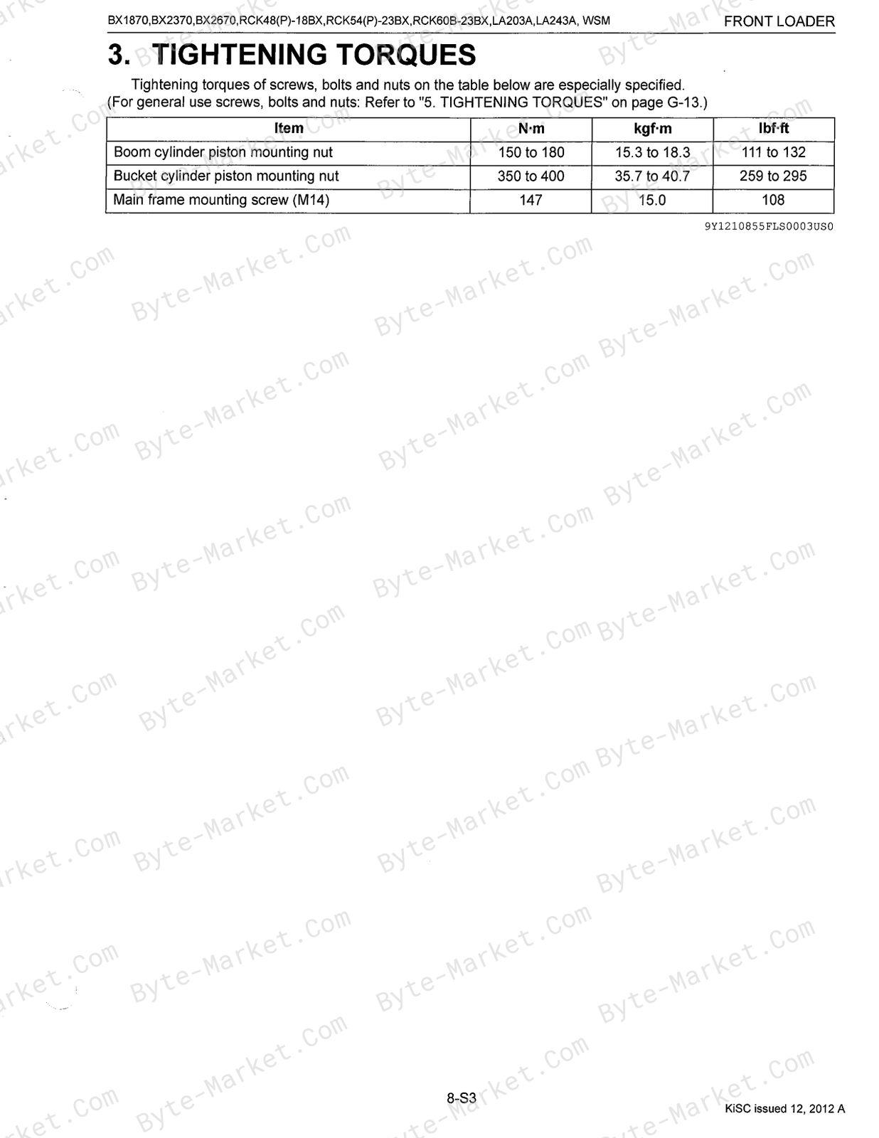
- 3. TIGHTENING TORQUES — p. 6-S6
- 4. CHECKING, DISASSEMBLING AND SERVICING — p. 6-S7
- [1] CHECKING AND ADJUSTING — p. 6-S7
- (1) Battery — p. 6-S7
- (2) Main Switch — p. 6-S9
- (3) Starter — p. 6-S10
- (4) Glow Plug — p. 6-S11
- (5) Safety Switch — p. 6-S12
- (6) Operator Presence Control (OPC) Switch — p. 6-S14
- (7) Fuel Pump — p. 6-S15
- (8) Engine Stop Solenoid — p. 6-S16
- (9) Timer Relay — p. 6-S16
- (10) Charging System — p. 6-S17
- (11) Combination Switch — p. 6-S17
- (12) Gauge — p. 6-S23
- (13) DC Outlet — p. 6-S25
- (14) Meter Panel — p. 6-S25
- [2] DISASSEMBLING AND ASSEMBLING — p. 6-S28
- (1) Starter — p. 6-S28
- (2) Alternator — p. 6-S29
- [3] SERVICING — p. 6-S31
- (1) Starter — p. 6-S31
- (2) Alternator — p. 6-S33
- [1] CHECKING AND ADJUSTING — p. 6-S7
- 1. POWER TRANSMISSION — p. 7-M1
- 2. LIFTING MECHANISM — p. 7-M2
- 3. SELF-BALANCER SYSTEM — p. 7-M3
- 1. HYDRAULIC CIRCUIT SCHEMATIC — p. 8-M1
- 2. CONTROL VALVE ASSEMBLY — p. 8-M2
- 3. BOOM CYLINDER AND BUCKET CYLINDER — p. 8-M3
- 1. TROUBLESHOOTING — p. 8-S1
- 2. SERVICING SPECIFICATIONS — p. 8-S2
- 3. TIGHTENING TORQUES — p. 8-S3
- 4. DISASSEMBLING AND SERVICING — p. 8-S4
- [1] DISMOUNTING AND MOUNTING FRONT LOADER — p. 8-S4
- (1) Dismounting Front Loader From Tractor — p. 8-S4
- (2) Mounting Front Loader to Tractor — p. 8-S5
- [2] FRONT LOADER — p. 8-S6
- (1) Bucket, Boom and Hydraulic Cylinders — p. 8-S6
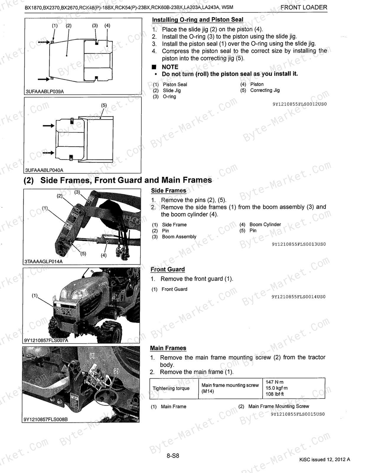
- (2) Side Frames, Front Guard and Main Frames — p. 8-S8
- [3] SERVICING — p. 8-S9
- [1] DISMOUNTING AND MOUNTING FRONT LOADER — p. 8-S4
Capabilities
The source outline indexes troubleshooting, servicing instructions, checking and adjustment, disassembly and assembly, and mechanism explanations. Use these source-backed headings to locate the applicable task or system in the source PDF, then confirm model-specific notes, specifications, illustrations, and operating conditions at the relevant page before carrying out service work.
Keep the source's safety sequence, prerequisite steps, labels, units, configuration notes, and footnotes with the selected task; do not apply an isolated value outside the conditions stated in the manual.
Delivery
This manual is supplied as a digital PDF file and is available for instant download after purchase. No physical media is shipped.
References
Kubota Workshop Manual for Tractor, document code 9Y111-08550, PDF edition.


No questions found.