
Kubota KX019-4 LPG Workshop Manual
Overview
This is the Kubota Workshop Manual for the KX019-4 (document code RY911-29401, 2022 edition). It provides service and repair procedures for Kubota KX019-4 excavator.
Models and Coverage
- Models: KX019-4
- Equipment type: Excavator
- Applicability: Kubota KX019-4 series excavators
- Document code: RY911-29401
- Year: 2022
Document Details
- Manufacturer
- KUBOTA
- Manual type
- Workshop Manual
- Models
- KX019-4
- Document code
- RY911-29401
- Year
- 2022
- Language
- English
- Page count
- 238
- Format
Contents
The manual is structured as follows. Page references correspond to the original PDF pagination.
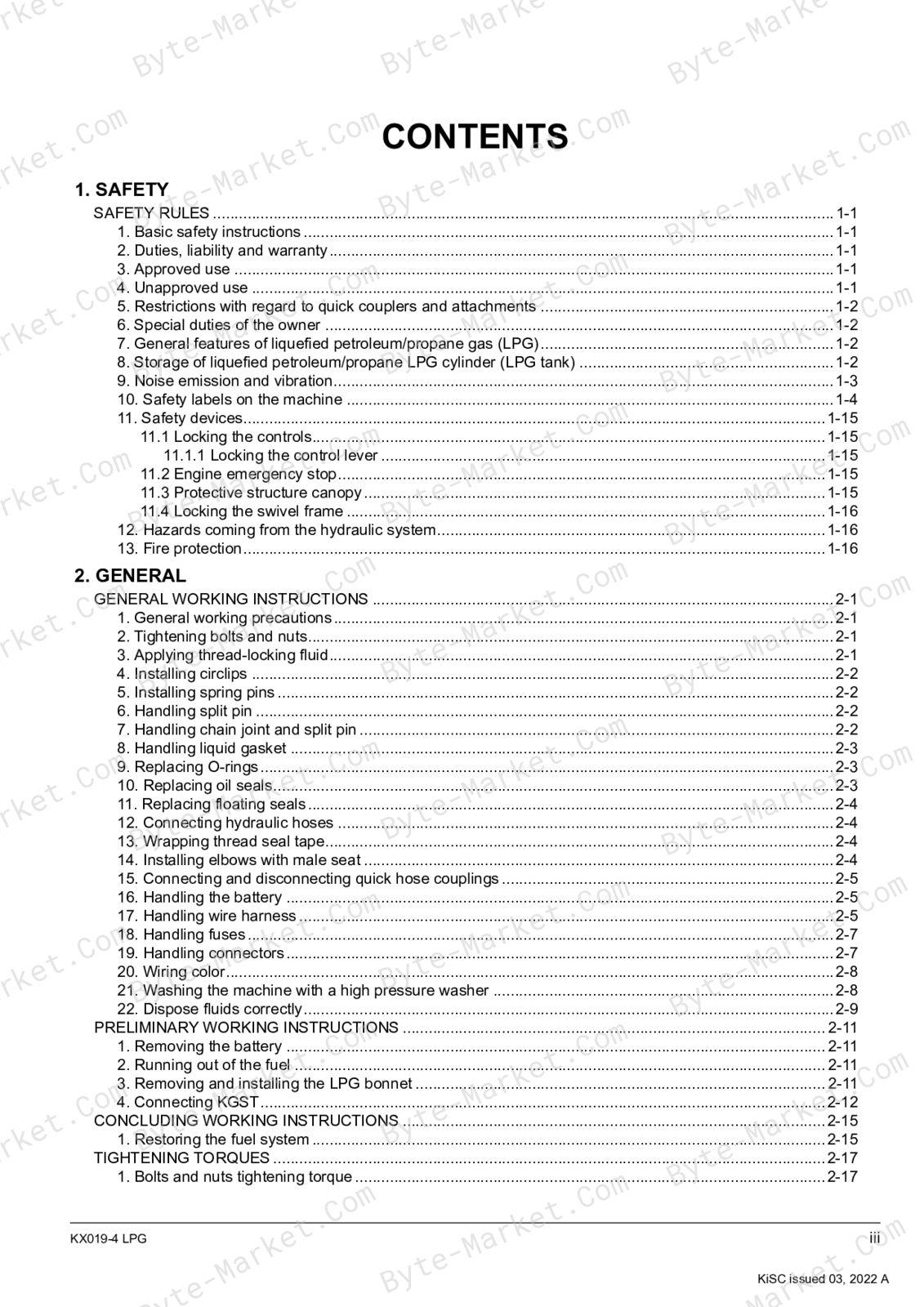
1. SAFETY
- SAFETY RULES (1-1)
- Locking the controls (1-15)
- Locking the control lever (1-15)
- Engine emergency stop (1-15)
- Protective structure canopy (1-15)
- Locking the swivel frame (1-15)
- Locking the swivel frame (1-16)
- Locking the controls (1-15)
2. GENERAL
- GENERAL WORKING INSTRUCTIONS (2-1)
- PRELIMINARY WORKING INSTRUCTIONS (2-11)
- CONCLUDING WORKING INSTRUCTIONS (2-15)
- TIGHTENING TORQUES (2-17)
- GENERAL MACHINE INFORMATION (2-21)
- GENERAL ELECTRICAL INFORMATION (2-27)
- Electrical circuit diagram description (2-27)
- Electrical circuit diagram unit symbol (2-27)
- Electrical wiring color coding (2-28)
- Electrical wiring clamp (2-28)
- Bus descript
- Bus description (2-29)
- Composite terminal description (2-29)
- Connector handling precaution (2-29)
- Connector diagram description (2-29)
- TRANSPORTING THE MACHINE (2-31)
- SPECIAL JIGS AND TOOLS (2-33)
3. MAINTENANCE
- MAINTENANCE INTERVALS TABLE (3-1)
- LUBRICANT QUANTITY (3-7)
- RECOMMENDED LUBRICANTS (3-9)
- RECOMMENDED LPG CYLINDER DIMENSIONS (3-11)
- DAILY CHECK (3-13)
- Chec
- Checking and setting the LPG cylinder (3-13)
- Checking the exhaust system leakage (3-13)
- Checking the fuel level (3-14)
- Checking the fuel line connections (3-15)
- EVERY 50 HOURS (3-17)
- Checking the fuel line leakage (3-17)
- EVERY 200 HOURS (3-19)
- Checking the intake air line hoses (3-19)
- Checking the regulator hose and vaporizer hose (3-19)
- EVERY 250 HOURS (3-21)
- Cleaning and adjusting the spark plug (3-21)
- Checking the fuel line hoses (3-21)
- EVERY 1000 HOURS (3-23)
- Replacing the spark plug (3-23)
- Replacing the LPG fuel filter (3-23)
- Replacing the LPG fuel pre-filter (3-24)
- Checking the engine valve clearance (3-25)
- AFTER 1000 HOURS (3-29)
- EVERY 2 YEARS (3-31)
- Replacing the fuel line hoses (3-31)
- Replacing the regulator hose and vaporizer hose (3-31)
- Checking the inner parts of the vaporizer (3-32)
- Replacing the breather hose (3-33)
- VICE AS REQUIRED (3-35)
4. MACHINE BODY
- MECHANISM (4-1)
- Bucket dimensions (4-2)
- Arm dimensions (4-4)
- Boom dimensions (4-6)
- Blade dimensions (4-8)
- Rubber track dimensions (4-8)
- Front idler dimensions (4-8)
- Sprocket dimensions (4-9)
- Track roller dimensions (4-9)
- Pin, bushing, and shim dimensions (4-10)
- SERVICING (4-17)
- Service specifications for the machine body (4-17)
5. ENGINE
- MECHANISM (5-1)
- Lubricating system general description (5-8)
- Cooling system general description (5-8)
- Intake air system general description (5-9)
- Fuel system general description (5-10)
- Exhaust system general description (5-11)
- SERVICING (5-13)
- Engine troubleshooting (5-13)
- Service specifications for the engine (5-15)
- Measuring engine compression pressure (5-15)
- Measuring engine oil pressure (5-15)
- Fuel line (5-16)
- Removing and installing the LPG cylinder (5-16)
- Removing and installing the fuel reserve tank (5-18)
- Fuel hose routing (5-20)
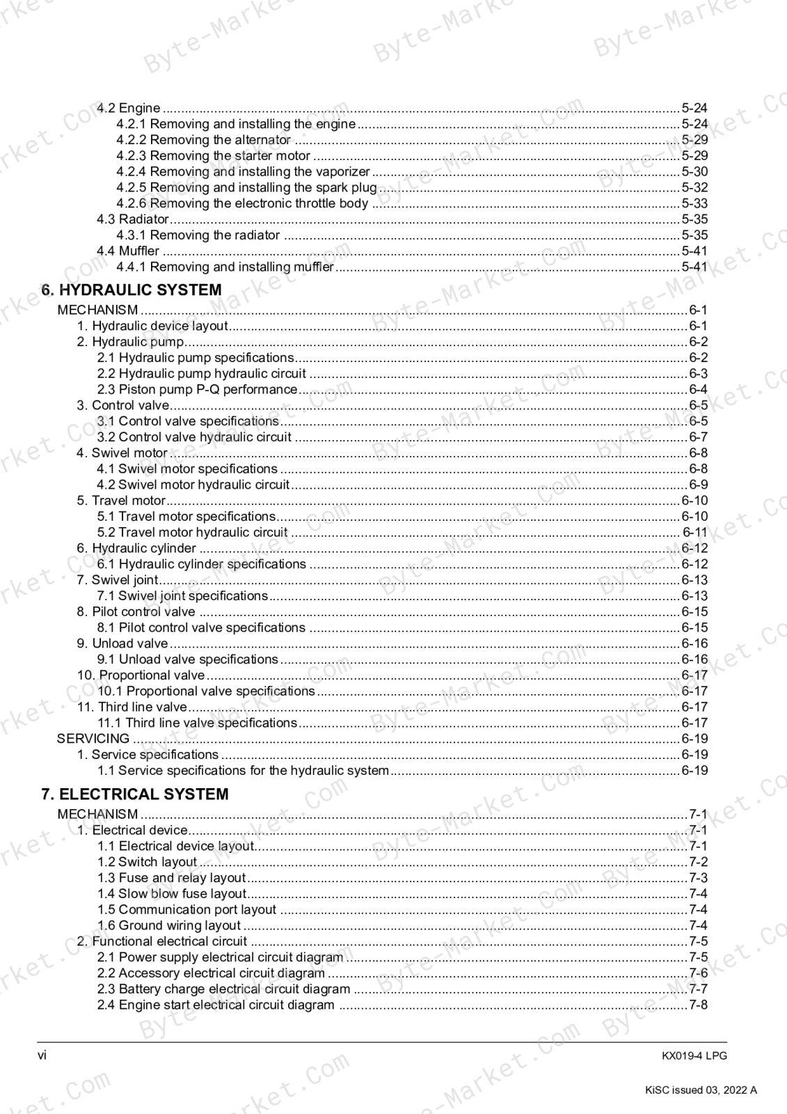
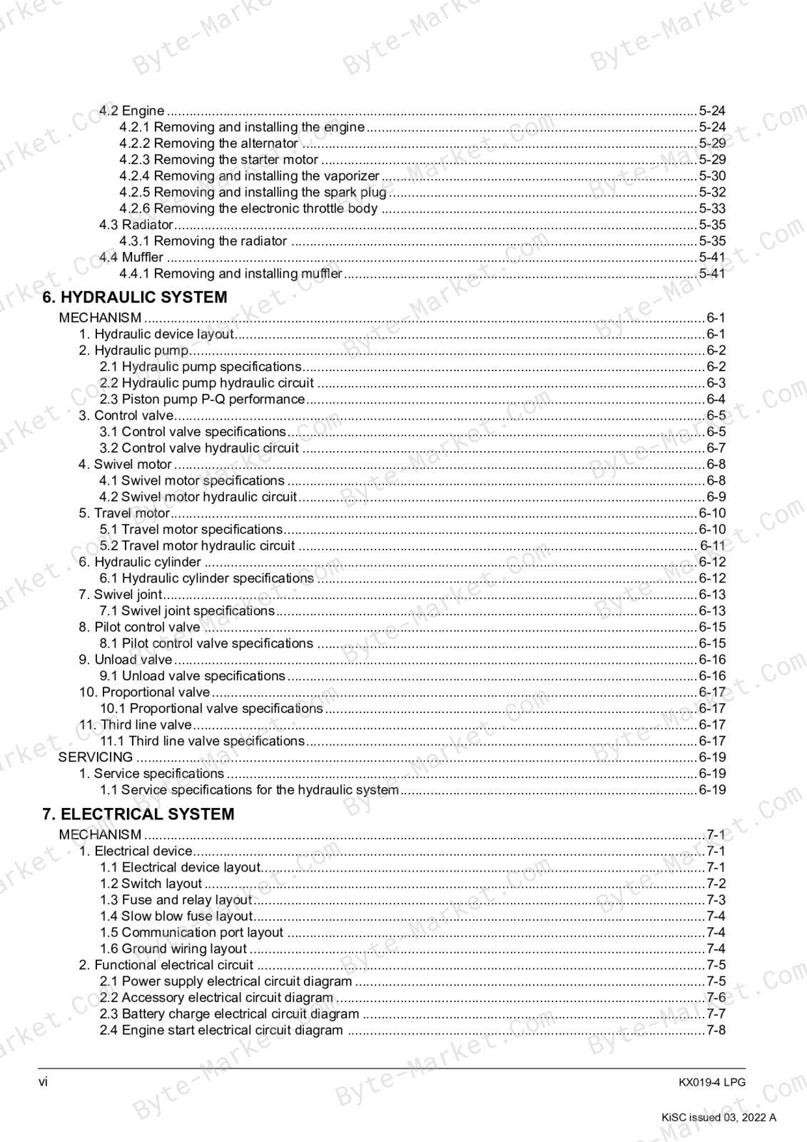
- Engine (5-24)
- Removing and installing the engine (5-24)
- Removing the alternator (5-29)
- Removing the starter motor (5-29)
- Removing and installing the vaporizer (5-30)
- Removing and installing the spark plug (5-32)
- Removing the electronic throttle body (5-33)
- Radiator (5-35)
- Removing the radiator (5-35)
- Muffler (5-41)
- Removing and installing muffler (5-41)
6. HYDRAULIC SYSTEM
- MECHANISM (6-1)
- Hydraulic pump specifications (6-2)
- Hydraulic pump hydraulic circuit (6-3)
- Piston pump P-Q performance (6-4)
- Control valve specifications (6-5)
- Control valve hydraulic circuit (6-7)
- Swivel motor specifications (6-8)
- Swivel motor hydraulic circuit (6-9)
- Travel motor specifications (6-10)
- Travel motor hydraulic circuit (6-11)
- Hydraulic cylinder specifications (6-12)
- Swivel joint specifications (6-13)
- Pilot control valve specifications (6-13)
- Pilot control valve specifications (6-15)
- Unload valve specifications (6-16)
- Proportional valve specifications (6-17)
- Third line valve specifications (6-17)
- SERVICING (6-19)
- Service specifications for the hydraulic system (6-19)
7. ELECTRICAL SYSTEM
- MECHANISM (7-1)
- Electrical device layout (7-1)
- Switch layout (7-2)
- Fuse and relay layout (7-1)
- Fuse and relay layout (7-3)
- Slow blow fuse layout (7-4)
- Communication port layout (7-4)
- Ground wiring layout (7-4)
- Power supply electrical circuit diagram (7-5)
- Accessory electrical circuit diagram (7-6)
- Battery charge electrical circuit diagram (7-7)
- Engine start electrical circuit diagram (7-8)
- Lever lock electrical circuit diagram (7-9)
- AUX operation electrical circuit diagram (7-11)
- Work light electrical circuit diagram (7-13)
- Fuel reserve tank electrical circuit diagram (7-14)
- Meter panel function (7-15)
- Display mode (7-15)
- Operating normal mode (7-16)
- Operating user setting mode (7-16)
- Service dealer mode (7-17)
- Service dealer mode list (7-17)
- Operating service dealer mode (7-19)
- Operating SET-1 (Tester mode) (7-19)
- Operating SET-2 (Reading error history) (7-20)
- Operating SET-3 (Clearing error history) (7-20)
- Operating SET-4 (Dealer settings) (7-20)
- Operating SET-5 (Reading all error history) (7-20)
- Operating SET-5 (Reading all error history) (7-21)
- SERVICING (7-23)
- Error warning list (Red lamp) (7-23)
- Engine system error (Red lamp) (7-24)
- Lamp warning list (7-26)
- Handling E:053CAN communication error (Engine) (7-27)
8. APPENDICES
- APPENDICES (8-1)
- Service specifications for the machine body (8-1)
- Service specifications for the engine (8-3)
- Service specifications for the hydraulic system (8-3)
- Piston pump P-Q performance (8-6)
- AUX P-Q performance (8-7)
- Service dealer mode (8-6)
- Service dealer mode (8-9)
- Tester mode (8-9)
- Default settings (8-10)
- ABBREVIATIONS
- KX019-4 LPG
- DANGER
- 1-2 KX019-4 LPG
- KX019-4 LPG
- 1-4 KX019-4 LPG
- KX019-4 LPG
- 1-6 KX019-4 LPG
- KX019-4 LPG
- 1-8 KX019-4 LPG
- KX019-4 LPG
- 1-10 KX019-4 LPG
- KX019-4 LPG
- 1-12 KX019-4 LPG
- KX019-4 LPG
- 1-14 KX019-4 LPG
- Locking the controls
- Locking the control lever
- Engine emergency stop
- Protective structure canopy
- Locking the controls
- KX019-4 LPG
- Locking the swivel frame
- 1-16 KX019-4 LPG
- • A
- DGUV79:
- KX019-4 LPG
- GENERAL WORKING INSTRUCTIONS
- – T
- KX019-4 LPG
- 2-2 KX019-4 LPG
- in.) without making any gaps
- in.)
- to 5.0 mm (0.12 to
- in.)
- KX019-4 LPG
- 2-4 KX019-4 LPG
- CAUTION
- KX019-4 LPG
- 2-6 KX019-4 LPG
- KX019-4 LPG
- IMPORTANT
- 2-8 KX019-4 LPG
- KX019-4 LPG
- 2-10 KX019-4 LPG
Note: The full manual contains approximately 238 pages of detailed diagnostic procedures, DTC tables, wiring diagrams, and connector pinouts that extend well beyond the Contents listing above. The manual includes 0 DTC entries with detailed inspection steps for each fault code, plus active test routines, data monitor signals, and checking-by-system procedures.


No questions found.