
Kubota Workshop Manual
Kubota KX91-3 and KX101-3 Workshop Manual
Document number 97899-60520 · English PDF edition · 610 pages
About this manual
Kubota published this Workshop Manual for the KX91-3 and KX101-3 excavator models. It brings the documented service and technical-reference material for those named excavators into a single publication.
The manual is especially useful for work that crosses electrical and hydraulic systems: it includes electrical troubleshooting, alongside hydraulic diagrams, pressure-test evidence, and valve-adjustment information.
Use the Manual Contents below to check that the exact repair, inspection, or maintenance procedure you need is included in this publication.
Manual details
- Manufacturer
- Kubota
- Manual type
- Workshop Manual
- Models
- KX91-3 and KX101-3
- Document number
- 97899-60520
- Publication year
- 2011
- Language
- English
- Page count
- 610
Product highlights
Electrical systems
The manual includes wiring diagrams and electrical troubleshooting.
Hydraulic systems
The manual includes hydraulic circuit diagrams, hydraulic pressure-test material, and hydraulic valve-adjustment material.
Diagnostics
The manual includes diagnostic service-mode information and sensor-testing information.
Specifications and settings
The manual includes reference information for torque specifications, wear limits, and dimensions.
Special tools
A special-tools section is included.
Maintenance
The manual includes a maintenance schedule.
Manual contents
Use these source headings to locate the task or system you need in the PDF.
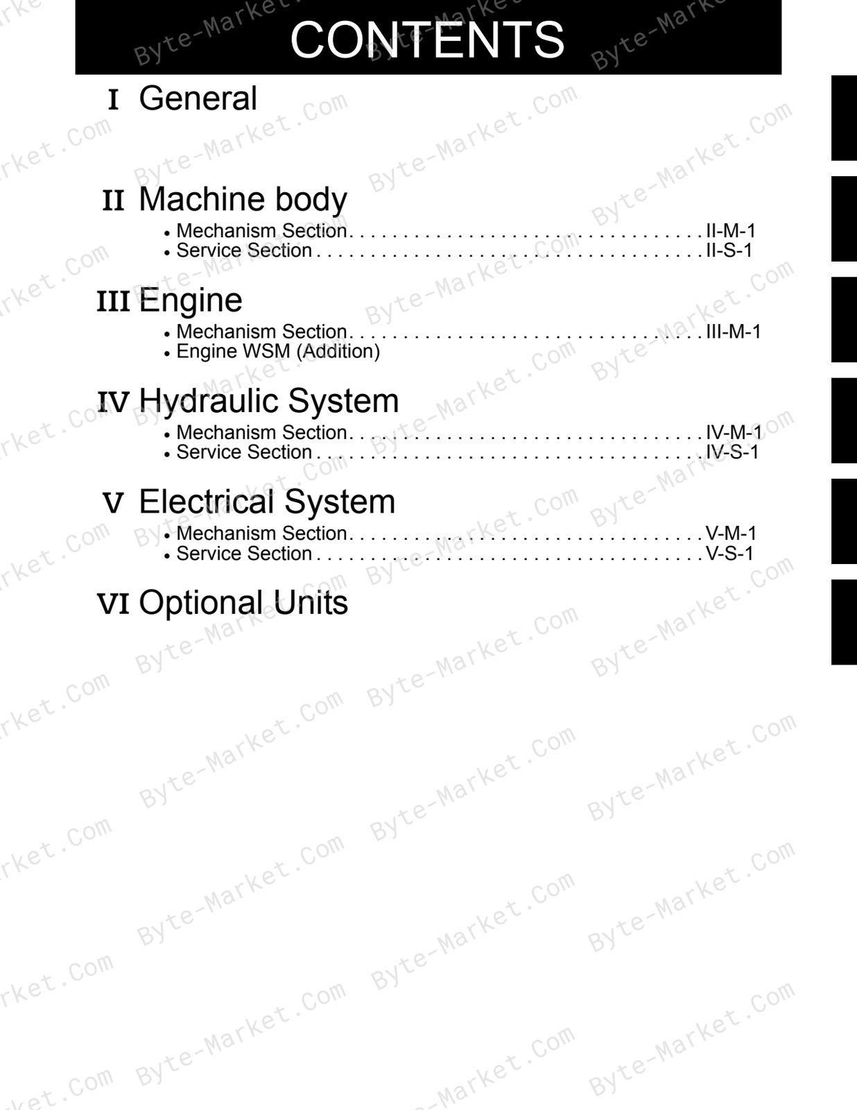
- CONTENTS — p. 2
- I. General — p. 4
- A. Body and engine identification marks — p. 6
- B. Safty precautions for servicing, disassembly and reassembly — p. 7
- a. Safty measures before starting work — p. 7
- (1) Work clothes — p. 7
- (2) Inspecting equipment and tools — p. 7
- (3) Keep workshop in order — p. 7
- b. Safty measures during work — p. 7
- (1) Protectors — p. 7
- (2) Team work — p. 7
- (3) Disassembly and assembly — p. 7
- (4) Cranes — p. 7
- (5) Others — p. 7
- c. Preparation for disassembly — p. 8
- (1) Cleaning — p. 8
- (2) Acceptance inspection — p. 8
- (3) Equipment and tools — p. 8
- d. Precautions for disassembly and reassembly — p. 8
- (1) Disassembly — p. 8
- (2) Reassembly — p. 8
- a. Safty measures before starting work — p. 7
- C. IMPORTANT SAFTY PROCESS AND CRITICAL FUNCTIONAL PROCESS — p. 9
- a. Essential Adhesives — p. 9
- b. Important Safety Process . — p. 9
- c. Important Critical Functional Process . — p. 9
- D. IMPORTANT INSPECTION ITEMS AFTER REASSEMBLING — p. 9
- a Operate the Machine and check for Unusual Noise and Vibrations. — p. 9
- b Make Sure the Safety decals and Wireharness Clamps are in their Specified Positions. — p. 9
- c With the Machine Front in a Specified Posture, Check the Amount of Hydrauric Oil — p. 9
- E. SERVICING FUNDAMENTALS — p. 10
- a. Items for Servicing — p. 10
- b. O-ring, Oil seal, Circlip and Roll Pin — p. 12
- c. Piping — p. 14
- (1) General precautions — p. 14
- (2) Hydraulic hose — p. 14
- (3) Precautions in tightening the bolts and nuts — p. 14
- (4) Hose screw — p. 15
- Metric Size Hose — p. 15
- (5) Joint bodies — p. 15
- (6) Tightening torque table for hose clamp (Screw type) — p. 16
- (7) Nuts for piping — p. 16
- (8) Tightening torque of bolts and nuts — p. 17
- (9) Types and materials of bolts and nuts — p. 17
- II. Machine body(Mechanism section) — p. 18
- A. Front attachment — p. 20
- a. Greasing points — p. 20
- b. Bucket interchangeability — p. 21
- B. Swivel frame and components — p. 22
- a. Accel lever (Standard-version) — p. 23
- (1) Engine RPM — p. 23
- (2)Accel lever operating force — p. 23
- b. Auto idle-version — p. 24
- (1) Accel lever side — p. 24
- (2) AI motor side — p. 25
- (3) Engine side — p. 25
- c. Accel cable — p. 26
- d. Swivel bearing — p. 27
- a. Accel lever (Standard-version) — p. 23
- C. Track frame and components — p. 28
- a. Tension spring pre-set length — p. 28
- b. Additional parts to change from rubber track to iron track — p. 28
- c. Track tension adjustment — p. 29
- d. Grease tension cylinder, L — p. 30
- e. Drive sprocket — p. 31
- f. Rubber track — p. 32
- g. Iron track — p. 33
- A. Front attachment — p. 20
- II. Machine body(Service section) — p. 34
- A. Specifications — p. 36
- a. Machine Weight — p. 36
- (1) KE, KDG, KUK version — p. 36
- (2) KTC, KCL, KTA version — p. 36
- b. Machine specifications — p. 37
- (1) KE, KDG, KUK version — p. 37
- (2) KTC, KCL, KTA version — p. 38
- c. Lever stroke and operating force — p. 39
- d. Dimensions of Parts — p. 40
- (1) Front pins — p. 40
- (2) Bucket — p. 41
- (3) Rubber crawler — p. 44
- (4) Iron crawler — p. 44
- (5) Track toller, idler, sprocket — p. 45
- (6) Dozer — p. 46
- (7) Parts weight — p. 47
- (8) Quantity Water and Oil — p. 49
- a. Machine Weight — p. 36
- B. Front attachment — p. 50
- a. Parts designation — p. 50
- b. Exchange of bucket (Kubota Japan Bucket) — p. 53
- c. Exchange of bucket teeth and side cutter — p. 54
- d. Installing direction of dust seal — p. 55
- e. Installation of thrust collar on the swing bracket — p. 55
- e-1. Service tip to ease customer complain — p. 56
- e-2. Swing bracket pin & bush. — p. 57
- e-3. Replacing the swing bracket support bush — p. 58
- e-4. Measuring the swing bracket looseness — p. 64
- f. Installing direction of fixing pin bolts — p. 66
- g. Front hoses and clamps — p. 67
- C. Upper Structure — p. 68
- a. Swivel bearing — p. 68
- b. Traveling lever — p. 69
- d. Traveling lever adjustment — p. 70
- e. Traveling lever lock — p. 71
- Adjusting the lever's neutral position — p. 71
- f. Accelarator lever — p. 72
- (1) KE, KUK, KDG version — p. 72
- (2) KTC, KU, KTA version — p. 72
- g. Dozer lever — p. 73
- h. Swing pedal — p. 74
- i. Auxiliary port pedal — p. 75
- j. Location of links for each operation — p. 76
- D. Under carriage — p. 78
- a. Track tension device — p. 78
- b. Crawler installation — p. 79
- c. Track Roller and Upper Roller installation — p. 80
- A. Specifications — p. 36
- III. Engine(Mechanism section) — p. 82
- A. Specification & features — p. 84
- a. Specifications — p. 84
- b. Features — p. 84
- B. Fuel injection pump — p. 85
- a. Structure — p. 85
- b. Precaution of removing reassembly — p. 86
- (1) Removing injection pump — p. 86
- (2) Mounting of injection pump — p. 86
- (3) Engine stop lever installation — p. 87
- C. Radiator fan & coupling flange — p. 90
- a. Fan belt tension adjustment — p. 90
- b. Alternator mounting bolt torque: — p. 90
- c. Temp. sensor tightning torque: — p. 90
- d. Fan flange bolt tightning torque: — p. 90
- e. Bolt tightning torque of coupling flange — p. 90
- f. Coupling flange — p. 91
- D. Other parts — p. 91
- a. Fuel filter — p. 91
- b. Air filter — p. 92
- c. Thermostat — p. 93
- E. Technical Data — p. 94
- Engine Specifications — p. 94
- F. Performance Curve — p. 95
- A. Specification & features — p. 84
- III. Engine(Engine WSM (Addition)) — p. 98
- IV. Hydraulic system(Mechanism section) — p. 210
- A. Features of hydraulic system — p. 212
- B. Hydraulic system specifications — p. 213
- C. Main pump — p. 214
- a. Structure & specifications — p. 214
- b. Performance curve — p. 215
- Variable displacement pump — p. 215
- Variable displacement pump — p. 216
- D. Control valve — p. 217
- a. Specifications — p. 217
- b. General view of control valve — p. 218
- c. Control valve circuit diagram — p. 220
- d. Control valve sectional view — p. 221
- e. Arm regeneration circuit — p. 227
- (1) Arm dump — p. 227
- (2) Arm Crowd — p. 227
- f. Oil flow of lock valve — p. 228
- (1) Operation of lock valve — p. 228
- (2) Boom operation — p. 230
- g. Function of lock valve (Anti-drift valve) — p. 232
- (1) Boom cylinder holding function — p. 232
- (2) Boom up function — p. 232
- (3) Boom-down function — p. 232
- h. Relief valve/Anti-cavitation valve — p. 233
- i. Straight travel circuit — p. 234
- j. Other functions — p. 235
- (1) Interval oil flow — p. 235
- E. Pilot valve — p. 236
- a. Structure & specifications — p. 236
- b. Pilot valve control diagram — p. 238
- F. Swivel motor — p. 239
- a. Structure & specifications — p. 239
- b. Function of negative brake — p. 242
- (1) Negative brake function(Unload condition) — p. 242
- (2) Negative brake release(On-load condition) — p. 242
- c. Function of valve section — p. 243
- (1)Make-up valve — p. 243
- (2)Function of shockless valve — p. 243
- (4) Relief valve — p. 244
- (5) Shockless piston — p. 244
- (6) Make-up poppet — p. 244
- G. Rotary joint (Swivel joint) — p. 245
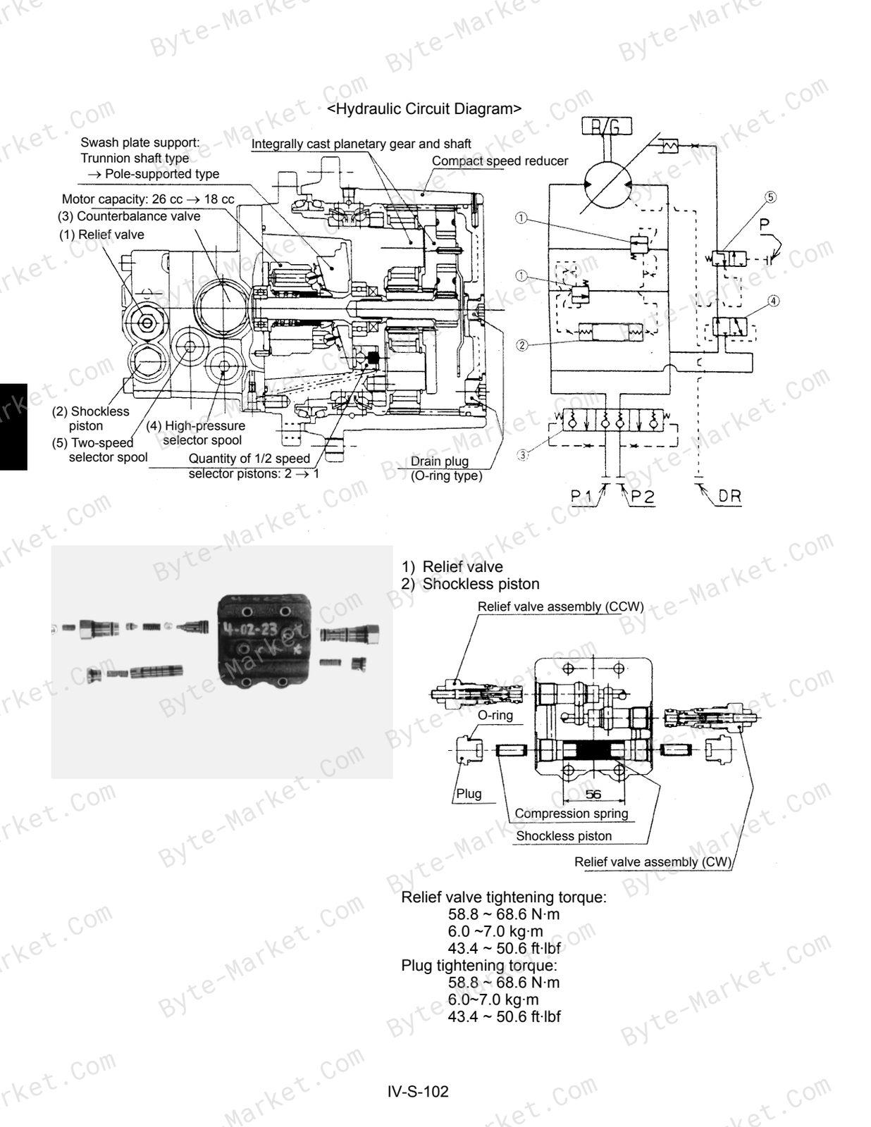
- H. Travel motor — p. 246
- a. Structure & specifications : KTC, KCL, KTA version — p. 246
- (1) Relief valve — p. 246
- (2) Shockless piston — p. 246
- (3) Counter balance valve — p. 247
- (4) High pressure selection spool — p. 247
- (5)Hi-Lo change spool — p. 247
- b. Operation of piston motor — p. 248
- c. Function of shockless valve — p. 249
- a. Structure & specifications : KTC, KCL, KTA version — p. 246
- I. Other components — p. 251
- a. Change valve with accumulator : EU version — p. 251
- (1) Pressure relief valve: a4 — p. 252
- (2) Pressure relief valve: a5 — p. 253
- (3) Electro-magnetically directional spool valves — p. 254
- b. Pilot filter — p. 255
- c. Return filter — p. 256
- d. Suction strainer — p. 256
- a. Change valve with accumulator : EU version — p. 251
- J. Hydraulic circuit diagram — p. 258
- a. KX91-3 European - version — p. 258
- b. KX101-3 European - version — p. 260
- c. KX91-3 KTC, KCL - version — p. 262
- d. KX91-3 KTA - version — p. 263
- d. Hydraulic components layout — p. 264
- a. Actual service port flow:KX91-3 KTA-version only — p. 266
- d. Installing direction of dust seal — p. 268
- e. Installation of thrust collar on the swing bracket — p. 268
- IV. Hydraulic system(Service section) — p. 270
- A. Troubleshooting — p. 272
- a. Common Circuit — p. 272
- b. Front Attachment — p. 274
- c. Swivel Circuit — p. 277
- d. Travel Circuit — p. 279
- B. Specifications — p. 280
- a. Relief valve pressure setting — p. 280
- b. Pump — p. 282
- (1) KE, KDG, KUK version — p. 282
- (2) KTC, KCL, KTA version — p. 283
- c. Cylinder — p. 284
- (1) Cylinder operating speed — p. 284
- (2) Cylinder natural fall amount — p. 284
- (3) Cylinder specifications — p. 285
- d. Swivel Performance — p. 288
- (1) KE, KDG, KUK version — p. 288
- e. Traveling Performance — p. 289
- (1) KE, KDG, KUK version — p. 289
- (2) KTC, KCL, KTA version — p. 290
- C. Testing — p. 291
- a. Testing Instruments & special tools — p. 291
- b. Pump flow — p. 293
- c. Pilot pressure — p. 294
- (1) Primary pressure — p. 294
- (2) Secondary pressure — p. 295
- d. Main relief valve — p. 296
- e. Overload relief valve — p. 298
- f. Swivel brake valve pressure — p. 300
- g. Traveling motor drain amount — p. 302
- h. Swivel motor drain amount — p. 303
- i. Swivel motor block performance — p. 304
- j. Traveling motor block performance — p. 305
- k. Operating speed — p. 306
- (1) Checking each operating speed. — p. 306
- (2) Boom cylinder — p. 306
- (3) Arm cylinder — p. 306
- (4) Bucket cylinder — p. 307
- (5) Swing cylinder — p. 307
- (6) Dozer cylinder — p. 307
- (7) Swivel speed — p. 308
- (8) Traveling speed — p. 308
- l. Straight travel performance — p. 308
- m. Cylinder natural fall amount — p. 309
- n. Control and Traveling lever operating force — p. 309
- o. Lever stroke — p. 309
- p. Specification sheet : Drain amount, Swivel motor — p. 310
- q. Specification sheet : Drain amount, Wheel motor (Travel motor) — p. 311
- D. Disassembling and Assembling — p. 312
- a. Coupling flange — p. 312
- b. Pump — p. 313
- (1) Components of pump [KX91-3, KX101-3] — p. 313
- (2) Adaptor installation on the pump — p. 314
- (3) Disassembling and assembling — p. 315
- c. Control valve and relief valve — p. 339
- (1) General precautions for servicing control valve — p. 339
- (2) Components of the control valve — p. 341
- (3) Inner parts of the control valve — p. 342
- (4) Adaptor installation — p. 343
- (5) Disassembling of the control valve — p. 344
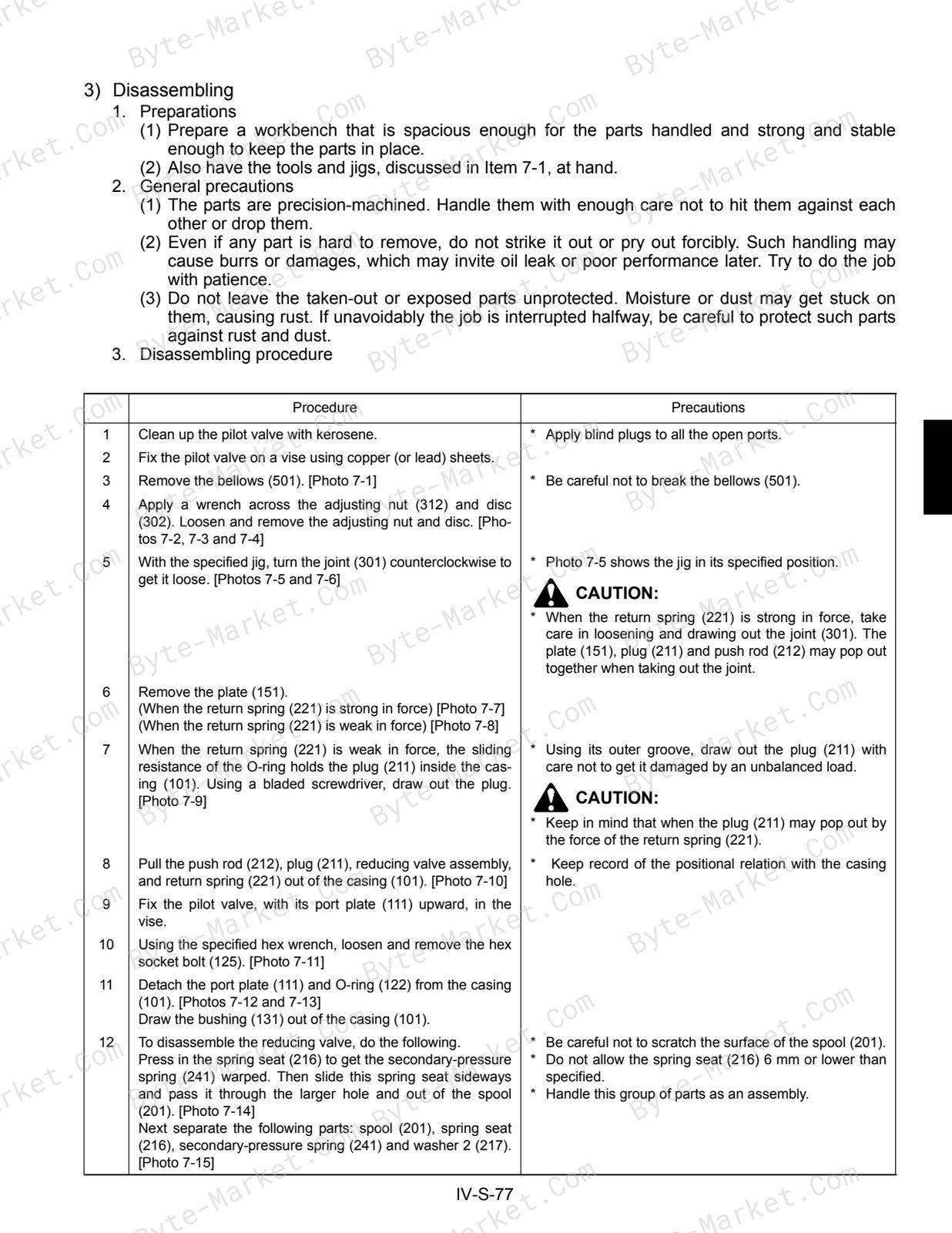
- d. Pilot valve — p. 345
- (1) Components of the pilot valve — p. 345
- (2) Adaptor and hose installation — p. 346
- (3) Disassembling and assembling (KTC, KCL, KTA version) — p. 347
- (4) Trouble shooting — p. 359
- e. Swivel motor (KTC, KCL, KTA version) — p. 360
- (1) Components of the swivel motor — p. 360
- (2) Inner parts of the swivel motor — p. 363
- (3) Assembling of the swivel motor (KTC, KCL, KTA version) — p. 366
- f. Traveling motor — p. 371
- (1) Components of the traveling motor (KTC, KCL, KTA version) — p. 371
- (2) Inner parts of the traveling motor — p. 375
- (3) Assembling of the traveling motor (KTC, KCL, KTA version) — p. 379
- g. Rotary joint — p. 390
- (1) Inner parts of the rotary joint — p. 390
- (2) Assembling of the rotary joint — p. 391
- (3) Adaptor installation on the rotary joint (KTC, KCL, KTA version) — p. 392
- h. Cylinder (KE, KDG, KUK version) — p. 393
- (1) Inner parts of the cylinder — p. 393
- (2) Tightening torque — p. 398
- (3) Disassembling and assembling — p. 400
- h. Cylinder (KTC, KCL, KTA version) — p. 405
- (1) Inner parts of the cylinder — p. 405
- (2) Tightening torque — p. 410
- (3) Disassembling and assembling — p. 412
- (4) Inspection — p. 415
- i. Other hydraulic device — p. 416
- (1)Change value — p. 416
- (2) TPSS valve (KTC, KCL, KTA version only) — p. 418
- j. Hose — p. 419
- (1) Pilot hose — p. 419
- (2) Delivery hose — p. 422
- (3) Hose connection around Rotary Joint (KTC, KCL, KTA version) — p. 425
- (4) Hose connection on control valve (KTC, KCL, KTA version) — p. 426
- (5) Return circuite (KTC, KCL, KTA version) — p. 428
- (6) Drain circuit (KTC, KCL, KTA version) — p. 429
- (7) Traveling motor and dozer — p. 430
- A. Troubleshooting — p. 272
- V. Electrical system(Mechanism section) — p. 432
- A. Outline — p. 434
- B. Components & harness layout — p. 436
- C. Couplers, KX91-3, 101-3 Standard version — p. 437
- D. Function of main circuit — p. 438
- a. Battery circuit (Standard-version) — p. 438
- b. Safty Relay circuit (Automatic release function) Standard-version — p. 439
- (1) Operation — p. 439
- (2) Function chart of auto release controller — p. 440
- c. Auto glow circuit (Standard-version) — p. 441
- (1) Function — p. 441
- d. Fuel control circuit (STD, AI-version) — p. 443
- (1) Function — p. 443
- (2) Engine stop solenoid (STD, AI-version) — p. 444
- e. Engine oil pressure sensor circuit (STD, AI-version) — p. 445
- Oil switch — p. 445
- f. Horn circuit (STD, AI-version) — p. 446
- (1) Structure — p. 446
- (2) Function — p. 446
- (3) Current flow — p. 447
- (4) Horn circuit — p. 448
- g. Cab & Working lamp circuit (STD, AI-version) — p. 449
- h. Meter panel (Standard-version) — p. 450
- i. Heater circuit (STD, AI-version) — p. 451
- j. Travel hi-speed control circuit (STD, AI-version) — p. 452
- k. Auto idle control system (AI-version) — p. 453
- (1)Purpose — p. 453
- (2)Auto idle function mechanism — p. 453
- (3) AI function layout — p. 454
- (4) Behavior when the control lever is returned to neutral — p. 455
- (5) Behavior when the control lever is operated: — p. 456
- (6) AI motor normal-turn circuit — p. 457
- (7) AI motor reverse-turn circuit — p. 458
- l. Battery direct line (AI-version) — p. 459
- m. Starter lock relay & auto release relay (AI-version) — p. 460
- (1) Safety start system — p. 460
- (2) Auto release function (AI- version) — p. 461
- n. Self holding relay circuit (AI-version) — p. 462
- o. Water temp. sensor circuit (AI-version) — p. 463
- p. Meter panel (AI-version) — p. 464
- q. AI controller unit (AI-version) — p. 465
- E. Structure and function of main components — p. 466
- a. Key switch (Engine starter switch) — p. 466
- b. Water temp. sensor — p. 466
- c. Safty lever lock switch, travel hi-low pedal switch — p. 467
- d. Relay — p. 468
- e. Engine speed sensor — p. 469
- f. Accel sensor, governor sensor — p. 470
- g. AI pressure switch — p. 471
- h. Foundamentals — p. 472
- F. Circuit diagram — p. 478
- a. Electric Circuit Diagram: KX91-3, 101-3 (Standard-version) — p. 478
- b. Functional Electric Circuit Diagram: KX91-3, 101-3 (Standard-version) — p. 480
- c. Electric Circuit Diagram: KX101-3 (AI-version, EU) — p. 482
- d. Functional Electric Circuit Diagram: KX101-3 (AI-version, EU) — p. 484
- e. Cab Electrical Diagram — p. 486
- KX91-3, KTC, KCC, KTA-version — p. 486
- f. Harness couplers of KX101-3, AI-version — p. 488
- V. Electrical system(Service section) — p. 490
- A. Troubleshooting — p. 492
- a. General — p. 492
- (1) How to diagnose — p. 492
- (2) INSPECTION OF HARNESS CONNECTOR — p. 493
- (3) Inspection — p. 494
- (4) INSPECTION INSTRUMENTS — p. 494
- (5) CHECKING SWITCHED — p. 495
- (6) Checking fuses — p. 496
- (7) Solenoid test method — p. 497
- (8) Checking relays — p. 498
- (9) Checking cables and wires — p. 499
- (10) HANDLING ON-VEHICLE BATTERY — p. 499
- b. Front attachment — p. 500
- (1) Working lamp failure — p. 500
- (2) Safety lever lock circuit malfunction — p. 501
- c. Engine electrical system — p. 502
- (1) Engine oil pressure failure — p. 502
- (2) Water temp. sensor circuit malfunction — p. 504
- (3) Fuel sensor circuit — p. 506
- (4) Engine stop solenoid — p. 507
- (5) Charging system malfunction — p. 508
- (6) Auto glow controller — p. 510
- (7) Auto release controller — p. 511
- d. Auto idle system — p. 512
- (1) Troubleshooting outline — p. 28
- (2) AI pressure switch test method — p. 513
- (3) Accel & governer sensor test method — p. 515
- (4) AI motor test method — p. 517
- (5) Engine speed sensor — p. 518
- (6) Auto glow circuit — p. 520
- e. AI version: AI controller (built-in microcomputer) Cases of trouble diagnosis with circuit tester — p. 522
- (1) “Water temperature sensor” line in trouble — p. 522
- (2) Other circuitry layouts and their trouble diagnosis — p. 524
- f. Auto Idle(AI) version: Trouble diagnosis with lamp — p. 525
- (1) General — p. 525
- (2) Display and identification of errors in operating mode — p. 526
- (3) Entering the service mode — p. 527
- (4) Working on the 5 menus in the service mode — p. 528
- (5) Working on the 3 menus in the service mode — p. 529
- (6) Working on the AI motor drive menus in the service mode — p. 530
- (7) Entering the setup mode — p. 531
- (8) Lamp-identified fail symptoms, trouble spots and possible causes — p. 535
- a. General — p. 492
- A. Troubleshooting — p. 492
- VI. Optional Units — p. 538
- A. KTA-version — p. 540
- a. Actual service port flow : KX91-3 KTA-version only — p. 540
- 1. Test method ; Testing circuit — p. 540
- 2. Service port flow test sample. — p. 541
- 3. P-Q performance of pump 2. — p. 542
- 4. Actual service port flow : KX91-3 KTA-version — p. 544
- 5. Actual service port flow : U35-3 KTA-version — p. 545
- b. Breaker performance test sample : KTA-version only — p. 546
- 1. Test machine : — p. 546
- 2. Heat balance test condition — p. 546
- 3. Breaker operating result : Sample Data — p. 546
- 4. Service port flow for breaker operation, theoretical — p. 547
- 5. Breaker operation test procedure — p. 548
- 6. Test Data Sheet — p. 549
- 7. Krupp breaker information — p. 550
- 8. SERVICE PORT OIL FLOW (KTA Version) — p. 551
- a. Actual service port flow : KX91-3 KTA-version only — p. 540
- B. KTC-version, optional kit — p. 552
- a. Installation Manual for Canopy Kit — p. 552
- 1. Introduction — p. 552
- 2. Item list of canopy kit — p. 552
- 3. Installation instruction — p. 553
- b. Installation Manual for Canopy Kit — p. 556
- 1. Introduction — p. 556
- 2. Item list of canopy kit — p. 556
- 3. Installation instruction — p. 557
- c. Working Light Installation Manual — p. 560
- 1. Introduction — p. 560
- 2. Item list of light kit — p. 560
- d. Installation Manual for Cabin Kit — p. 566
- 1. Introduction — p. 566
- 2. Item list of cabin kit — p. 566
- 3. Installation instruction — p. 567
- e. Installation Manual for Cabin Kit — p. 574
- 1. Introduction — p. 574
- 2. Item list of canopy kit — p. 574
- 3. Installation instruction — p. 575
- f. Item List of Heat Insulator Kit — p. 582
- 1. Introduction — p. 582
- 2. Item list — p. 582
- 3. Overview — p. 582
- 4. Heat Insulator Installation Instructions — p. 583
- 5. Spark Arresting Muffler Installation Instructions — p. 583
- 6. KX3 Spark Arrester Muffler Maintenance at Every 250 Excavator Service Hours — p. 583
- g. Installation Manual Auxiliary Relief Valve and Cylinder Mounting Bracket Kit — p. 586
- 1. Introduction — p. 586
- 2. SAFE OPERATION BEFORE THUMB INSTALLATION — p. 586
- 3. WELDING INSTRUCTIONS — p. 586
- 4. Parts list — p. 587
- 5. Installation instructions — p. 587
- h. THIRD LINE KIT — p. 592
- 1. Introduction — p. 592
- 2. Preparation for installation — p. 592
- 3. Installation instruction — p. 593
- 4. Inspection after installation — p. 597
- i. STEEL CRAWLER KIT (Convert tracks from rubber to steel) INSTALLATION INSTRUCTION FOR MOUNTING STEEL TRACKS — p. 600
- 1. Removing rubber tracks — p. 600
- 2. Changing the tension of spring — p. 601
- 3. Mounting iron crawlers — p. 602
- 4. Adjustiment of crawlers (Steel tracks) — p. 602
- j. STEEL CRAWLER KIT (Convert tracks from rubber to steel) INSTALLATION INSTRUCTION FOR MOUNTING STEEL TRACKS — p. 604
- 1. Removing rubber tracks — p. 604
- 2. Changing the tension of spring — p. 605
- 3. Mounting iron crawlers — p. 606
- 4. Adjustiment of crawlers (Steel tracks) — p. 606
- a. Installation Manual for Canopy Kit — p. 552
- A. KTA-version — p. 540
Capabilities
The source outline indexes servicing instructions, disassembly and assembly, checking and adjustment, mechanism explanations, troubleshooting, and maintenance tasks. Use these source-backed headings to locate the applicable task or system in the source PDF, then confirm model-specific notes, specifications, illustrations, and operating conditions at the relevant page before carrying out service work.
Keep the source's safety sequence, prerequisite steps, labels, units, configuration notes, and footnotes with the selected task; do not apply an isolated value outside the conditions stated in the manual.
Technical reference
Reference tables include torque settings, wear limits, and dimensions for service checks, adjustment work, and specification lookup. Use the values and conditions in the PDF for the applicable model and procedure.
- Service limits and settings: torque settings and wear limits.
- Machine specifications: dimensions.
Delivery
This manual is supplied as a digital PDF file and is available for instant download after purchase. No physical media is shipped.
References
Kubota Workshop Manual for Excavator, document code 97899-60520, PDF edition.


No questions found.