
Kubota Workshop Manual
Kubota M4900, M5700, and M5700HD Workshop Manual
Document number 9Y011-12555 · English PDF edition · 563 pages
About this manual
Kubota published this Workshop Manual for the M4900, M5700, and M5700HD tractor models. It brings the documented service and technical-reference material for those named tractors into a single publication.
Its documented technical value includes torque settings and wear limits for service checks and specification lookup. Use the values and conditions stated in the PDF for the applicable model and procedure.
Use the Manual Contents below to check that the exact repair, inspection, or maintenance procedure you need is included in this publication.
Manual details
- Manufacturer
- Kubota
- Manual type
- Workshop Manual
- Models
- M4900, M5700, and M5700HD
- Document number
- 9Y011-12555
- Publication year
- 2000
- Language
- English
- Page count
- 563
Product highlights
Engine systems and service
The manual includes engine-system service and repair sections.
Clutch and driveline
The manual includes clutch, transmission, and driveline service sections.
Hydraulic and steering systems
The manual includes hydraulic and steering system sections.
Electrical systems
The manual includes electrical-system sections and circuit information.
Troubleshooting
The manual includes troubleshooting sections for documented systems.
Inspection, servicing, and adjustment
The manual includes inspection, servicing, and adjustment sections.
Disassembly and reassembly
The manual includes disassembly and reassembly procedures.
Specifications and settings
The manual includes specifications, settings, and torque-reference sections.
Manual contents
Use these source headings to locate the task or system you need in the PDF.
- [1] FEATURES — p. G-1
- [2] TRACTOR IDENTIFICATION — p. G-2
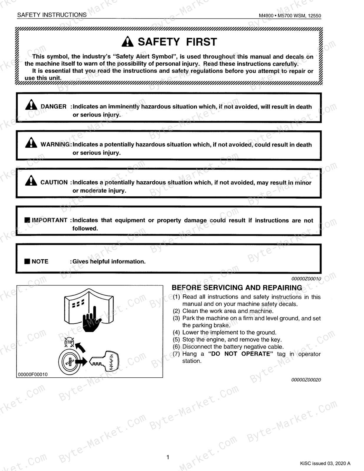
- [3] GENERAL PRECAUTIONS — p. G-3
- [4] HANDLING PRECAUTIONS FOR ELECTRICAL PARTS AND WIRING — p. G-4
- (1) Wiring — p. G-4
- (2) Battery — p. G-6
- (3) Fuse — p. G-6
- (4) Connector — p. G-6
- (5) Handling of Circuit Tester — p. G-8
- [5] LUBRICANTS, FUEL AND COOLANT — p. G-9
- [6] TIGHTENING TORQUES (GENERAL USE SCREWS, BOLTS AND NUTS) — p. G-10
- [7] MAINTENANCE — p. G-11
- [8] CHECK AND MAINTENANCE — p. G-12
- (1) Daily Check — p. G-12
- (2) Check Points of Initial 50 Hours — p. G-13
- (3) Check Points of Every 50 Hours — p. G-16
- (4) Check Points of Every 100 Hours — p. G-17
- (5) Check Points of Every 200 Hours — p. G-19
- (6) Check Points of Every 400 Hours — p. G-23
- (7) Check Points of Every 600 Hours — p. G-24
- (8) Check Points of Every 800 Hours — p. G-25
- (9) Check Points of Every 1500 HOurs — p. G-25
- (10) Check Points of Every 3000 HOurs — p. G-25
- (11) Check Points of Every 1 Year — p. G-26
- (12) Check Points of Every 2 Years — p. G-27
- (13) Others — p. G-29
- [9] SPECIAL TOOLS — p. G-33
- [10] TIRES — p. G-48
- (1) Type of Tire — p. G-48
- (2) Tread Adjustment — p. G-48
- (2)-1 Front Wheels [2WD] — p. G-48
- (2)-2 Front Wheels [4WD] — p. G-48
- (2)-3 Rear Wheels — p. G-49
- (4) Tire Pressure — p. G-50
- (5) Tire Liquid Injection — p. G-51
- [11] IMPLEMENT LIMITATIONS — p. G-54
- [1] FEATURES — p. 1-M1
- [2] ENGINE BODY — p. 1-M1
- (1) Cylinder Block — p. 1-M1
- (2) Cylinder Head — p. 1-M2
- (3) Crankshaft — p. 1-M3
- (4) Piston and Piston Rings — p. 1-M3
- (5) Connecting Rod — p. 1-M4
- (6) Camshaft — p. 1-M4
- (7) Fuel Camshaft — p. 1-M4
- (8) Rocker Arm — p. 1-M5
- (9) Intake and Exhaust Valve — p. 1-M5
- (10) Flywheel — p. 1-M5
- [3] LUBRICATING SYSTEM Q — p. 1-M6
- (1) Oil Pump — p. 1-M7
- (2) Oil Filter and Relief Valve — p. 1-M7
- (3) Engine Oil Pressure Switch — p. 1-M7
- [4] COOLING SYSTEM — p. 1-M8
- (1) Water PUMD — p. 1-M9
- (2) Thermostat — p. 1-M9
- (3) Radiator — p. 1-M10
- (4) Radiator Cap — p. 1-M10
- [5] FUEL SYSTEM — p. 1-M11
- (1) Fuel Lines — p. 1-M11
- (2) Fuel Injection Pump — p. 1-M11
- (3) Fuel Injection NOZZle 2.0 — p. 1-M13
- (4) Fuel Filter — p. 1-M14
- (5) Fuel Feed Pump — p. 1-M15
- (6) Governor — p. 1-M15
- TROUBLESHOOTING — p. 1-S1
- SERVICING SPECIFICATIONS — p. 1-S4
- TIGHTENING TORQUES — p. 1-S10
- CHECKING, DISASSEMBLING AND SERVICING — p. 1-S11
- [1] SEPARATING ENGINE FROM TRACTOR — p. 1-S11
- DISASSEMBLING AND ASSEMBLING — p. 1-S11
- (1) Draining Coolant, Engine Oil and Transmission Fluid — p. 1-S11
- (2) Separating Front Axle Frame as a Unit — p. 1-S12
- DISASSEMBLING AND ASSEMBLING — p. 1-S11
- [2] CYLINDER HEAD — p. 1-S17
- CHECKING AND ADJUSTING — p. 1-S17
- DISASSEMBLING AND ASSEMBLING — p. 1-S19
- SERVICING — p. 1-S23
- [3] TIMING GEARS — p. 1-S28
- DISASSEMBLING AND ASSEMBLING — p. 1-S28
- SERVICING — p. 1-S33
- [4] CRANKCASE — p. 1-S36
- DISASSEMBLING AND ASSEMBLING — p. 1-S36
- SERVICING — p. 1-S41
- [5] LUBRICATING SYSTEM — p. 1-S50
- CHECKING AND ADJUSTING — p. 1-S50
- DISASSEMBLING AND ASSEMBLING — p. 1-S50
- SERVICING — p. 1-S50
- [6] COOLING SYSTEM — p. 1-S51
- CHECKING AND ADJUSTING — p. 1-S51
- DISASSEMBLING AND ASSEMBLING — p. 1-S52
- SERVICING — p. 1-S53
- [7] FUEL SYSTEM — p. 1-S54
- CHECKING AND ADJUSTING — p. 1-S54
- (1) Injection Pump — p. 1-S54
- (2) Injection Nozzle — p. 1-S55
- DISASSEMBLING AND ASSEMBLING — p. 1-S57
- (1) Injection Nozzle — p. 1-S57
- CHECKING AND ADJUSTING — p. 1-S54
- [1] TRAVELLING CLUTCH Qu. ccs — p. 2-M1
- (1) Features — p. 2-M1
- (2) Travelling Clutch Linkage — p. 2-M1
- (3) Operation — p. 2-M2
- [2] PTO CLUTCH — p. 2-M4
- (1) Structure — p. 2-M4
- (2) Oil FIOW — p. 2-M4
- (3) PTO Clutch Valve — p. 2-M5
- (4) Shift Linkage oo. ce — p. 2-M7
- TROUBLESHOOTING — p. 2-S1
- SERVICING SPECIFICATIONS — p. 2-S3
- TIGHTENING TORQUES — p. 2-S4
- CHECKING, DISASSEMBLING AND SERVICING — p. 2-S5
- [1] TRAVELLING CLUTCH — p. 2-S5
- CHECKING AND ADJUSTING — p. 2-S5
- DISASSEMBLING AND ASSEMBLING — p. 2-S5
- (1) Removing Clutch Pedal and Shaft — p. 2-S5
- (2) Draining Transmission Fluid — p. 2-S7
- (3) Separating Engine and Clutch Housing Case — p. 2-S8
- (2) Removing Clutch — p. 2-S11
- SERVICING — p. 2-S12
- [2] HYDRAULIC PTO CLUTCH — p. 2-S14
- [2]-1 PTO CLUTCH VALVE — p. 2-S14
- CHECKING AND ADJUSTING — p. 2-S14
- DISASSEMBLING AND ASSEMBLING — p. 2-S15
- [2]-2 PTO CLUTCH — p. 2-S16
- DISASSEMBLING AND ASSEMBLING — p. 2-S16
- (1) Draining Transmission Fluid — p. 2-S16
- (2) Separating Transmission Case — p. 2-S16
- (3) Removing PTO Clutch — p. 2-S19
- (4) Disassembling PTO Clutch Pack — p. 2-S20
- SERVICING — p. 2-S22
- DISASSEMBLING AND ASSEMBLING — p. 2-S16
- [1] STRUCTURE — p. 3-M1
- (1) Shuttle Shift Section (Forward-Reverse) — p. 3-M3
- (2) Main Gear Shift Section 00.0 — p. 3-M4
- (3) Hi-Lo, Creep Shift Section — p. 3-M5
- (4) Four Wheel Drive Section (4WD Only) — p. 3-M8
- [2] PTO SYSTEM — p. 3-M9
- [3] DIFFERENTIAL GEAR — p. 3-M10
- (1) Structure wo — p. 3-M10
- (2) Operation — p. 3-M10
- [1] FEATURES — p. 4-M1
- [2] FINAL REDUCTION SYSTEM — p. 4-M2
- TROUBLESHOOTING — p. 4-S1
- SERVICING SPECIFICATIONS — p. 4-S1
- TIGHTENING TORQUES — p. 4-S1
- CHECKING, DISASSEMBLING AND SERVICING — p. 4-S2
- DISASSEMBLING AND ASSEMBLING — p. 4-S2
- (1) Separating Rear Axle Case from Transmission Case — p. 4-S2
- (2) Disassembling Planetary Gear — p. 4-S4
- (3) Disassembling Rear Axle — p. 4-S5
- SERVICING — p. 4-S5
- DISASSEMBLING AND ASSEMBLING — p. 4-S2
- [1] FEATURES — p. 5-M1
- [2] OPERATION — p. 5-M2
- [1] STRUCTURE. uo. eee — p. 6-M1
- (1) 2 Wheel Drive Type — p. 6-M1
- (2) 4 Wheel Drive Type — p. 6-M2
- [2] FRONT WHEEL ALIGNMENT — p. 6-M2
- TROUBLESHOOTING — p. 6-S1
- SERVICING SPECIFICATIONS — p. 6-S1
- TIGHTENING TORQUES — p. 6-S4
- CHECKING, DISASSEMBLING AND SERVICING — p. 6-S5
- CHECKING AND ADJUSTING — p. 6-S5
- DISASSEMBLING AND ASSEMBLING — p. 6-S7
- (1)-1 Separating Front Axle (2WD Type) — p. 6-S7
- (1)-2 Separating Front Axle (4WD Type) — p. 6-S7
- (2)-1 Disassembling Front Axle (2WD Type) — p. 6-S9
- (2)-2 Disassembling Front Axle (4WD Type) — p. 6-S11
- SERVICING — p. 6-S15
- (1) 2WD Type — p. 6-S15
- (2) 4WD Type — p. 6-S16
- [1] STEERING LINKAGE — p. 7-M1
- [2] POWER STEERING HYDRAULIC CIRCUIT — p. 7-M2
- [3] POWER STEERING SYSTEM HYDRAULIC PUMP — p. 7-M3
- [4] STEERING CONTROLLER — p. 7-M4
- (1) Control Valve — p. 7-M4
- (2) Metering Device (Gerotor) — p. 7-M5
- (3) Oil Flow — p. 7-M6
- [5] STEERING CYLINDER — p. 7-M9
- [1] THREE POINT HYDRAULIC SYSTEM — p. 8-M1
- [2] HYDRAULIC CIRCUIT FOR THREE POINT HYDRAULIC SYSTEM — p. 8-M2
- [3] HYDRAULIC PUMP — p. 8-M3
- [4] OIL FILTER — p. 8-M4
- [5] POSITION CONTROL VALVE — p. 8-M4
- [6] RELIEF VALVE — p. 8-M6
- [7] HYDRAULIC CYLINDER — p. 8-M7
- [8] LINKAGE MECHANISM — p. 8-M8
- (1) Position Control — p. 8-M8
- (2) Draft Control — p. 8-M10
- (3) Mixed Control — p. 8-M13
- (4) Cylinder Safety Valve (Surge Relief Valve) — p. 8-M13
- [10] AUXILIARY CONTROL VALVE — p. 8-M14
- (1) Self Cancelling with Detent (Standard) — p. 8-M14
- (2) Floating Valve with Detent (If Equipped) — p. 8-M17
- [1] WIRING DIAGRAM 0.0. cece cece — p. 9-M2
- (1) ROPS Type — p. 9-M2
- (2) CABIN Type (for USA) — p. 9-M4
- (2)-1 Body Harness — p. 9-M4
- (2)-2 CABIN Harness — p. 9-M8
- (3) CABIN Type (for CANADA) — p. 9-M10
- (3)-1 Body Harness 0.0 — p. 9-M10
- (3) CABIN Harness — p. 9-M14
- [2] ELECTRICAL CIRCUIT — p. 9-M16
- (1) ROPS Type — p. 9-M16
- (1)-1 Starting Section — p. 9-M16
- (1)-2 Lighting — p. 9-M17
- (1)-3 Panel Section — p. 9-M18
- (2) CABIN Type — p. 9-M19
- (2)-1 Starting Section — p. 9-M19
- (2)-2 Lighting Section 1 — p. 9-M20
- (2)-3 Lighting Section 2 — p. 9-M21
- (2)-4 Pnel Section — p. 9-M22
- (2)-5 Air Condition Section — p. 9-M23
- (2)-6 Accessory Section — p. 9-M24
- (2)-7 Deffogger Section — p. 9-M25
- (1) ROPS Type — p. 9-M16
- [3] STARTING SYSTEM — p. 9-M26
- (1) Starter Motor — p. 9-M28
- (1)-1 Roller Clutch — p. 9-M28
- (1)-2 Magnet SWitch oe — p. 9-M29
- (1)-3 Opetation of Starter Motor — p. 9-M29
- (2) Glow Control System — p. 9-M31
- (2)-1 Glow Plug — p. 9-M31
- (2)-2 Glow Relay — p. 9-M31
- (3) Safety Switch — p. 9-M32
- (1) Starter Motor — p. 9-M28
- [4] ENGINE KEY SWTCH SHUT-OFF SYSTEM — p. 9-M33
- (1) Engine Stop Solenoid — p. 9-M33
- [5] CHARGING SYSTEN — p. 9-M34
- (1) Alternator — p. 9-M34
- (2) IC Regulator — p. 9-M35
- (3) Operation of Charging System — p. 9-M36
- [6] LIGHTING SYSTEM — p. 9-M38
- [7] EASY CHECKER — p. 9-M39
- (1) Indication Items — p. 9-M40
- (2) PTO Clutch Lever Operation — p. 9-M40
- (3) Fuel Lacking — p. 9-M41
- (4) Engine Oil Pressure Alarm — p. 9-M41
- [8] GAUGES — p. 9-M42
- (1) Sensor — p. 9-M42
- (2) Gauge — p. 9-M43
- [1] AIR CONDITIONER SYSTEM — p. 10-M1
- (1) Principles of Air Conditioner — p. 10-M1
- (1)-1 Expansion and Evaporation — p. 10-M1
- (1)-2 How to — p. 10-M1
- (1)-3 Condensing Gaseous 00.0 — p. 10-M2
- (2) Outline of Aie Conditioning System — p. 10-M3
- (3) Refrigeration System — p. 10-M4
- (3)-1 Compressor — p. 10-M5
- (3)-2 CONCGENSES «0.0.2 — p. 10-M7
- (3)-3 Receiver — p. 10-M8
- (3)-4 Air Conditioner Unit — p. 10-M8
- (4) System Control — p. 10-M13
- (5) Electrical System — p. 10-M14
- (5)-1 Electrical Circuit — p. 10-M14
- (5)-2 Air Conditioner Main Relay and Compressor Relay — p. 10-M15
- (5)-3 Air Conditioner Blower Switch — p. 10-M16
- (5)-4 Pressure Switch — p. 10-M17
- (5)-5 Thermostat — p. 10-M20
- (1) Principles of Air Conditioner — p. 10-M1
- [2] WINDSHIELD WIPER — p. 10-M20
- (1) Front Windshield Wiper — p. 10-M20
- (2) Rear Windshield Wiper — p. 10-M21
- (3) Window Washe — p. 10-M22
- TROUBLESHOOTING-1 — p. 10-S1
- TROUBLESHOOTING-2 — p. 10-S3
- SERVICING SPECIFICATIONS — p. 10-S5
- PRECAUTIONS AT REPAIRING REFRIGERANT CYCLE — p. 10-S7
- HANDLING OF SERVICE TOOLS — p. 10-S8
- (1) Manifold Gauge Set — p. 10-S8
- (2) Refrigerant Charging Hose — p. 10-S10
- (3) Vacuum Pump Adaptor — p. 10-S11
- (4) Electric Gas Leak Tester — p. 10-S11
- (5) Can Tap Valve — p. 10-S11
- (6) T-joint — p. 10-S12
- (7) R134a Refrigerant Recovery and Recycling Machine — p. 10-S12
- HANDLING OF SERVICE TOOLS — p. 10-S8
- CHECKING AND CHARGING REFRIGERANT CYCLE — p. 10-S12
- [1] CHECKING WITH MANIFOLD GAUGE — p. 10-S12
- [2] DISCHARGING, EVACUATING AND CHARGING — p. 10-S17
- (1) Discharging the System — p. 10-S17
- (2) Evacuating the System — p. 10-S17
- (3) Charging the System — p. 10-S19
- (4) Checking Charge Refrigerant Amount — p. 10-S21
- CHECKING AND CHARGING REFRIGERANT CYCLE — p. 10-S22
- [1] SEPARATING CABIN FROM TRACTOR BODY — p. 10-S22
- DISASSEMBLING AND ASSEMBLING — p. 10-S22
- [2] COMPRESSOR — p. 10-S26
- CHECKING — p. 10-S26
- DISASSEMBLING AND ASSEMBLING — p. 10-S27
- [3] AIR CONDITIONING SYSTEM AND FRONT WINDSHIELD WIPER — p. 10-S28
- CHECKING — p. 10-S28
- (1) A/C Main Relay and Compressor Relay — p. 10-S28
- (2) Blower Switch — p. 10-S28
- (3) Blower Motor — p. 10-S29
- (4) Blower Resistor — p. 10-S30
- (5) A/C Switch — p. 10-S30
- (6) A/C Pressure Switch — p. 10-S31
- CHECKING — p. 10-S28
- [4] FRONT WINDSHIELD WIPER — p. 10-S32
- CHECKING — p. 10-S32
- (1) Front Wiper Switch — p. 10-S32
- DISASSEMBLING AND ASSEMBLING — p. 10-S33
- (1) Removing Air Conditioner Unit and Front Wiper Motor — p. 10-S33
- (2) Removing Air Conditioner Pipes — p. 10-S36
- (3) Removing Heater Hoses — p. 10-S38
- SERVICING — p. 10-S39
- (1) Air Conditioner Unit — p. 10-S39
- CHECKING — p. 10-S32
- [4] LIGHTING SYSTEM — p. 10-S40
- CHECKING — p. 10-S40
- (1) Working Light Switch — p. 10-S40
- CHECKING — p. 10-S40
- [5] OTHERS — p. 10-S40
- CHECKING — p. 10-S40
- (1) Rear Windshield Wiper Switch — p. 10-S40
- DISASSEMBLING AND ASSEMBLING — p. 10-S41
- (1) Cab Windshield — p. 10-S41
- CHECKING — p. 10-S40
Capabilities
The source outline indexes maintenance tasks, checking and adjustment, troubleshooting, servicing instructions, disassembly and assembly, and mechanism explanations. Use these source-backed headings to locate the applicable task or system in the source PDF, then confirm model-specific notes, specifications, illustrations, and operating conditions at the relevant page before carrying out service work.
Keep the source's safety sequence, prerequisite steps, labels, units, configuration notes, and footnotes with the selected task; do not apply an isolated value outside the conditions stated in the manual.
Technical reference
Reference tables include torque settings for service checks, adjustment work, and specification lookup. Use the values and conditions in the PDF for the applicable model and procedure.
- Service limits and settings: torque settings.
Delivery
This manual is supplied as a digital PDF file and is available for instant download after purchase. No physical media is shipped.
References
Kubota Workshop Manual for Tractor, document code 9Y011-12555, PDF edition.


No questions found.