
Kubota Workshop Manual
Kubota R420S, R520S, R420α, and R520α Workshop Manual
Document number 97899-60801 · English PDF edition · 352 pages
About this manual
Kubota published this Workshop Manual for the R420S, R520S, R420α, and R520α wheel loader models. It brings the documented service and technical-reference material for those named wheel loaders into a single publication.
Its documented technical value includes wear limits, dimensions, and emission data for service checks and specification lookup. Use the values and conditions stated in the PDF for the applicable model and procedure.
Use the Manual Contents below to check that the exact repair, inspection, or maintenance procedure you need is included in this publication.
Manual details
- Manufacturer
- Kubota
- Manual type
- Workshop Manual
- Models
- R420S, R520S, R420α, and R520α
- Document number
- 97899-60801
- Publication year
- 2003
- Language
- English
- Page count
- 352
Product highlights
Electrical systems
The manual includes electrical troubleshooting and pinouts.
Hydraulic systems
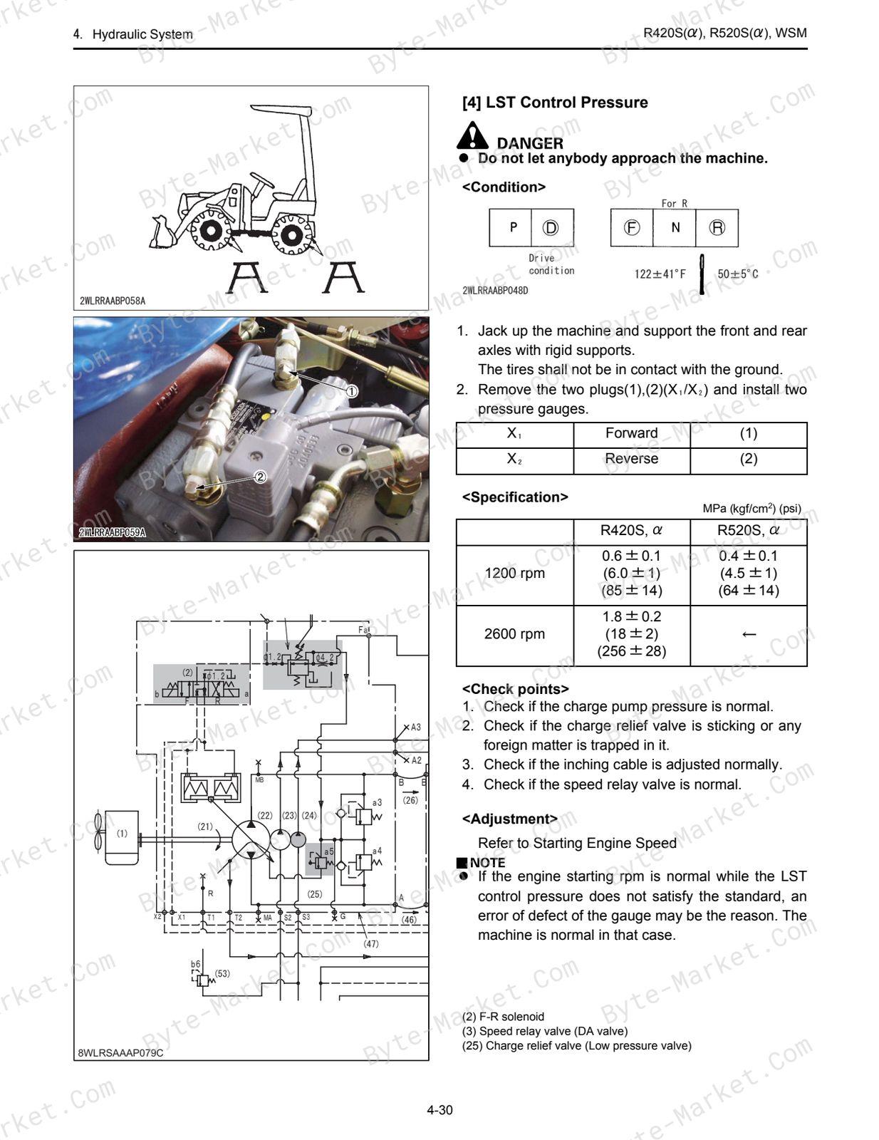
The manual includes hydraulic pressure-test material and hydraulic valve-adjustment material.
Specifications and settings
The manual includes reference information for wear limits and pressure specifications.
Special tools
A special-tools section is included.
Maintenance
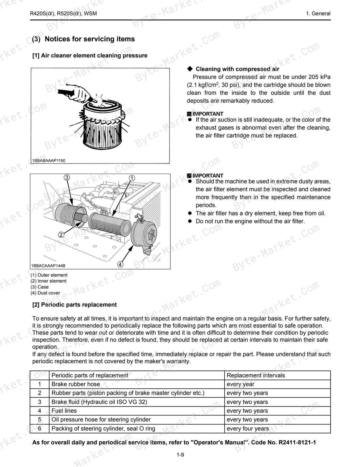
The manual includes a maintenance schedule.
Manual contents
Use these source headings to locate the task or system you need in the PDF.
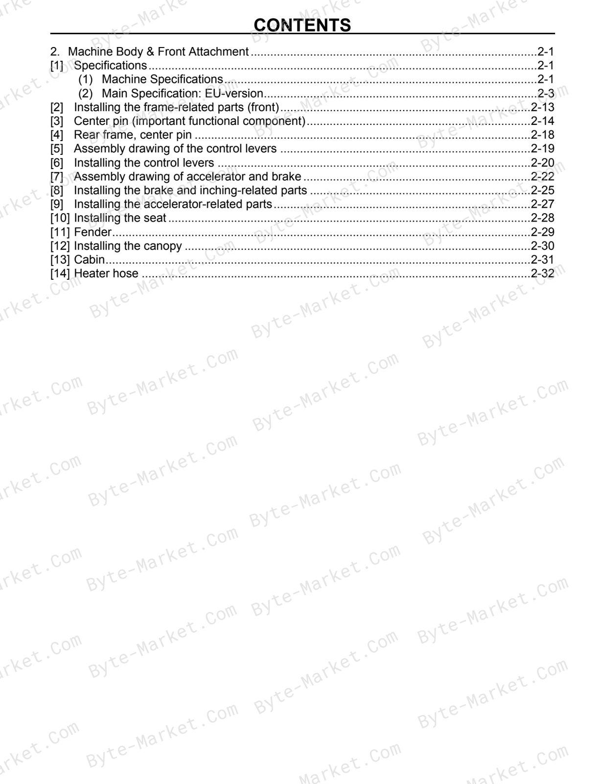
- 1. General — p. 3
- 2. Machine Body & Front Attachment — p. 3
- 3. Engine — p. 3
- 4. Hydraulic System — p. 3
- 5. Brake System and power train — p. 3
- 6. Electrical System — p. 3
- 1. General — p. 4
- (1) Safety measures before starting work — p. 6
- (2) Safety measures during work — p. 6
- (3) Preparation for disassembly — p. 7
- (4) Precautions for disassembly and reassembly — p. 7
- (1) Operate the machine and check for unusual noise and vibrations — p. 9
- (3) With the machine front in a specified posture, check the amount of hydraulic oil — p. 9
- (1) Service intervals — p. 10
- (2) Lubricants — p. 12
- (3) Notices for servicing items — p. 13
- (4) Tightening torque — p. 14
- 2. Machine Body & Front Attachment — p. 22
- (1) Machine Specifications — p. 23
- (2) Main Specification: EU-version — p. 25
- [10] Installing the seat — p. 50
- [11] Fender — p. 51
- [12] Installing the canopy — p. 52
- [13] Cabin — p. 53
- [14] Heater hose — p. 54
- 3. Engine — p. 55
- (1) Engine rubber mount — p. 62
- (2) Radiator, oil cooler — p. 64
- (3) Air cleaner — p. 65
- (4) Muffler — p. 67
- (5) Fuel hose route (S) — p. 68
- (6) Engine oil drain hose — p. 69
- (1) Outline — p. 70
- (2) Engine list for minor change — p. 71
- (4) Performance curve — p. 73
- (5) New engine structure — p. 78
- (6) Boost compensator and governor — p. 79
- (1) Specifications — p. 82
- (2) Structure — p. 83
- (3) Installation of turbo-charger — p. 88
- (4) Turbo charger system — p. 89
- (5) Disassembling / Assembling — p. 94
- (6) Tightening torque — p. 97
- (7) Trouble diagnosis — p. 97
- (8) Servicing reference table — p. 97
- (9) Checking — p. 98
- 4. Hydraulic System — p. 100
- (1) Hydraulic system does not work — p. 101
- (2) Weak lifting, any circuit — p. 101
- (3) Slow lifting, any circuit — p. 102
- (4) Cylinder Fall — p. 102
- (5) Does not travel in both the F and R directions — p. 103
- (6) Insufficient traction force in both the F and R directions — p. 104
- (7) Slow traveling speed in both the F and R directions — p. 105
- (8) Too high starting engine rpm in both the F and R directions — p. 106
- (9) Too low starting engine rpm in both the F and R directions — p. 107
- (10) Difference in starting engine rpm between the F and R directions — p. 107
- (11) Excessive LST brake shock — p. 107
- (12) Insufficient acceleration — p. 108
- (13) Insufficient traction force or traveling rpm in both the F and R directions — p. 108
- (14) Steering system — p. 109
- (1) LST System — p. 111
- (2) Steering system — p. 118
- (3) Front Loader — p. 119
- (1) Pressure Measurement — p. 125
- (2) Flow Rate Measurement — p. 135
- (1) Dismounting and mounting LST pump & motor — p. 139
- (2) Repair instructions, LST pump — p. 145
- (3) Repair instructions, LST motor — p. 184
- (4) Control valve servicing — p. 208
- (5) Steering unit — p. 221
- (6) Cylinder servicing — p. 256
- 5. Brake System and power train — p. 264
- (1) Negative Brake — p. 265
- (2) Parking Valve — p. 267
- (1) Front Axle — p. 268
- (2) Rear Axle — p. 272
- (3) Differential Gear (LSD) — p. 277
- (4) Reduction Gear Case Assembly — p. 283
- (5) Differential Ass'y (STD) Assembly — p. 285
- (6) Rear Axle Assembly — p. 286
- (7) Rear Differential Axle — p. 287
- (8) Front Differential Axle Assembly — p. 288
- (9) Planetary Gear Assembly — p. 289
- 6. Electrical System — p. 290
- (1) Battery discharges quickly — p. 293
- (2) Starter does not drive engine properly — p. 294
- (3) Forward and reverse run not selectable — p. 295
- (4) Low-speed hold not effective — p. 296
- (5) Auto lever not effective — p. 297
- (1) Service as required — p. 298
- (1) Precautions — p. 307
- (2) Wire harness routes — p. 308
- (1) Stop switch — p. 317
- (2) Starter switch — p. 317
- (3) Lamp — p. 318
- (4) Indicator-1 — p. 319
- (5) Indicator-2 — p. 319
- (6) Fuel gauge — p. 320
- (7) Tachometer — p. 321
- (8) Water temperature meter — p. 322
- (9) Hazard switch — p. 322
- (10) Parking switch — p. 323
- (11) Winker switch — p. 324
- (12) Light switch — p. 324
- (13) F-R switch — p. 325
- (14) Horn switch — p. 326
- (15) Relay (starter) — p. 326
- (16) Relay (F-R) — p. 327
- (17) Alternator — p. 328
- (18) Sensor (auto leveler) — p. 328
- (19) Unit (inverter) — p. 329
- (20) Control valve — p. 329
- (21) Horn — p. 330
- (22) Relay (light) — p. 330
- (23) Flasher unit — p. 331
- (24) Relay (flasher R) — p. 331
- (25) Relay (flasher L) — p. 332
- (26) Relay (control valve) — p. 332
- (27) Parking solenoid — p. 333
- (28) Starter — p. 333
- (29) Battery — p. 334
- (30) Earth (battery) — p. 334
- (31) Oil switch — p. 334
- (32) Earth-1 — p. 335
- (33) Earth-2 — p. 335
- (34) Fusible link (80A) — p. 336
- (35) Fusible link (60A) — p. 336
- (36) Fuse box — p. 337
- (37) Rear combination lamp R — p. 337
- (38) Rear combination lamp L — p. 338
- (39) Front combination lamp — p. 338
- (40) Head lamp — p. 339
- (41) Oil temperature sensor — p. 339
- (42) Water temperature sensor — p. 340
- (43) Low-speed hold solenoid — p. 340
- (44) Fuel pump — p. 341
- (45) F-R valve solenoid — p. 341
- (46) Low-speed hold switch — p. 6-S1
- (47) Fuel sensor — p. 6-S1
- (48) Pressure switch — p. 6-S2
- (49) Engine stop solenoid — p. 6-S3
- (50) Back buzzer — p. 6-S3
- (51) Back lamp — p. 6-S4
- (52) Relay (cab) — p. 6-S4
- (53) Glow plug (cab) — p. 6-S5
- (54) Relay (glow) — p. 6-S5
- (55) Cabin power supply — p. 6-S6
- (56) Relay (pressure switch) — p. 6-S6
- (57) Coupler-1 (8-pole) — p. 6-S7
- (58) Coupler-2 (12-pole) — p. 6-S7
- (59) Coupler-3 (10-pole) — p. 6-S8
- (60) Coupler-4 (2-pole) — p. 6-S8
- (61) Coupler-5 (1-pole) — p. 6-S8
Capabilities
The source outline indexes disassembly and assembly, checking and adjustment, and servicing instructions. Use these source-backed headings to locate the applicable task or system in the source PDF, then confirm model-specific notes, specifications, illustrations, and operating conditions at the relevant page before carrying out service work.
Keep the source's safety sequence, prerequisite steps, labels, units, configuration notes, and footnotes with the selected task; do not apply an isolated value outside the conditions stated in the manual.
Technical reference
Reference tables include wear limits for service checks, adjustment work, and specification lookup. Use the values and conditions in the PDF for the applicable model and procedure.
- Service limits and settings: wear limits.
Delivery
This manual is supplied as a digital PDF file and is available for instant download after purchase. No physical media is shipped.
References
Kubota Workshop Manual for Wheel Loader, document code 97899-60801, PDF edition.


No questions found.