
Kubota Workshop Manual
Kubota V2607-CR-E4B, V2607-CR-TE4B, V2607-CR-TIE4B (DOC only), V3307-CR-TE4B, and V3307-CR-TIE4B (DOC only) Engine Workshop Manual
Document number 9Y111-06744 · English PDF edition · 221 pages
About this manual
Kubota published this Workshop Manual for the V2607-CR-E4B, V2607-CR-TE4B, V2607-CR-TIE4B (DOC only), V3307-CR-TE4B, and V3307-CR-TIE4B (DOC only) engine models. It brings the documented service and technical-reference material for those named engines into a single publication.
Its documented technical value includes torque settings, wear limits, and emission data for service checks and specification lookup. Use the values and conditions stated in the PDF for the applicable model and procedure.
Use the Manual Contents below to check that the exact repair, inspection, or maintenance procedure you need is included in this publication.
Manual details
- Manufacturer
- Kubota
- Manual type
- Workshop Manual
- Equipment type
- Engine
- Models
- V2607-CR-E4B, V2607-CR-TE4B, V2607-CR-TIE4B (DOC only), V3307-CR-TE4B, and V3307-CR-TIE4B (DOC only)
- Model-specific applicability
- V2607-CR-TIE4B: DOC only; V3307-CR-TIE4B: DOC only
- Document number
- 9Y111-06744
- Publication year
- 2015
- Language
- English
- Page count
- 221
Product highlights
Electrical systems
The manual includes wiring diagrams, connector views, and pinouts.
Specifications and settings
The manual includes reference information for torque specifications and wear limits.
Special tools
A special-tools section is included.
Maintenance
The manual includes a maintenance schedule.
Applicability and key coverage
Engine coverage
The listed contents identify the engine systems covered. They do not establish that a complete internal-engine overhaul is included.
Related source publications
For the diesel engine mechanism, refer to Workshop Manual (Code No. 9Y021-01870).
Manual contents
Use these source headings to locate the task or system you need in the PDF.
- SAFETY FIRST — p. I-1
- SPECIFICATIONS — p. I-5
- PERFORMANCE CURVES — p. I-7
- DIMENSIONS — p. I-12
- WIRING DIAGRAM — p. I-17
- [1] ENGINE INTERMEDIATE HARNESS (ENGINE SIDE HARNESS) — p. I-17
- (ENGINE SIDE HARNESS) — p. I-19
- [3] ECU INTERMEDIATE HARNESS (ONE SIDE HARNESS) — p. I-20
- [4] SYSTEM WIRING DIAGRAM — p. I-25
- ENGINE IDENTIFICATION — p. G-1
- [1] MODEL NAME AND ENGINE SERIAL NUMBER — p. G-1
- [2] E4B ENGINE — p. G-3
- [3] CYLINDER NUMBER — p. G-3
- MUFFLER FULL ASSEMBLY IDENTIFICATION — p. G-4
- [1] PART NUMBER AND SERIAL NUMBER — p. G-4
- GENERAL PRECAUTIONS — p. G-5
- MAINTENANCE CHECK LIST — p. G-6
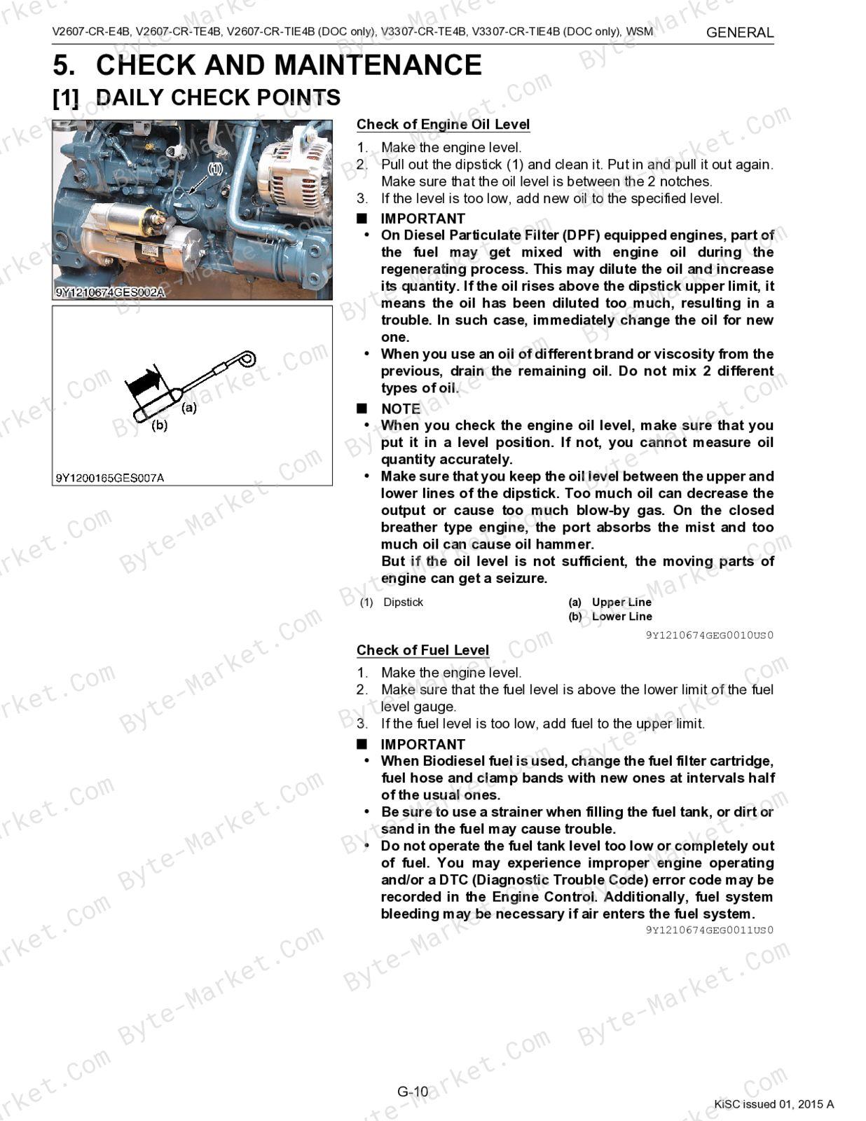
- CHECK AND MAINTENANCE — p. G-10
- [1] DAILY CHECK POINTS — p. G-10
- [2] INITIAL 50 HOURS — p. G-13
- [3] EVERY 50 HOURS — p. G-14
- [4] EVERY 250 HOURS — p. G-14
- [5] EVERY 500 HOURS — p. G-16
- [6] EVERY 1000 HOURS — p. G-20
- [7] EVERY 1500 HOURS — p. G-21
- [8] EVERY 3000 HOURS — p. G-23
- [9] EVERY 1 YEAR — p. G-30
- [10]EVERY 2 YEARS — p. G-31
- SPECIAL TOOLS — p. G-36
- ENGINE BODY — p. 1-M1
- [1] CYLINDER BLOCK — p. 1-M1
- [2] COOLING JACKET — p. 1-M1
- [3] HALF-FLOATING HEAD COVER — p. 1-M2
- [4] CYLINDER HEAD — p. 1-M3
- [5] 4 SCREWS PER EACH CYLINDER ASSEMBLING STRUCTURE — p. 1-M4
- [6] CENTER DIRECT INJECTION SYSTEM (E-CDIS) — p. 1-M5
- [7] GEAR TRAIN CONFIGURATION — p. 1-M5
- [8] PISTON — p. 1-M6
- LUBRICATING SYSTEM — p. 1-M7
- [1] OIL COOLER — p. 1-M7
- COOLING SYSTEM — p. 1-M8
- [1] THERMOSTAT — p. 1-M8
- [2] BOTTOM BYPASS SYSTEM — p. 1-M9
- FUEL SYSTEM — p. 1-M10
- [1] OVERVIEW — p. 1-M10
- [2] SUPPLY PUMP — p. 1-M11
- [3] RAIL — p. 1-M14
- [4] INJECTOR — p. 1-M15
- [5] ENGINE CONTROL SYSTEM — p. 1-M18
- (1) Engine ECU — p. 1-M19
- (2) Sensor — p. 1-M19
- (1) Engine ECU — p. 1-M19
- EGR SYSTEM — p. 1-M21
- [1] EGR VALVE — p. 1-M21
- [2] REED VALVE — p. 1-M21
- [3] EGR COOLER — p. 1-M22
- AFTER TREATMENT SYSTEM — p. 1-M23
- V3307-CR-TE4B] — p. 1-M23
- AFTER TREATMENT SYSTEM — p. 1-M23
- [2] AFTER TREATMENT DEVICES [V2607-CR-TIE4B / V3307-CR-TIE4B] — p. 1-M29
- TROUBLESHOOTING — p. 1-S1
- SERVICING SPECIFICATIONS — p. 1-S5
- TIGHTENING TORQUES — p. 1-S14
- [1] TIGHTENING TORQUES OF SCREWS, BOLTS AND NUTS FOR GENERAL USE — p. 1-S14
- [2] TIGHTENING TORQUES OF SCREWS, BOLTS AND NUTS FOR SPECIAL USE — p. 1-S15
- CHECKING, DISASSEMBLING AND SERVICING — p. 1-S18
- [1] CHECKING AND ADJUSTING — p. 1-S18
- (1) Engine Body — p. 1-S18
- (2) Lubricating System — p. 1-S20
- (3) Cooling System — p. 1-S20
- (4) Electrical System — p. 1-S22
- (5) Turbocharger — p. 1-S26
- [2] DISASSEMBLING AND ASSEMBLING — p. 1-S27
- (1) Draining Engine Oil and Coolant — p. 1-S27
- (2) External Components — p. 1-S28
- (3) Turbocharger and EGR — p. 1-S41
- (4) Common Rail — p. 1-S42
- (5) Cylinder Head and Valves — p. 1-S44
- (6) Thermostat — p. 1-S51
- (7) Supply Pump — p. 1-S52
- (8) Water Pump and Oil Cooler — p. 1-S55
- (9) Front Cover — p. 1-S56
- (10)Flywheel and Timing Gears — p. 1-S57
- (11)Piston and Connecting Rod — p. 1-S64
- (12)Crankshaft and Crankcase — p. 1-S68
- (13)Starter — p. 1-S70
- (14)Alternator — p. 1-S71
- [3] SERVICING — p. 1-S73
- (1) Cylinder Head and Valves — p. 1-S73
- (2) Timing Gears — p. 1-S82
- (3) Piston and Connecting Rod — p. 1-S87
- (4) Crankshaft — p. 1-S91
- (5) Cylinder — p. 1-S97
- (6) Oil Pump — p. 1-S98
- (7) Relief Valve — p. 1-S99
- (8) Starter — p. 1-S99
- (9) Alternator — p. 1-S101
Capabilities
The source outline indexes disassembly and assembly, checking and adjustment, maintenance tasks, troubleshooting, and servicing instructions. Use these source-backed headings to locate the applicable task or system in the source PDF, then confirm model-specific notes, specifications, illustrations, and operating conditions at the relevant page before carrying out service work.
Keep the source's safety sequence, prerequisite steps, labels, units, configuration notes, and footnotes with the selected task; do not apply an isolated value outside the conditions stated in the manual.
Technical reference
Reference tables include torque settings and wear limits for service checks, adjustment work, and specification lookup. Use the values and conditions in the PDF for the applicable model and procedure.
- Service limits and settings: torque settings and wear limits.
Delivery
This manual is supplied as a digital PDF file and is available for instant download after purchase. No physical media is shipped.
References
Kubota Workshop Manual for Engine, document code 9Y111-06744, PDF edition.


No questions found.