
About this manual
Kubota's Workshop Manual groups information for the covered tractors by system. The model list appears in Manual details.
Use the Manual Contents below to check that the exact repair, inspection, or maintenance procedure you need is included in this publication.
Manual details
- Manufacturer
- Kubota
- Manual type
- Workshop Manual
- Equipment type
- Tractor
- Models
- M6060 and M7060
- Document number
- 9Y111-08268
- KiSC issue / revision
- December 2021 (A)
- Text search
- Available on pages with a text layer
- PDF navigation
- Interactive contents links and PDF bookmarks
- Image and font quality
- Original PDF quality preserved; supplied without recompression
Revision history
Source-recorded revision entries (physical PDF page 3):
- Code No. last digit 1 — October 2013: Front axle section is revised; Error correction.
- Code No. last digit 2 — February 2015: DPF regeneration system changed.
- Code No. last digit 3 — March 2015: PTO clutch disassembling method; Revised 3P control valve spool length.
- Code No. last digit 4 — April 2017: Maintenance interval was introduced; CCV heater equipped model was introduced. Assembling and disassembling process in ENGINE was revised and some wiring diagrams, electrical circuits and components are added in ELECTRICAL SYSTEM.
- Code No. last digit 5 — November 2019: Changed the Safety decals; Correction of engine compression pressure specification; Corrected assembly procedure of the 1st shaft (F8/R8 speed transmission model); Corrected the control valve adjustment length "L1".
- Code No. last digit 6 — February 2020: Added remarks to error code "ERROR-25".
- Code No. last digit 7 — August 2020: Additional information; Tightening torques for the cylinder head mounting screw were changed.
- Code No. last digit 8 — December 2021: The procedure of “Changing front axle gear case oil and front differential case oil” was corrected.
Product highlights
Electrical systems
The manual includes wiring diagrams and electrical troubleshooting.
Hydraulic systems
The manual includes hydraulic pressure-test material and hydraulic valve-adjustment material.
Specifications and settings
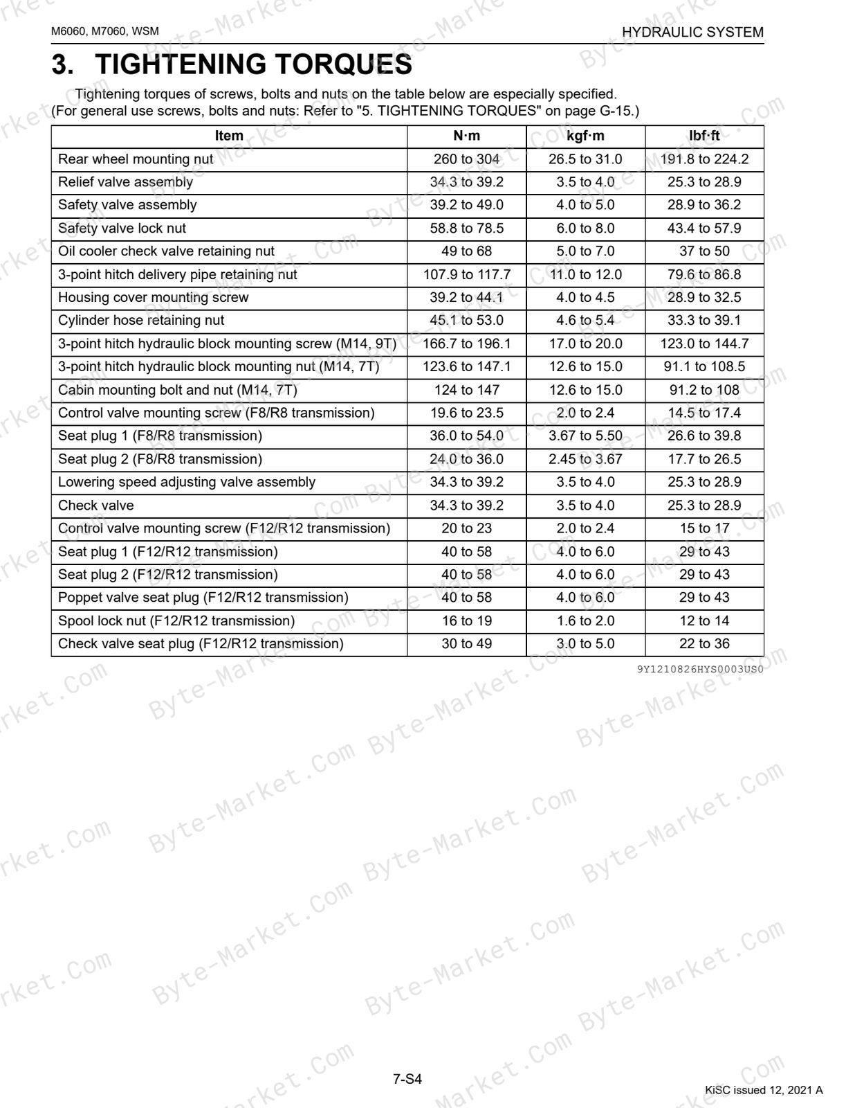
The manual includes reference information for torque specifications, wear limits, clearances, capacities, dimensions, and speed ratings.
Special tools
A special-tools section is included.
Maintenance
The manual includes a maintenance schedule.
Applicability and limitations
For the diesel engine / tractor mechanism not included here, the reader refers to Workshop Manual (Code No. 9Y021-01870 / 9Y021-18200).
For servicing of Common Rail System (CRS), the reader refers to DIAGNOSIS MANUAL (9Y120-02440).
For servicing of Diesel Particulate Filter (DPF), the reader refers to DIESEL PARTICULATE FILTER HANDLING MANUAL (9Y111-08131).
Manual contents
Use these source headings to locate the task or system you need in the PDF.
- TO THE READER — p. 2
- I INFORMATION — p. 4
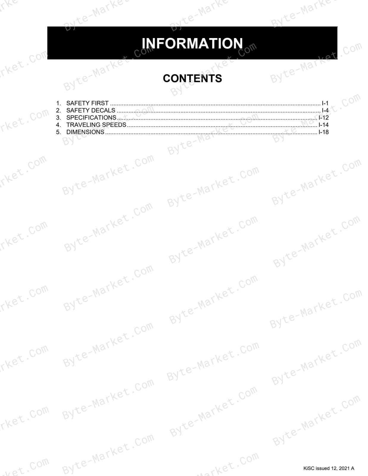
- INFORMATION — p. 5
- 1. SAFETY FIRST — p. 6
- 2. SAFETY DECALS — p. 9
- 3. SPECIFICATIONS — p. 17
- 4. TRAVELING SPEEDS — p. 19
- 5. DIMENSIONS — p. 23
- INFORMATION — p. 5
- G GENERAL — p. 25
- GENERAL — p. 26
- 1. TRACTOR IDENTIFICATION — p. 28
- [1] MODEL NAME AND SERIAL NUMBERS — p. 28
- (1) ROPS Model — p. 28
- (2) CABIN Model — p. 29
- (3) Engine Serial Number — p. 30
- (4) DPF Muffler Number — p. 31
- [2] E4B ENGINE — p. 33
- [3] CYLINDER NUMBER — p. 33
- [1] MODEL NAME AND SERIAL NUMBERS — p. 28
- 2. GENERAL PRECAUTIONS — p. 34
- 3. HANDLING PRECAUTIONS FOR ELECTRICAL PARTS AND WIRING — p. 35
- [1] WIRING — p. 35
- [2] BATTERY — p. 37
- [3] FUSE — p. 37
- [4] CONNECTOR — p. 37
- [5] HANDLING OF CIRCUIT TESTER — p. 38
- [6] COLOR OF WIRING — p. 39
- 4. LUBRICANTS, FUEL AND COOLANT — p. 40
- 5. TIGHTENING TORQUES — p. 42
- [1] GENERAL USE SCREWS, BOLTS AND NUTS — p. 42
- [2] STUD BOLTS — p. 42
- [3] HYDRAULIC FITTINGS — p. 43
- (1) Hydraulic Hose Fittings — p. 43
- (2) Hydraulic Pipe Cap Nuts — p. 43
- (3) Adaptors, Elbows and Others — p. 43
- [4] METRIC SCREWS, BOLTS AND NUTS — p. 44
- [5] AMERICAN STANDARD SCREWS, BOLTS AND NUTS WITH UNC OR UNF THREADS — p. 44
- [6] PLUGS — p. 44
- 6. MAINTENANCE — p. 45
- 7. CHECK AND MAINTENANCE — p. 48
- [1] DAILY CHECK — p. 48
- [2] CHECK POINTS OF INITIAL 50 HOURS — p. 49
- [3] CHECK POINTS OF EVERY 50 HOURS — p. 50
- [4] CHECK POINTS OF EVERY 100 HOURS — p. 52
- [5] CHECK POINTS OF EVERY 200 HOURS — p. 57
- [6] CHECK POINTS OF EVERY 400 HOURS — p. 58
- [7] CHECK POINTS OF EVERY 500 HOURS — p. 59
- [8] CHECK POINTS OF EVERY 600 HOURS — p. 61
- [9] CHECK POINT OF EVERY 1000 HOURS — p. 62
- [10] CHECK POINTS OF EVERY 1500 HOURS — p. 64
- [11] CHECK POINTS OF EVERY 3000 HOURS — p. 65
- [12] CHECK POINTS OF EVERY 1 YEAR — p. 65
- [13] CHECK POINTS OF EVERY 1000 HOURS OR 1 YEAR — p. 66
- [14] CHECK POINTS OF EVERY 2 YEARS — p. 66
- [15] CHECK POINTS OF EVERY 2000 HOURS OR 2 YEARS — p. 67
- [16] CHECK POINTS OF EVERY 4 YEARS — p. 69
- [17] OTHERS — p. 70
- 8. SPECIAL TOOLS — p. 77
- [1] SPECIAL TOOLS FOR ENGINE — p. 77
- [2] SPECIAL TOOLS FOR TRACTOR — p. 97
- [3] SPECIAL TOOLS FOR AIR CONDITIONER UNIT — p. 114
- 9. TIRES — p. 117
- [1] TIRE SIZE AND INFLATION PRESSURE — p. 117
- [2] TREAD ADJUSTMENT — p. 118
- (1) Front Wheels [2WD Model] — p. 118
- (2) Front Wheels [4WD Model] — p. 119
- (3) Rear Wheels — p. 120
- [3] WHEEL HUB — p. 120
- [4] TIRE LIQUID INJECTION — p. 121
- 10. IMPLEMENT LIMITATIONS — p. 124
- 1. TRACTOR IDENTIFICATION — p. 28
- GENERAL — p. 26
- 1 ENGINE — p. 127
- MECHANISM — p. 128
- 1. FEATURE — p. 129
- 2. ENGINE BODY — p. 130
- [1] CYLINDER BLOCK — p. 130
- [2] COOLING JACKET — p. 130
- [3] HALF-FLOATING HEAD COVER — p. 131
- [4] CYLINDER HEAD — p. 131
- [5] 4 SCREWS PER EACH CYLINDER ASSEMBLING STRUCTURE — p. 132
- [6] CENTER DIRECT INJECTION SYSTEM (E-CDIS) — p. 133
- [7] GEAR TRAIN CONFIGURATION — p. 133
- [8] PISTON — p. 134
- [9] BUILT-IN DYNAMIC BALANCER — p. 134
- 3. LUBRICATING SYSTEM — p. 135
- [1] OIL COOLER — p. 135
- 4. COOLING SYSTEM — p. 136
- [1] THERMOSTAT — p. 136
- [2] BOTTOM BYPASS SYSTEM — p. 137
- 5. FUEL SYSTEM — p. 138
- [1] OVERVIEW — p. 138
- [2] SUPPLY PUMP — p. 139
- [3] RAIL — p. 142
- [4] INJECTOR — p. 143
- [5] ENGINE CONTROL SYSTEM — p. 146
- (1) Engine ECU — p. 147
- (2) Sensor — p. 147
- 6. EGR SYSTEM — p. 149
- [1] EGR VALVE — p. 149
- [2] REED VALVE — p. 149
- [3] EGR COOLER — p. 150
- 7. AFTER TREATMENT SYSTEM — p. 151
- [1] CONTROL SYSTEM DIAGRAM — p. 151
- [2] DPF REGENERATION SYSTEM (INHIBIT VERSION) — p. 152
- (1) Regeneration Mode (Inhibit Version) — p. 152
- (2) PM Warning Level (Inhibit Version) — p. 153
- [3] DPF REGENERATION SYSTEM (Default Version) — p. 155
- (1) Regeneration Mode (Default Version) — p. 155
- (2) PM Warning Level (Default Version) — p. 156
- SERVICING — p. 161
- 1. TROUBLESHOOTING — p. 162
- 2. SERVICING SPECIFICATIONS — p. 165
- 3. TIGHTENING TORQUES — p. 170
- 4. CHECKING, DISASSEMBLING AND SERVICING — p. 172
- [1] CHECKING AND ADJUSTING — p. 172
- (1) Engine Body — p. 172
- (2) Lubricating System — p. 174
- (3) Cooling System — p. 175
- (4) Turbocharger — p. 177
- (5) EGR Cooler — p. 178
- [2] PREPARATION — p. 179
- (1) Bonnet and Cover — p. 179
- (2) DPF Muffler — p. 180
- (3) Lubricant and Coolant — p. 183
- (4) Propeller Shaft and Power Steering Hose — p. 184
- (5) Separating Engine From Clutch Housing (ROPS Model) — p. 185
- (6) Separating Engine From Clutch Housing (CABIN Model) — p. 187
- (7) Separating Engine From Front Axle Frame — p. 190
- [3] DISASSEMBLING AND ASSEMBLING — p. 191
- (1) External Components — p. 191
- (2) Turbocharger and EGR — p. 191
- (3) Common Rail — p. 193
- (4) Cylinder Head and Valves — p. 195
- (5) Thermostat — p. 201
- (6) Supply Pump — p. 202
- (7) Water Pump and Oil Cooler — p. 205
- (8) Front Cover — p. 206
- (9) Flywheel and Timing Gears — p. 207
- (10) Piston and Connecting Rod — p. 212
- (11) Crankshaft and Crankcase — p. 215
- [4] SERVICING — p. 217
- (1) Cylinder Head and Valves — p. 217
- (2) Timing Gears — p. 223
- (3) Piston and Connecting Rod — p. 229
- (4) Crankshaft — p. 231
- (5) Cylinder — p. 237
- (6) Oil Pump — p. 237
- (7) Relief Valve — p. 238
- (8) CCV Heater Kit (If Equipped) — p. 239
- [1] CHECKING AND ADJUSTING — p. 172
- MECHANISM — p. 128
- 2 TRANSMISSION — p. 240
- MECHANISM — p. 241
- 1. STRUCTURE — p. 242
- [1] F8/R8 SPEED TRANSMISSION MODEL (2WD) — p. 242
- [2] F8/R8 SPEED TRANSMISSION MODEL (4WD) — p. 243
- [3] F12/R12 SPEED TRANSMISSION MODEL (4WD) — p. 244
- 2. POWER TRAIN FOR TRAVELING GEAR — p. 245
- [1] SHUTTLE SHIFT SECTION — p. 245
- (1) Structure — p. 245
- (2) Oil Flow — p. 246
- (3) Hydraulic Clutch Pack — p. 247
- [2] HYDRAULIC SHUTTLE VALVE — p. 248
- (1) Structure — p. 248
- (2) Operation — p. 249
- [3] MAIN GEAR SHIFT SECTION — p. 254
- (1) F8/R8 Speed Transmission Model — p. 254
- (2) F12/R12 Speed Transmission Model — p. 255
- [4] HI-LO-CREEP SHIFT SECTION (OPTION) — p. 256
- (1) F8/R8 Speed Transmission Model — p. 256
- (2) F12/R12 Speed Transmission Model — p. 257
- [5] SHIFT FORK ROD AND FORK — p. 258
- (1) F8/R8 Speed Transmission Model — p. 258
- (2) F12/R12 Speed Transmission Model — p. 259
- [1] SHUTTLE SHIFT SECTION — p. 245
- 3. LUBRICATION FOR TRANSMISSION — p. 260
- [1] HYDRAULIC SHUTTLE MODEL — p. 260
- (1) F8/R8 Speed Transmission Model — p. 260
- (2) F12/R12 Speed Transmission Model — p. 261
- [1] HYDRAULIC SHUTTLE MODEL — p. 260
- 4. POWER TRAIN FOR PTO SYSTEM — p. 262
- [1] PTO GEAR SECTION — p. 262
- [2] PTO HYDRAULIC CLUTCH SECTION — p. 263
- (1) PTO Hydraulic Clutch — p. 263
- (2) PTO Solenoid Valve, Relief Valve And Oil Flow — p. 264
- 5. POWER TRAIN FOR 4WD — p. 265
- [1] 4WD SHIFT SECTION (F8/R8 SPEED TRANSMISSION MODEL) — p. 265
- (1) 2WD-4WD Section — p. 265
- (2) 2WD-4WD Shift Linkage — p. 266
- [2] 4WD HYDRAULIC CLUTCH SECTION (F12/R12 SPEED TRANSMISSION MODEL) — p. 267
- (1) 4WD Clutch — p. 267
- (2) 4WD Oil Flow — p. 268
- [1] 4WD SHIFT SECTION (F8/R8 SPEED TRANSMISSION MODEL) — p. 265
- 1. STRUCTURE — p. 242
- SERVICING — p. 269
- 1. TROUBLESHOOTING — p. 271
- 2. SERVICING SPECIFICATIONS — p. 273
- 3. TIGHTENING TORQUES — p. 276
- 4. CHECKING AND ADJUSTING — p. 277
- [1] SHUTTLE LEVER — p. 277
- (1) Shuttle Lever Neutral Position — p. 277
- (2) Engine Start Condition — p. 279
- [2] CLUTCH PEDAL FREE TRAVEL — p. 280
- [3] GEAR SHIFTING LINKAGE — p. 281
- (1) Main Gear Shift — p. 281
- (2) Range/Creep Gear Shift — p. 284
- [4] SHUTTLE VALVE — p. 287
- [5] 2WD-4WD CLUTCH (F12/R12 SPEED TRANSMISSION MODEL) — p. 288
- [6] PTO CLUTCH — p. 289
- [7] ACCELERATOR SECTION — p. 290
- (1) Checking Accelerator Lever — p. 290
- (2) Adjusting Accelerator Lever and Wire — p. 292
- [1] SHUTTLE LEVER — p. 277
- 5. DISASSEMBLING AND ASSEMBLING — p. 294
- [1] HYDRAULIC SHUTTLE VALVE AND SOLENOID VALVE ASSEMBLY — p. 294
- (1) Removing Fuel Tank (ROPS Model) — p. 294
- (2) Removing Fuel Tank (CABIN Model) — p. 294
- (3) Hydraulic Shuttle Valve — p. 296
- (4) Solenoid Valve Assembly — p. 297
- [2] PREPARATION FOR SEPARATING EACH BLOCK — p. 298
- (1) Lubricant and Coolant — p. 298
- (2) 4WD Propeller Shaft and Power Steering Hose — p. 298
- (3) Front Axle Rocking Restrictor — p. 299
- (4) Bonnet (ROPS Model) — p. 299
- (5) Bonnet (CABIN Model) — p. 299
- [3] SEPARATING ENGINE AND CLUTCH HOUSING CASE — p. 299
- (1) ROPS Model — p. 299
- (2) CABIN Model — p. 299
- [4] SEPARATING CLUTCH HOUSING CASE FROM TRANSMISSION CASE — p. 300
- (1) Preparation for ROPS Model — p. 300
- (2) Preparation for CABIN Model — p. 304
- (3) Separating Transmission Case — p. 306
- [5] SEPARATING TRANSMISSION CASE — p. 306
- [6] DAMPER DISC — p. 307
- [7] HYDRAULIC SHUTTLE CLUTCH — p. 307
- [8] SHIFT COVER — p. 310
- [9] CLUTCH HOUSING — p. 314
- (1) Creep Gear Assembly (If Equipped) — p. 314
- (2) 1st Shaft, 2nd Shaft and 3rd Shaft — p. 314
- (3) 1st Shaft — p. 317
- (4) 2nd Shaft — p. 319
- (5) 3rd Shaft — p. 320
- (6) Removing DT Propeller Shaft — p. 321
- [10] TRANSMISSION CASE — p. 322
- (1) Removing Solenoid Valve Assembly — p. 322
- (2) PTO Clutch Pack — p. 323
- (3) Disassembling PTO Clutch Pack — p. 324
- (4) Removing 4WD Clutch (F12/R12 Speed Transmission Model) — p. 325
- (5) Disassembling 4WD Clutch Pack (F12/R12 Speed Transmission Model) — p. 327
- (6) Removing Differential Gear and Bevel Pinion Shaft — p. 328
- [11] DIFFERENTIAL GEAR — p. 331
- [12] PTO GEAR CASE — p. 333
- [1] HYDRAULIC SHUTTLE VALVE AND SOLENOID VALVE ASSEMBLY — p. 294
- 6. SERVICING — p. 335
- [1] BEARING, SHIFT FORK AND SYNCHRONIZER — p. 335
- [2] TRAVELING CLUTCH — p. 336
- [3] SHUTTLE CLUTCH PACK — p. 337
- [4] SHAFT AND GEAR — p. 337
- [5] 4WD CLUTCH PACK (F12/R12 SPEED TRANSMISSION MODEL) — p. 338
- [6] PTO CLUTCH PACK — p. 339
- [7] DIFFERENTIAL GEAR — p. 340
- (1) Spiral Bevel Pinion Shaft — p. 340
- (2) Backlash and Tooth Contact — p. 341
- (3) Differential Case Differential Pinion Gear and Differential Side Gear — p. 343
- (4) Differential Lock Shifter — p. 344
- MECHANISM — p. 241
- 3 REAR AXLE — p. 345
- MECHANISM — p. 346
- 1. FEATURES — p. 347
- SERVICING — p. 348
- 1. TROUBLESHOOTING — p. 349
- 2. SERVICING SPECIFICATIONS — p. 350
- 3. TIGHTENING TORQUES — p. 351
- 4. DISASSEMBLING AND ASSEMBLING — p. 352
- [1] PREPARATION FOR DISASSEMBLING AND ASSEMBLING VALVE — p. 352
- [2] SEPARATING REAR AXLE (ROPS MODEL) — p. 353
- [3] SEPARATING REAR AXLE (CABIN MODEL) — p. 355
- [4] DISASSEMBLING REAR AXLE — p. 358
- (1) Brake Section — p. 358
- (2) Rear Axle Case — p. 358
- 5. SERVICING — p. 361
- [1] BEARING — p. 361
- [2] PLANETARY GEAR — p. 361
- MECHANISM — p. 346
- 4 BRAKES — p. 363
- MECHANISM — p. 364
- 1. TRAVELLING BRAKE — p. 365
- [1] STRUCTURE (HYDRAULIC BRAKE MODEL) — p. 365
- [2] STRUCTURE (MECHANICAL BRAKE MODEL) — p. 367
- [3] MASTER CYLINDER ASSEMBLY — p. 368
- [4] HYDRAULIC TRAILER BRAKE VALVE — p. 369
- (1) Structure — p. 369
- (2) Operation — p. 370
- 2. PARKING BRAKE (F12/R12 MODEL) — p. 374
- [1] INNER STRUCTURE — p. 374
- [2] FIXING FLOW — p. 375
- 1. TRAVELLING BRAKE — p. 365
- SERVICING — p. 377
- 1. TROUBLESHOOTING — p. 378
- 2. SERVICING SPECIFICATIONS — p. 379
- 3. TIGHTENING TORQUES — p. 380
- 4. CHECKING, DISASSEMBLING AND SERVICING — p. 381
- [1] CHECKING AND ADJUSTING — p. 381
- (1) Traveling Brake — p. 381
- (2) Parking Brake (F12/R12 Model) — p. 384
- [2] DISASSEMBLING AND ASSEMBLING — p. 386
- (1) Preparation for Disassembling Master Cylinder and Brake Pedal (ROPS Model) — p. 386
- (2) Preparation for Disassembling Master Cylinder and Brake Pedal (CABIN Model) — p. 387
- (3) Removing Master Cylinder (ROPS Model) — p. 389
- (4) Removing Master Cylinder (CABIN Model) — p. 389
- (5) Master Cylinder — p. 390
- (6) Brake Pedal — p. 391
- (7) Brake Piston — p. 392
- (8) Brake Disk and Plate — p. 393
- (9) Parking Brake Gear (F12/R12) — p. 395
- [3] SERVICING — p. 396
- (1) Brake Pedal — p. 396
- (2) Traveling Brake — p. 397
- [1] CHECKING AND ADJUSTING — p. 381
- MECHANISM — p. 364
- 5 FRONT AXLE — p. 398
- MECHANISM — p. 399
- 1. STRUCTURE — p. 400
- [1] 2 WHEEL DRIVE — p. 400
- [2] 4 WHEEL DRIVE — p. 401
- [3] LIMITED SLIP DIFFERENTIAL (LSD) — p. 402
- 1. STRUCTURE — p. 400
- SERVICING — p. 403
- 1. TROUBLESHOOTING — p. 404
- 2. SERVICING SPECIFICATIONS — p. 405
- 3. TIGHTENING TORQUES — p. 408
- 4. CHECKING, DISASSEMBLING AND SERVICING — p. 409
- [1] CHECKING AND ADJUSTING — p. 409
- [2] DISASSEMBLING AND ASSEMBLING — p. 411
- (1) Separating Front Axle [2WD Model] — p. 411
- (2) Separating Front Axle [4WD Model] — p. 411
- (3) Disassembling Front Axle [2WD Model] — p. 413
- (4) Disassembling Front Axle [4WD Model] — p. 415
- (5) Removing Differential Gear and Bevel Pinion Shaft — p. 417
- (6) Disassembling Differential Gear (LSD) — p. 418
- [3] SERVICING — p. 420
- (1) 2WD Model — p. 420
- (2) 4WD Model — p. 421
- MECHANISM — p. 399
- 6 STEERING — p. 430
- MECHANISM — p. 431
- 1. STEERING MECHANISM — p. 432
- 2. STEERING CYLINDER — p. 433
- SERVICING — p. 434
- 1. TROUBLESHOOTING — p. 435
- 2. SERVICING SPECIFICATIONS — p. 436
- 3. TIGHTENING TORQUES — p. 437
- 4. CHECKING, DISASSEMBLING AND SERVICING — p. 438
- [1] CHECKING AND ADJUSTING — p. 438
- (1) Steering Controller — p. 438
- (2) Hydraulic Pump — p. 438
- [2] PREPARATION — p. 439
- (1) Removing Power Steering Hydraulic Pump — p. 439
- (2) Removing Steering Wheel — p. 439
- (3) Removing Power Steering Controller (ROPS Model) — p. 439
- (4) Removing Steering Controller (CABIN Model) — p. 440
- (5) Removing Power Steering Cylinder (2WD Model) — p. 441
- (6) Removing Steering Cylinder (4WD Model) — p. 443
- [3] DISASSEMBLING AND ASSEMBLING — p. 445
- (1) Hydraulic Pump — p. 445
- (2) Steering Controller — p. 445
- (3) Disassembling Steering Cylinder — p. 448
- [4] SERVICING — p. 449
- [1] CHECKING AND ADJUSTING — p. 438
- MECHANISM — p. 431
- 7 HYDRAULIC SYSTEM — p. 450
- MECHANISM — p. 451
- 1. STRUCTURE — p. 452
- [1] F8/R8 SPEED TRANSMISSION MODEL (ROPS MODEL) — p. 452
- [2] F8/R8 SPEED TRANSMISSION MODEL (CABIN MODEL) — p. 453
- [3] F12/R12 SPEED TRANSMISSION MODEL (ROPS MODEL) — p. 454
- [4] F12/R12 SPEED TRANSMISSION MODEL (CABIN MODEL) — p. 455
- 2. HYDRAULIC CIRCUIT — p. 457
- [1] TOTAL HYDRAULIC CIRCUIT — p. 457
- (1) F8/R8 Speed Transmission Model — p. 457
- (2) F12/R12 Speed Transmission Model — p. 458
- [1] TOTAL HYDRAULIC CIRCUIT — p. 457
- 3. THREE POINT HITCH HYDRAULIC SYSTEM — p. 459
- [1] THREE POINT HITCH HYDRAULIC CIRCUIT — p. 459
- [2] HYDRAULIC BLOCK — p. 460
- [3] LINKAGE MECHANISM — p. 461
- (1) Position Control — p. 462
- (2) Draft Control — p. 463
- (3) Mixed Control — p. 465
- [4] HYDRAULIC CYLINDER — p. 465
- 1. STRUCTURE — p. 452
- SERVICING — p. 466
- 1. TROUBLESHOOTING — p. 467
- 2. SERVICING SPECIFICATIONS — p. 468
- 3. TIGHTENING TORQUES — p. 470
- 4. CHECKING AND ADJUSTING — p. 471
- [1] HYDRAULIC PUMP — p. 471
- [2] RELIEF AND SAFETY VALVE — p. 473
- [3] POSITION AND DRAFT CONTROL LINKAGE — p. 475
- [4] AUXILIARY CONTROL VALVE LINKAGE — p. 482
- [5] OIL COOLER CHECK VALVE (FOR F12/R12 SPEED TRANSMISSION MODEL) — p. 483
- 5. DISASSEMBLING AND ASSEMBLING — p. 484
- [1] HYDRAULIC PUMP — p. 484
- [2] THREE POINT HITCH HYDRAULIC BLOCK ASSEMBLY — p. 485
- (1) Removing 3-point Hitch Hydraulic Block (ROPS Model) — p. 485
- (2) Removing 3-point Hitch Hydraulic Block (CABIN Model) — p. 486
- [3] HYDRAULIC LINKAGE — p. 487
- [4] CONTROL VALVE — p. 491
- (1) Control Valve (For F8/R8 transmission) — p. 491
- (2) Control Valve (For F12/R12 transmission) — p. 493
- [5] HYDRAULIC CYLINDER — p. 495
- [6] RELIEF VALVE — p. 497
- [7] SAFETY VALVE — p. 497
- [8] TOP LINK BRACKET — p. 498
- [9] LIFT ARM AND LIFT ARM SHAFT — p. 498
- [10] LOWERING SPEED ADJUSTING VALVE AND CHECK VALVE — p. 499
- 6. SERVICING — p. 500
- [1] LIFT ARM AND TOP LINK BRACKET — p. 500
- MECHANISM — p. 451
- 8 ELECTRICAL SYSTEM — p. 502
- MECHANISM — p. 503
- 1. ELECTRICAL CIRCUIT DIAGRAM — p. 504
- [1] ROPS MODEL — p. 504
- (1) Starting System and Charging System — p. 504
- (2) Lighting System — p. 505
- (3) Instrument Panel Board (Meter Panel) — p. 506
- (4) Main Control System (Tractor ECU) (R8/F8 Model) — p. 507
- (5) Main Control System (Tractor ECU) (R12/F12 Model) — p. 508
- (6) Engine Control System 1 (Engine ECU) — p. 509
- (7) Engine Control System 2 (Engine ECU) — p. 510
- [1] ROPS MODEL — p. 504
- 2. STARTING SYSTEM — p. 511
- [1] SYSTEM OUTLINE AND ELECTRICAL CIRCUIT — p. 511
- (1) ROPS Model — p. 511
- (2) CABIN Model — p. 512
- [1] SYSTEM OUTLINE AND ELECTRICAL CIRCUIT — p. 511
- 3. INSTRUMENT PANEL — p. 513
- [1] INDICATION ITEMS OF METER PANEL — p. 513
- (1) ROPS Model — p. 513
- (2) CABIN Model — p. 514
- [2] EASY CHECKER™ — p. 515
- [3] LCD MONITOR INDICATION — p. 516
- (1) ERROR Mode — p. 517
- (2) Setting Mode — p. 518
- (3) Testing Mode — p. 518
- [4] ECO 40 km/h FUNCTION — p. 519
- (1) Structure — p. 519
- (2) Components — p. 520
- [5] PTO SPEED LIMITER (IF EQUIPPED 540ECONOMY) — p. 521
- (1) Structure — p. 521
- (2) Components — p. 522
- [6] CONSTANT RPM MANAGEMENT SWITCH WITH INDICATOR (WORK CRUISE) — p. 524
- (1) Structure — p. 524
- [1] INDICATION ITEMS OF METER PANEL — p. 513
- 4. LIGHTING SYSTEM — p. 525
- [1] COMPONENTS — p. 525
- (1) Flasher Unit — p. 525
- [1] COMPONENTS — p. 525
- 5. TRAILER SOCKET — p. 526
- 1. ELECTRICAL CIRCUIT DIAGRAM — p. 504
- SERVICING — p. 527
- 1. TROUBLESHOOTING — p. 528
- 2. SERVICING SPECIFICATIONS — p. 533
- 3. TIGHTENING TORQUES — p. 534
- 4. CHECKING AND ADJUSTING — p. 535
- [1] BATTERY, FUSES, GROUNDING AND CONNECTOR — p. 535
- (1) Battery — p. 535
- (2) Fuse — p. 537
- (3) Checking Grounding Wires — p. 540
- (4) Connector — p. 541
- [2] MAIN SWITCH — p. 541
- (1) ROPS Model — p. 541
- (2) CABIN Model — p. 542
- [3] GLOW PLUG — p. 544
- [4] STARTER MOTOR — p. 544
- [5] ALTERNATOR — p. 545
- [6] THROTTLE SENSOR — p. 547
- [7] METER PANEL — p. 549
- (1) Setting Mode — p. 549
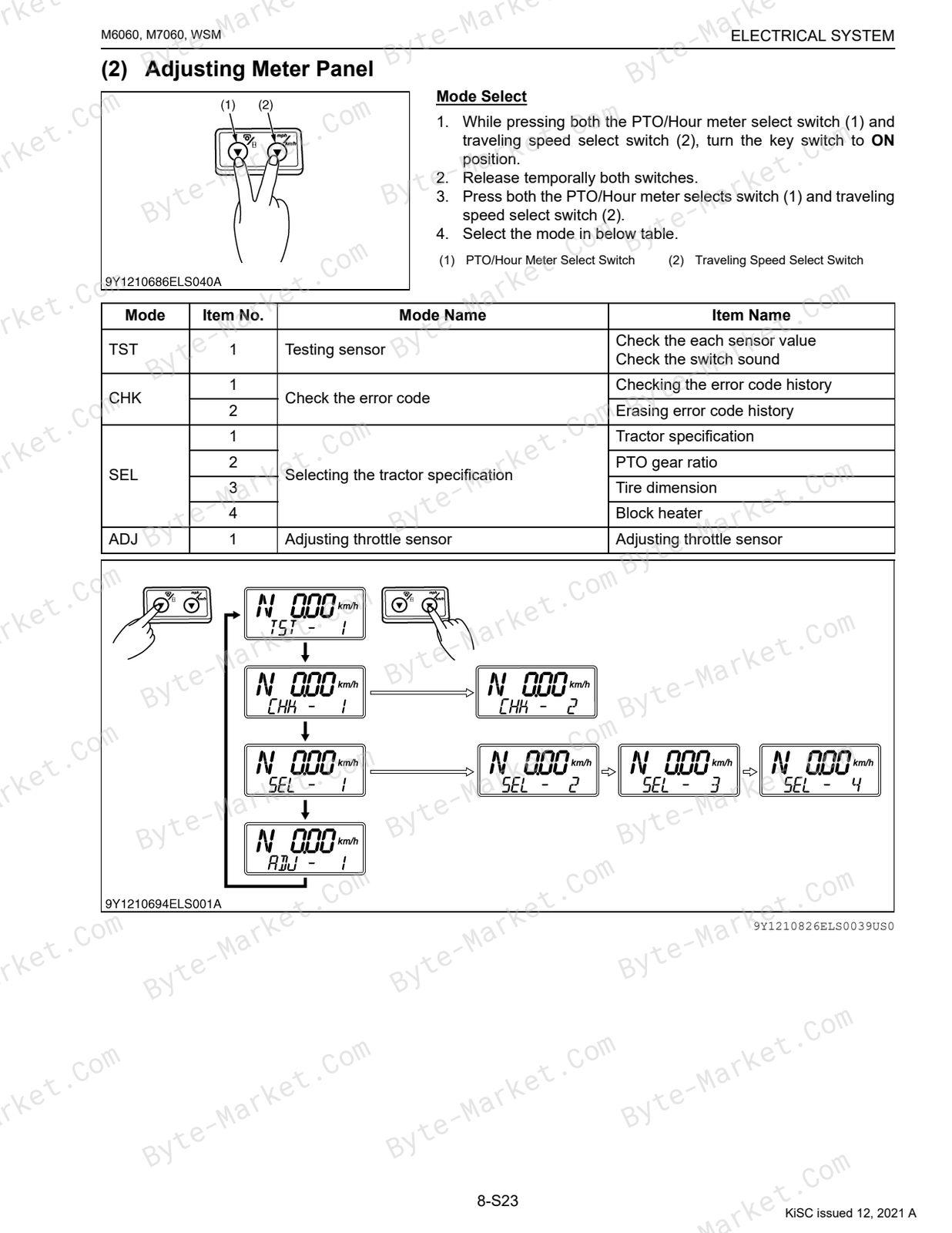
- (2) Adjusting Meter Panel — p. 550
- (3) Adjusting Throttle Sensor — p. 551
- (4) Testing Mode — p. 553
- (5) Checking Error Code — p. 554
- (6) Selecting Tractor Specification — p. 556
- [8] TRACTOR ECU — p. 559
- (1) Tractor ECU — p. 559
- (2) Connector Pin (44 Pin) — p. 561
- [9] TRAVELING SWITCH AND SENSOR — p. 562
- [10] ENGINE SENSOR — p. 567
- [11] RELAYS — p. 569
- (1) Starter Relay and Glow Relay — p. 569
- (2) Relays — p. 570
- [12] LIGHTING SWITCHES AND FLASHER UNIT — p. 572
- (1) Combination Switch (ROPS Model) — p. 572
- (2) Lever Combination Switch and Horn Switch (CABIN Model) — p. 573
- (3) Hazard Switch — p. 574
- (4) Flasher Unit — p. 575
- (5) Front Work Light Switch (ROPS Model) — p. 576
- (6) Front/Rear Work Light (CABIN Model) — p. 577
- [13] SOLENOID VALVE — p. 578
- (1) PTO — p. 578
- [14] OPC (OPERATOR PRESENCE CONTROL) SYSTEM — p. 579
- [1] BATTERY, FUSES, GROUNDING AND CONNECTOR — p. 535
- 5. DISASSEMBLING AND ASSEMBLING — p. 581
- [1] STARTER MOTOR — p. 581
- [2] ALTERNATOR — p. 581
- [3] FUSE (SLOW BLOW 100 A) FOR CABIN MODEL — p. 583
- 6. SERVICING — p. 584
- [1] STARTER — p. 584
- [2] ALTERNATOR — p. 586
- MECHANISM — p. 503
- 9 CABIN — p. 588
- MECHANISM — p. 589
- 1. AIR CONDIITIONING SYSTEM — p. 590
- [1] STRUCTURE — p. 590
- [2] COMPRESSOR — p. 591
- [3] AIR CONDITIONER UNIT — p. 592
- [4] SYSTEM CONTROL — p. 593
- [5] AIR FLOW — p. 594
- [6] AIR CONTROL VENT — p. 594
- [7] ELECTRICAL SYSTEM — p. 595
- (1) Electrical Circuit — p. 595
- (2) Blower Relay and Compressor Relay — p. 596
- (3) Blower Relay — p. 597
- 1. AIR CONDIITIONING SYSTEM — p. 590
- SERVICING — p. 598
- 1. TROUBLESHOOTING — p. 599
- 2. SERVICING SPECIFICATIONS — p. 603
- 3. TIGHTENING TORQUES — p. 604
- 4. PRECAUTIONS AT REPAIRING REFRIGERANT CYCLE — p. 605
- [1] HANDLING OF SERVICE TOOLS — p. 606
- (1) Manifold Gauge Set — p. 606
- (2) Refrigerant Charging Hose — p. 608
- (3) Vacuum Pump Adaptor — p. 609
- (4) Electric Gas Leak Tester — p. 609
- (5) Can Tap Valve — p. 609
- (6) T-joint — p. 610
- (7) R134a Refrigerant Recover and Recycling Machine — p. 610
- [1] HANDLING OF SERVICE TOOLS — p. 606
- 5. CHECKING AND CHARGING REFRIGERANT CYCLE — p. 611
- [1] CHECKING WITH MANIFOLD GAUGE — p. 611
- [2] DISCHARGING, EVACUATING AND CHARGING — p. 616
- (1) Discharging the Refrigerant — p. 616
- (2) Evacuating the System — p. 617
- (3) Charging the Refrigerant — p. 618
- (4) Checking Charge Refrigerant Amount — p. 620
- 6. CHECKING, DISASSEMBLING AND SERVICING — p. 621
- [1] CHECKING AND ADJUSTING — p. 621
- (1) Compressor — p. 621
- (2) Relay (A/C Compressor, Front Working Light, Front Wiper, Blower, Blower Hi, ACC, Auxiliary Power) — p. 621
- (3) Wiper Relay — p. 622
- (4) Control Panel (Blower Switch, A/C Switch, Mode Control Dial, Temperature Control Dial and Recirculation/Fresh Air Selection Switch) — p. 623
- (5) Blower Resistor — p. 626
- (6) Blower Motor — p. 626
- (7) Temperature Motor — p. 627
- (8) Mode Motor — p. 627
- (9) Recirculation/Fresh Air Motor — p. 628
- (10) Pressure Switch — p. 629
- (11) Front Wiper Switch — p. 630
- (12) Front Wiper Motor — p. 630
- (13) Rear Wiper Switch (If equipped) — p. 631
- (14) Rear Wiper Motor (If equipped) — p. 631
- [2] DISASSEMBLING AND ASSEMBLING — p. 632
- (1) Separating Cabin from Tractor — p. 632
- (2) Removing Compressor Assembly — p. 640
- (3) Removing Air Conditioner Unit — p. 643
- (4) Removing Air Conditioner Hose — p. 647
- (5) Removing Heater Hoses — p. 650
- (6) Cab Windshield — p. 651
- (7) Wiper Motor — p. 654
- [3] SERVICING — p. 655
- [1] CHECKING AND ADJUSTING — p. 621
- MECHANISM — p. 589
- ELECTRIC CIRCUIT — p. 656
Capabilities
The source outline separates mechanism explanations from servicing instructions for Engine, Transmission, Rear Axle, Brakes, Front Axle, Steering, Hydraulic System, Electrical System, and Cabin. Use these indexed headings to locate the applicable system in the source PDF, then confirm model-specific notes, specifications, illustrations, and operating conditions at the relevant page before carrying out service work.
Keep the source's safety sequence, prerequisite steps, labels, units, configuration notes, and footnotes with the selected task; do not apply an isolated value outside the conditions stated in the manual.
Technical reference
Reference tables include torque settings, wear limits, fluid and system capacities, dimensions, and speed ratings for service checks, adjustment work, and specification lookup. Use the values and conditions in the PDF for the applicable model and procedure.
- Service limits and settings: torque settings and wear limits.
- Fluid reference: fluid and system capacities.
- Machine specifications: dimensions and speed ratings.
Delivery
This manual is supplied as a digital PDF file and is available for instant download after purchase. No physical media is shipped.
References
Kubota Workshop Manual for Tractor, document code 9Y111-08268, PDF edition.


No questions found.