
Kubota SSV65 Workshop Manual
Document number RY911-23332 · English PDF edition · 513 pages
About this manual
Kubota published this Workshop Manual for the SSV65 skid steer loader models. It brings the documented service and technical-reference material for those named skid steer loaders into a single publication.
The manual is especially useful for work that crosses electrical and hydraulic systems: it includes electrical troubleshooting, alongside hydraulic diagrams and pressure-test evidence.
Use the Manual Contents below to check that the exact repair, inspection, or maintenance procedure you need is included in this publication.
Manual details
- Manufacturer
- Kubota
- Manual type
- Workshop Manual
- Models
- SSV65
- Document number
- RY911-23332
- Language
- English
- Page count
- 513
Product highlights
Electrical systems
The manual includes wiring diagrams, electrical troubleshooting, and connector views.
Hydraulic systems
The manual includes hydraulic circuit diagrams and hydraulic pressure-test material.
Specifications and settings
The manual includes reference information for torque specifications, capacities, pressure specifications, and emission specifications.
Special tools
A special-tools section is included.
Maintenance
The manual includes a maintenance schedule.
Manual contents
Use these source headings to locate the task or system you need in the PDF.
- CONTENTS — p. 1
- TO THE READER — p. 2
- I INFORMATION — p. 4
- INFORMATION — p. 5
- 1. SAFETY FIRST — p. 6
- 2. SAFETY PRECAUTIONS FOR WORK — p. 7
- [1] PRECAUTIONS BEFORE WORKING — p. 7
- [2] PRECAUTIONS WHEN WORKING — p. 8
- 3. SAFETY DECALS — p. 13
- [1] LOCATIONS — p. 13
- [2] CARE OF LABELS — p. 16
- 4. MAIN SPECIFICATIONS — p. 17
- 5. DIMENSIONS — p. 18
- INFORMATION — p. 5
- G GENERAL — p. 19
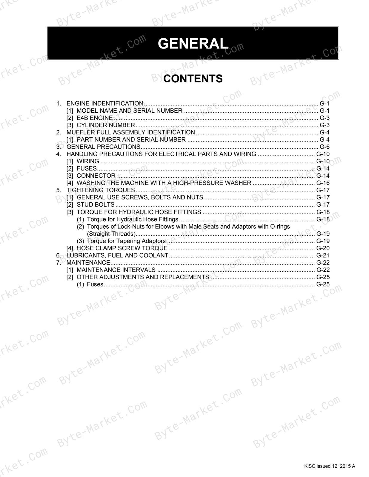
- GENERAL — p. 20
- 1. ENGINE INDENTIFICATION — p. 21
- [1] MODEL NAME AND SERIAL NUMBER — p. 21
- [2] E4B ENGINE — p. 23
- [3] CYLINDER NUMBER — p. 23
- 2. MUFFLER FULL ASSEMBLY IDENTIFICATION — p. 24
- [1] PART NUMBER AND SERIAL NUMBER — p. 24
- 3. GENERAL PRECAUTIONS — p. 26
- 4. HANDLING PRECAUTIONS FOR ELECTRICAL PARTS AND WIRING — p. 30
- [1] WIRING — p. 30
- [2] FUSES — p. 34
- [3] CONNECTOR — p. 34
- [4] WASHING THE MACHINE WITH A HIGH-PRESSURE WASHER — p. 36
- 5. TIGHTENING TORQUES — p. 37
- [1] GENERAL USE SCREWS, BOLTS AND NUTS — p. 37
- [2] STUD BOLTS — p. 37
- [3] TORQUE FOR HYDRAULIC HOSE FITTINGS — p. 38
- (1) Torque for Hydraulic Hose Fittings — p. 38
- (2) Torques of Lock-Nuts for Elbows with Male Seats and Adaptors with O-rings (Straight Threads) — p. 39
- (3) Torque for Tapering Adaptors — p. 39
- [4] HOSE CLAMP SCREW TORQUE — p. 40
- 6. LUBRICANTS, FUEL AND COOLANT — p. 41
- 7. MAINTENANCE — p. 42
- [1] MAINTENANCE INTERVALS — p. 42
- [2] OTHER ADJUSTMENTS AND REPLACEMENTS — p. 45
- (1) Fuses — p. 45
- 1. ENGINE INDENTIFICATION — p. 21
- GENERAL — p. 20
- 1 ENGINE — p. 49
- GENERAL — p. 50
- 1. SPECIFICATIONS — p. 51
- 2. DIMENSIONS — p. 52
- 3. PERFORMANCE CURVE — p. 53
- SERVICING — p. 54
- 1. ENGINE — p. 55
- [1] RADIATOR — p. 55
- (1) Removal and Installation — p. 55
- [2] DPF MUFFLER — p. 60
- (1) Removal and Installation — p. 60
- [3] ENGINE — p. 65
- (1) Removal and Installation — p. 65
- [1] RADIATOR — p. 55
- 1. ENGINE — p. 55
- GENERAL — p. 50
- 2 MACHINE BODY — p. 70
- SERVICING — p. 71
- 1. FRONT — p. 72
- [1] CAB TILT — p. 72
- [2] LIFT ARM STOPPER — p. 74
- [3] JACK UP — p. 76
- [4] DISASSEMBLY AND ASSEMBLY OF LIFT ARM, LINK AND LINK (CONTROL) — p. 78
- [5] INSTALL THE VACUUM PUMP — p. 81
- [6] MECHANICAL QUICK HITCH — p. 82
- [7] HYDRAULIC QUICK HITCH (OPTION) — p. 83
- (1) Removal and Installation — p. 84
- [8] FRONT PINS AND BUSHES — p. 86
- (1) Assembling — p. 88
- 2. UPPER STRUCTURE — p. 89
- [1] ROPS (CABIN) — p. 89
- (1) Removal and Installation — p. 89
- [2] WINDSHIELD — p. 93
- (1) Disassembly/Assembly — p. 93
- [3] SEAT BAR — p. 101
- [4] SEAT AND SEATBELT — p. 102
- [1] ROPS (CABIN) — p. 89
- 3. LOWER CHASSIS LAYOUT — p. 103
- [1] FUEL TANK — p. 103
- (1) Removal and Installation — p. 103
- [2] REAR HOOD — p. 104
- (1) Removal and Installation — p. 104
- [3] HYDRAULIC OIL TANK — p. 106
- (1) Removal and Installation — p. 106
- [4] AXLE SHAFT — p. 108
- (1) Components — p. 108
- (2) Disassembly/Assembly — p. 108
- (3) Special Tools — p. 112
- [5] SPROCKET — p. 113
- (1) Removal and Installation — p. 113
- [1] FUEL TANK — p. 103
- 1. FRONT — p. 72
- SERVICING — p. 71
- 3 HYDRAULIC SYSTEM — p. 118
- MECHANISM — p. 119
- 1. HYDRAULIC CIRCUIT DIAGRAM — p. 120
- [1] HYDRAULIC HITCH + HIGH-FLOW + SELF LEVELING VALVE + RIDE CONTROL SPEC. — p. 120
- [2] MECHANICAL QUICK HITCH SPEC. — p. 122
- [3] MECHANICAL QUICK HITCH + HIGH-FLOW SPEC. — p. 124
- [4] MECHANICAL QUICK HITCH + SELF LEVELING VALVE + RIDE CONTROL SPEC. — p. 126
- [5] MECHANICAL QUICK HITCH + HIGH-FLOW + SELF LEVELING VALVE + RIDE CONTROL SPEC. — p. 128
- [6] HYDRAULIC HITCH SPEC. — p. 130
- [7] HYDRAULIC HITCH + HIGH-FLOW SPEC. — p. 132
- [8] HYDRAULIC HITCH + SELF LEVELING VALVE + RIDE CONTROL SPEC. — p. 134
- 2. HYDRAULIC EQUIPMENT LAYOUT — p. 136
- 3. HYDRAULIC SYSTEM — p. 137
- [1] OVERVIEW — p. 137
- [2] FRONT OPERATION SYSTEM — p. 138
- (1) Overview — p. 138
- (2) Flow of Oil when in Neutral — p. 139
- (3) Raising the Lift Arm Operation — p. 140
- (4) Lift Arm Float Operation — p. 141
- (5) Bucket Dump Operation — p. 142
- (6) Lift Arm Raise + Self Leveler Switch ON Operation (without Bucket Operation) — p. 143
- (7) AUX Operation (Single Flow) — p. 144
- (8) AUX Operation (High-Flow Flow) — p. 146
- (9) Ride Control Operation — p. 148
- (10) Hydraulic Hitch Operation (when Locked) — p. 149
- [3] TRAVEL SYSTEM — p. 150
- (1) Function — p. 150
- (2) Forward Driving Operation — p. 151
- (3) Right Turn Operation (Spin Turn) — p. 152
- (4) Charge Circuit — p. 153
- (5) Flushing Circuit — p. 154
- (6) Travel High-Low Operation (Forward Driving) — p. 155
- (7) Parking Brake Operation — p. 156
- 1. HYDRAULIC CIRCUIT DIAGRAM — p. 120
- SERVICING — p. 157
- 1. SERVICE DATA — p. 159
- 2. PERFORMANCE CHECKS AND ADJUSTMENT METHODS — p. 161
- 3. HYDRAULIC EQUIPMENT — p. 171
- [1] HST PUMP — p. 171
- (1) Specifications — p. 171
- (2) Components — p. 172
- (3) Joints Arrangement — p. 174
- (4) Assembly — p. 178
- (5) Pump Coupling — p. 179
- (6) Removal and Installation — p. 180
- (7) Disassembly/Assembly — p. 182
- (8) Special Tools — p. 194
- (9) Neutral Adjustment — p. 196
- (10) Backup Buzzer Adjustment — p. 197
- [2] GEAR PUMP — p. 198
- (1) Specifications — p. 198
- (2) Components — p. 198
- (3) Joints Arrangement — p. 199
- [3] GEAR PUMP (HIGH-FLOW VERSION OPTION) — p. 200
- (1) Specifications — p. 200
- (2) Components — p. 201
- (3) Joints Arrangement — p. 202
- [4] CONTROL VALVE — p. 203
- (1) Specifications — p. 203
- (2) Joints Arrangement — p. 204
- (3) Assembly — p. 205
- (4) Removal and Installation — p. 208
- (5) Disassembly/Assembly — p. 210
- [5] TRAVEL MOTOR — p. 215
- (1) Specifications — p. 215
- (2) Components — p. 216
- (3) Joints Arrangement — p. 218
- (4) Removal and Installation — p. 220
- (5) Disassembly/Assembly — p. 221
- (6) Special Tools — p. 235
- [6] FAN MOTOR — p. 237
- (1) Specifications — p. 237
- (2) Components — p. 238
- (3) Joints Arrangement — p. 239
- (4) Removal and Installation — p. 240
- (5) Disassembly/Assembly — p. 241
- [7] LIFT ARM CYLINDER — p. 245
- (1) Specifications — p. 245
- (2) Components — p. 245
- (3) Removal and Installation — p. 246
- (4) Disassembly/Assembly — p. 248
- (5) Special Tools — p. 254
- [8] BUCKET CYLINDER — p. 258
- (1) Specifications — p. 258
- (2) Components — p. 258
- (3) Removal and Installation — p. 259
- [9] HYDRAULIC QUICK HITCH CYLINDER — p. 261
- (1) Specifications — p. 261
- (2) Components — p. 261
- (3) Removal and Installation — p. 262
- [10] 3 SPOOL SOLENOID VALVE — p. 263
- (1) Specifications — p. 263
- (2) Components — p. 264
- (3) Joints Arrangement — p. 265
- [11] QUICK HITCH SOLENOID VALVE (OPTION) — p. 266
- (1) Specifications — p. 266
- (2) Components — p. 267
- (3) Joints Arrangement — p. 268
- [12] HIGH-FLOW SOLENOID VALVE (OPTION) — p. 269
- (1) Specifications — p. 269
- (2) Joints Arrangement — p. 270
- (3) Disassembly/Assembly — p. 270
- [13] HORIZONTAL CONTROL VALVE (OPTION) — p. 272
- (1) Specifications — p. 272
- (2) Disassembly/Assembly — p. 273
- (3) Joints Arrangement — p. 275
- [14] RIDE CONTROL SOLENOID VALVE (OPTION) — p. 277
- (1) Specifications — p. 277
- (2) Components — p. 278
- (3) Accumulator Assembly — p. 279
- (4) Joints Arrangement — p. 280
- [15] BLOCK VALVE (OPTION) — p. 281
- (1) Specifications — p. 281
- (2) Components — p. 282
- (3) Joints Arrangement — p. 283
- [1] HST PUMP — p. 171
- MECHANISM — p. 119
- 4 ELECTRICAL SYSTEM — p. 284
- SERVICING — p. 285
- 1. DIAGNOSING MALFUNCTIONS — p. 288
- [1] OVERVIEW OF MALFUNCTION DIAGNOSIS — p. 288
- [2] STEPS IN DIAGNOSING MALFUNCTIONS — p. 288
- [3] TESTING WITH A CIRCUIT TESTER — p. 289
- 2. WIRING CIRCUIT — p. 291
- [1] PRECAUTIONS ON HOW TO CLAMP THE ELECTRICAL WIRING — p. 291
- [2] PRECAUTIONS ON HANDLING ELECTRICAL CONNECTORS — p. 291
- 3. ELECTRONIC EQUIPMENT LAYOUT — p. 292
- 4. ELECTRICAL CONNECTOR LAYOUT — p. 293
- [1] ROPS/CAB, A/C SPECIFICATION — p. 293
- 5. TERMINAL NAMES OF THE MAIN CONNECTOR — p. 327
- 6. INSTRUMENT PANEL — p. 328
- [1] PANEL FUNCTIONS — p. 328
- (1) Lamp Displays — p. 328
- (2) Warning Lamp — p. 328
- (3) Alarm — p. 328
- [2] USER MODE — p. 329
- [3] SERVICE MODE — p. 334
- (1) What is the Service Mode? — p. 334
- (2) Entering the Service Mode — p. 335
- (3) Using the Service Modes — p. 337
- [1] PANEL FUNCTIONS — p. 328
- 7. TROUBLESHOOTING — p. 348
- [1] No.3 HYDRAULIC OIL TEMPERATURE SENSOR ERRORS (E:005) — p. 348
- (1) Checking via the Panel Display — p. 348
- (2) Inspecting each Device Visually and Physically — p. 348
- (3) Testing with a Circuit Tester — p. 350
- (4) Testing the Equipment Itself — p. 351
- [2] No.4 FUEL SENSOR SYSTEM ERRORS (E:008) — p. 352
- (1) Checking via the Panel Display — p. 352
- (2) Inspecting each Device Visually and Physically — p. 353
- (3) Testing with a Circuit Tester — p. 354
- (4) Testing the Equipment Itself — p. 355
- [3] No.5 ACCELERATION SYSTEM ERRORS (E:009) — p. 356
- (1) Checking via the Panel Display — p. 356
- (2) Inspecting each Device Visually and Physically — p. 356
- (3) Testing with a Circuit Tester — p. 358
- (4) Testing the Equipment Itself — p. 360
- [4] No.6 TWO-SPEED TRAVEL SOLENOID ERROR (E:010) — p. 361
- (1) Checking via the Panel Display — p. 361
- (2) Inspecting each Device Visually and Physically — p. 362
- (3) Testing with a Circuit Tester — p. 363
- (4) Testing the Equipment Itself — p. 364
- [5] No.7 PARKING BRAKE SOLENOID ERRORS (E:011) — p. 366
- (1) Checking via the Panel Display — p. 366
- (2) Inspecting each Device Visually and Physically — p. 367
- (3) Testing with a Circuit Tester — p. 369
- (4) Testing the Equipment Itself — p. 370
- [6] No.8 HIGH-FLOW SOLENOID ERRORS (E:014) — p. 372
- (1) Checking via the Panel Display — p. 372
- (2) Inspecting each Device Visually and Physically — p. 374
- (3) Testing with a Circuit Tester — p. 375
- (4) Testing the Equipment Itself — p. 376
- [7] No.9 HYDRAULIC QUICK-HITCH LOCK SOLENOID (E:015) — p. 379
- (1) Checking via the Panel Display — p. 379
- (2) Inspecting each Device Visually and Physically — p. 380
- (3) Testing with a Circuit Tester — p. 381
- (4) Testing the Equipment Itself — p. 382
- [8] No.10 AUX KNOB ERRORS (E:016) — p. 384
- (1) Checking via the LCD Panel Display — p. 384
- (2) Inspecting each Device Visually and Physically — p. 385
- (3) Testing with a Circuit Tester — p. 386
- (4) Testing the Equipment Itself — p. 387
- [9] No.11 AUX RIGHT SOLENOID ERRORS (E:018) — p. 389
- (1) Checking via the LCD Panel Display — p. 389
- (2) Inspecting each Device Visually and Physically — p. 391
- (3) Testing with a Circuit Tester — p. 392
- (4) Testing the Equipment Itself — p. 393
- [10] No.12 AUX LEFT SOLENOID ERRORS (E:019) — p. 395
- (1) Checking via the LCD Panel Display — p. 395
- (2) Inspecting each Device Visually and Physically — p. 397
- (3) Testing with a Circuit Tester — p. 398
- (4) Testing the Equipment Itself — p. 399
- [11] No.13 5V SHORT SYSTEM ERRORS (E:021) — p. 401
- (1) Checking via the Panel Display — p. 401
- (2) Inspecting each Device Visually and Physically — p. 402
- (3) Testing the Equipment Itself — p. 403
- [12] No.14 OVER VOLTAGE ERRORS (E:023) — p. 404
- (1) Checking via the Panel Display — p. 404
- (2) Testing with a Circuit Tester — p. 404
- [13] No.16 CRS COMMUNICATION ERRORS (E:026) — p. 405
- (1) Checking via the Panel Display — p. 405
- (2) Inspecting each Device Visually and Physically — p. 405
- (3) Testing with a Circuit Tester — p. 405
- (4) Testing the Equipment Itself — p. 406
- [14] No.17 RIDE CONTROL SOLENOID ERRORS (E:027) — p. 407
- (1) Checking via the Panel Display — p. 407
- (2) Inspecting each Device Visually and Physically — p. 408
- (3) Testing with a Circuit Tester — p. 410
- (4) Testing the Equipment Itself — p. 411
- [15] No.18 FAN SOLENOID ERRORS (E:028) — p. 413
- (1) Checking via the Panel Display — p. 413
- (2) Inspecting each Device Visually and Physically — p. 413
- (3) Testing with a Circuit Tester — p. 414
- (4) Testing the Equipment Itself — p. 415
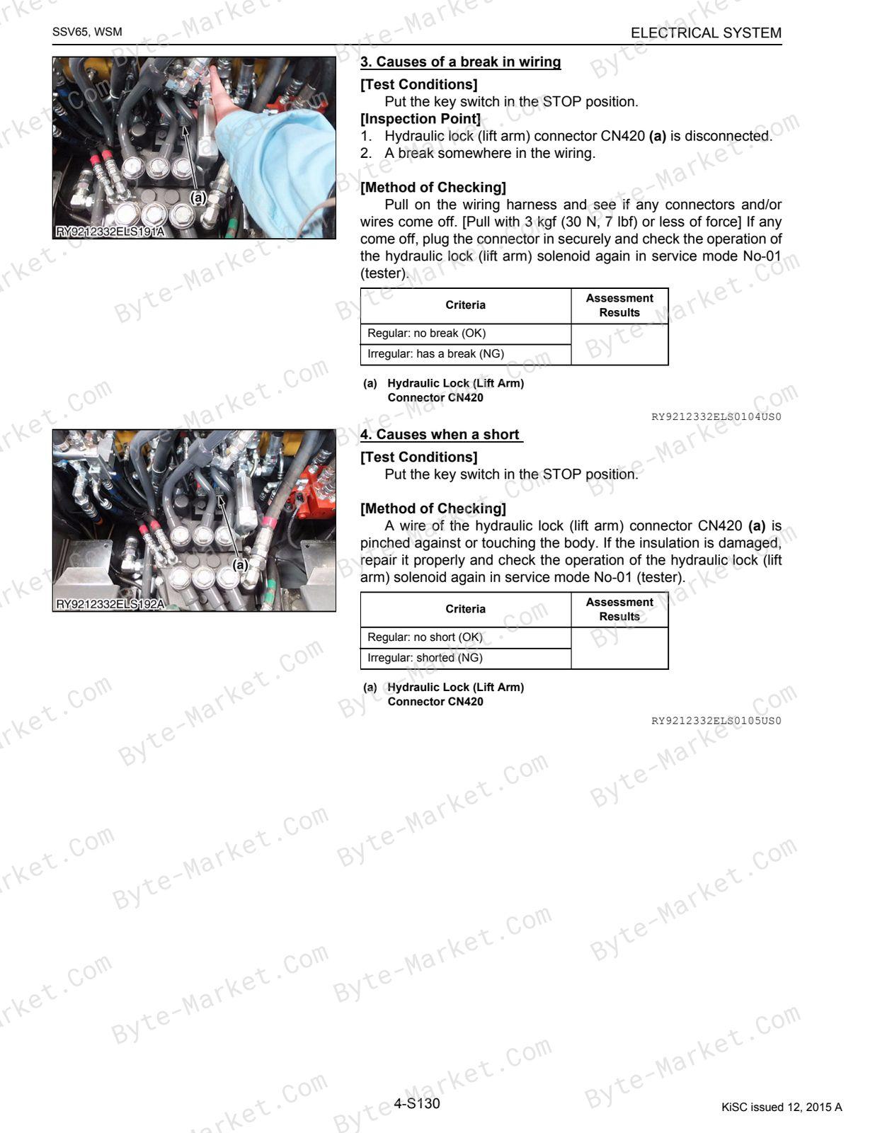
- [16] No.19 HYDRAULIC LOCK (LIFT ARM) ERRORS (E:029) — p. 416
- (1) Checking via the Panel Display — p. 416
- (2) Inspecting each Device Visually and Physically — p. 416
- (3) Testing with a Circuit Tester — p. 418
- (4) Testing the Equipment Itself — p. 418
- [17] No.20 HYDRAULIC LOCK (BUCKET) ERRORS (E:030) — p. 420
- (1) Checking via the Panel Display — p. 420
- (2) Inspecting each Device Visually and Physically — p. 420
- (3) Testing with a Circuit Tester — p. 422
- (4) Testing the Equipment Itself — p. 422
- [18] No.21 TRAVEL PILOT PRESSURE SENSOR ERRORS (E:031) — p. 424
- (1) Checking via the Panel Display — p. 424
- (2) Inspecting each Device Visually and Physically — p. 425
- (3) Testing with a Circuit Tester — p. 426
- (4) Testing the Equipment Itself — p. 427
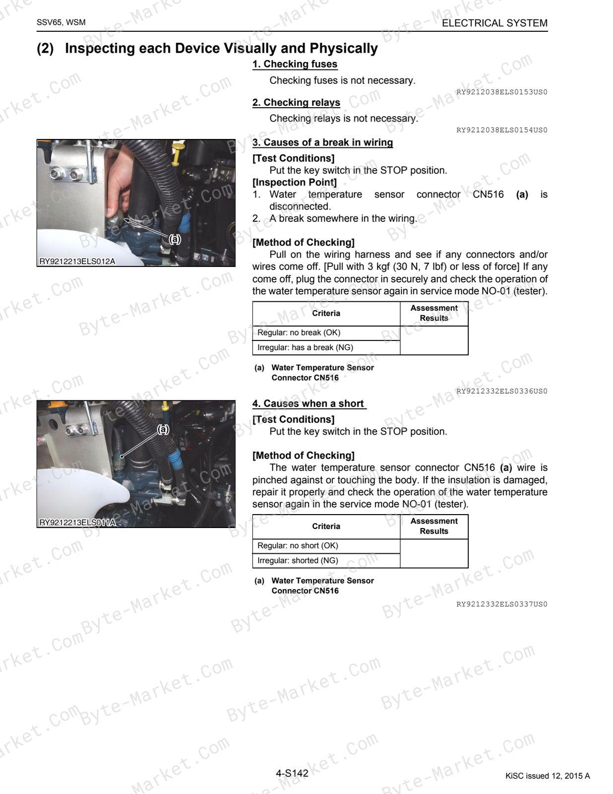
- [19] No.29 WATER TEMPERATURE SENSOR OVERHEATING ERRORS (E:9104) — p. 428
- (1) Checking via the Panel Display — p. 428
- (2) Inspecting each Device Visually and Physically — p. 429
- (3) Testing with a Circuit Tester — p. 430
- (4) Testing the Equipment Itself — p. 431
- [20] No.47 ENGINE OIL PRESSURE ERRORS (E:9118) — p. 432
- (1) Checking via the Panel Display — p. 432
- (2) Inspecting each Device Visually and Physically — p. 432
- (3) Testing with a Circuit Tester — p. 433
- (4) Testing the Equipment Itself — p. 435
- [21] No.48 CHARGE ERRORS (E:9119) — p. 436
- (1) Checking via the Panel Display — p. 436
- (2) Inspecting each Device Visually and Physically — p. 436
- (3) Testing with a Circuit Tester — p. 437
- [22] No.49 WATER SEPARATOR, WATER FULL ERRORS (E:9120) — p. 439
- (1) Checking via the Panel Display — p. 439
- (2) Inspecting each Device Visually and Physically — p. 439
- [1] No.3 HYDRAULIC OIL TEMPERATURE SENSOR ERRORS (E:005) — p. 348
- 7. FLOW CHART OF THE USER MODE AND SERVICE MODE SETTINGS — p. 440
- 1. DIAGNOSING MALFUNCTIONS — p. 288
- SERVICING — p. 285
- 5 CABIN — p. 442
- MECHANISM — p. 443
- 1. AIR CONDITIONING SYSTEM — p. 444
- [1] STRUCTURE — p. 444
- [2] HOW THE MECHANISMS OF THE SYSTEM WORK — p. 446
- [3] COMPRESSOR — p. 447
- [4] AIR CONDITIONING UNIT — p. 450
- [5] CONDENSER — p. 455
- [6] RECEIVER — p. 456
- [7] PRESSURE SWITCH — p. 457
- [8] SYSTEM CONTROLS — p. 458
- [9] ADJUSTING THE AIR FLOW AND DIRECTION — p. 459
- [10] ELECTRICAL SYSTEM — p. 460
- (1) Electrical Circuits — p. 460
- (2) Relays — p. 461
- 2. WIPER — p. 462
- [1] WIPER SWITCH — p. 462
- [2] WIPER MOTOR — p. 462
- 1. AIR CONDITIONING SYSTEM — p. 444
- SERVICING — p. 463
- 1. TROUBLESHOOTING — p. 464
- 2. MAINTENANCE AND SERVICE RELATED SPECIFICATIONS — p. 467
- 3. PRECAUTIONS WHEN REPAIRING THE REFRIGERANT SYSTEM — p. 468
- [1] USE OF SERVICE TOOLS — p. 468
- (1) Manifold Gauge Set — p. 468
- (2) Refrigerant Charging Hoses — p. 470
- (3) Vacuum Pump Adapter — p. 471
- (4) Electric Gas Leak Tester — p. 471
- (5) Canister Tap Valve — p. 471
- (6) T-Joint — p. 472
- (7) R134a Refrigerant Collection/Recycling Device — p. 472
- [1] USE OF SERVICE TOOLS — p. 468
- 4. INSPECTING AND CHARGING THE REFRIGERANT SYSTEM — p. 473
- [1] CHECKING THE SYSTEM WITH A MANIFOLD GAUGE — p. 473
- [2] COLLECTION, VACUUMING AND CHARGING — p. 478
- (1) Collecting Refrigerant — p. 478
- (2) Vacuuming Out the System — p. 479
- [3] CHARGING FROM THE HIGH-PRESSURE SIDE — p. 480
- [4] CHARGING FROM THE LOW-PRESSURE SIDE — p. 481
- 5. INSPECTION AND DISASSEMBLY — p. 482
- [1] CHECKS AND ADJUSTMENTS — p. 482
- (1) Compressor — p. 482
- (2) Relays — p. 484
- (3) Blower Motor — p. 486
- (4) Blower Resistor — p. 487
- (5) A/C Switch — p. 487
- (6) Fan Switch — p. 488
- (7) Pressure Switch — p. 489
- [2] DISASSEMBLY AND ASSEMBLY — p. 491
- (1) Removal and Installation of the A/C Unit — p. 491
- (2) Mounting and Removing the Compressor — p. 492
- (3) Connecting/Disconnecting A/C Hoses — p. 495
- (4) Removal and Installation of Heater Hoses — p. 498
- (5) Heater Hose Routing — p. 500
- [1] CHECKS AND ADJUSTMENTS — p. 482
- MECHANISM — p. 443
- Electrical Circuit Diagram — p. 501
Capabilities
The source outline separates mechanism explanations from servicing instructions for Hydraulic System and Cabin. Use these indexed headings to locate the applicable system in the source PDF, then confirm model-specific notes, specifications, illustrations, and operating conditions at the relevant page before carrying out service work.
Keep the source's safety sequence, prerequisite steps, labels, units, configuration notes, and footnotes with the selected task; do not apply an isolated value outside the conditions stated in the manual.
Technical reference
Reference tables include torque settings, fluid and system capacities, and emission data for service checks, adjustment work, and specification lookup. Use the values and conditions in the PDF for the applicable model and procedure.
- Service limits and settings: torque settings.
- Fluid reference: fluid and system capacities.
- Electrical and emissions: emission data.
Delivery
This manual is supplied as a digital PDF file and is available for instant download after purchase. No physical media is shipped.
References
Kubota Workshop Manual for Skid Steer Loader, document code RY911-23332, PDF edition.


No questions found.