
Kubota Workshop Manual
Kubota U20-3, U25-3, and U25S Excavator Workshop Manual
Document number 97899-61490 · English PDF edition · 162 pages
About this manual
Kubota published this Workshop Manual for the U20-3, U25-3, and U25S excavator models. It brings the documented service and technical-reference material for those named excavators into a single publication.
The manual is especially useful for work that crosses electrical and hydraulic systems: it includes electrical troubleshooting, alongside hydraulic diagrams.
Use the Manual Contents below to check that the exact repair, inspection, or maintenance procedure you need is included in this publication.
Manual details
- Manufacturer
- Kubota
- Manual type
- Workshop Manual, Mechanism Chapter
- Equipment type
- Excavator
- Models
- U20-3, U25-3, and U25S
- Document number
- 97899-61490
- Language
- English
- Page count
- 162
Product highlights
Electrical systems
The manual includes wiring diagrams and electrical troubleshooting.
Hydraulic systems
The manual includes hydraulic circuit diagrams.
Applicability and key coverage
Named models: U20-3, U25-3, and U25S.
Manual contents
Use these source headings to locate the task or system you need in the PDF.
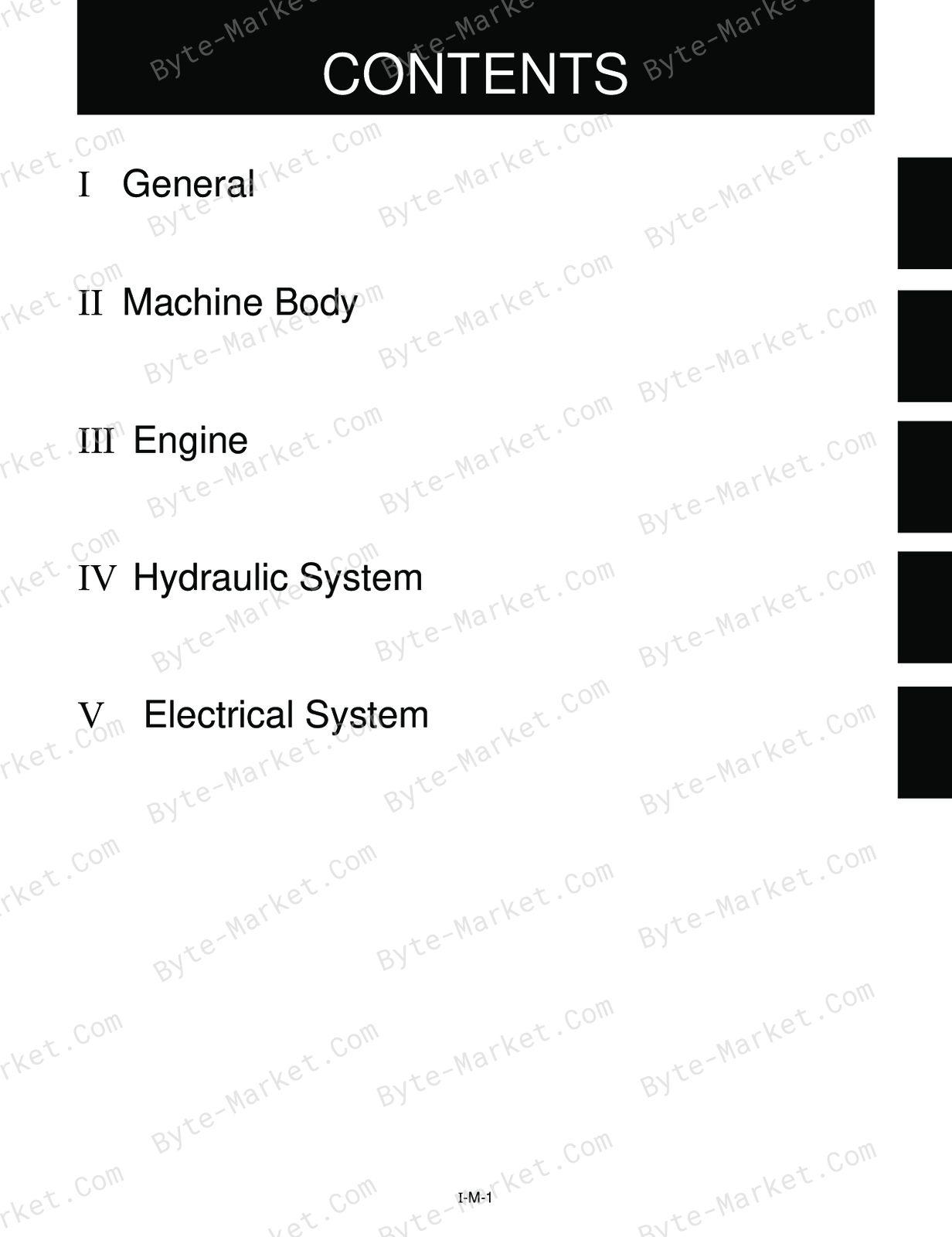
- WSM U25S U20-3a/25-3a — p. 1
- I General — p. 5
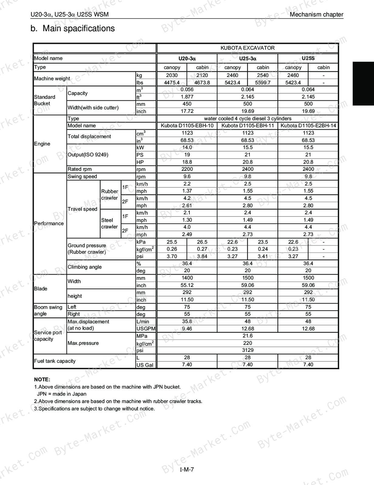
- A. Features and specifications — p. 7
- a. Feature quick chart — p. 7
- b. Main spacifications — p. 9
- c. Comparison of spacifications for U25S — p. 10
- d. Major components comparision — p. 11
- B. U25S ; PP-version featured points — p. 12
- C. U20-3a/U25-3a ; EU-version featured points — p. 18
- D. Machine Quality Specifications — p. 26
- A. Features and specifications — p. 7
- III Engine — p. 33
- A. Engine Specifications for construction machinery — p. 35
- Performance curves (Machine model : U20-3a, EU-version) — p. 37
- Performance curves (Machine model : U25-3a, EU-version) — p. 38
- Performance curves (Machine model : U25S, PP-version) — p. 39
- A. Engine Specifications for construction machinery — p. 35
- IV. Hydraulic system — p. 41
- A. Features of hydraulic system — p. 43
- B. Hydraulic system specifications — p. 44
- C. Main pump — p. 46
- a. Structure & specifications — p. 46
- b. Performance curve — p. 47
- c. Operating principle — p. 49
- D. Control valve — p. 50
- a. Specifications — p. 50
- b. General view of control valve — p. 51
- c. Sectional view — p. 53
- d. Arm regeneration circuit — p. 58
- e. Boom anti-fall valve — p. 59
- (1) At neutral position of boom section — p. 59
- (2) Boom up (with port Pa under pressure) — p. 60
- (3) Boom down (with port Pb under pressure) — p. 62
- f. Straight travel circuit — p. 64
- g. Simultaneous operation of boom & bucket — p. 65
- h. Relief valve/Anti-cavitation valve — p. 66
- i. Automatic air bleeding in hydraulic pilot section — p. 67
- E. Pilot valve — p. 68
- a. Structure — p. 68
- b. Pilot valve control diagram — p. 70
- c. Function — p. 71
- F. Swivel motor — p. 74
- a. Structure & specifications — p. 74
- b. Operating principle — p. 75
- c. Function of negative brake — p. 77
- G. Rotary joint (Swivel joint) — p. 78
- Fixed undercarriage (U20-3a, U25-3a, U25S) — p. 78
- Retractable undercarriage (U20-3a) — p. 78
- Fixed undercarriage (U20-3, U25-3a, U25S) — p. 79
- Retractable undercarriage (U20-3a,) — p. 79
- H. Travel motor — p. 80
- a. Travel motor Specifications — p. 80
- b. U20-3a (Fujikoshi) — p. 81
- 1.Structure, U20-3a (Fujikoshi) — p. 81
- 2. Principle of operation — p. 82
- (1) Operating principle of wheel motor — p. 82
- (2) Reducer — p. 83
- (3) Hydraulic motor — p. 84
- (4) Hydraulic valve (counter balance valve) — p. 86
- c. U25-3a, U25S (Kayaba) — p. 87
- Structure, U25-3a, U25S (Kayaba) — p. 87
- Operating principle of motor — p. 88
- Operating principle of counter valance valve — p. 89
- Counter balance function — p. 90
- Brake function — p. 91
- Function of Hi-Lo change — p. 92
- 1)1st (low) speed — p. 92
- 2) 2nd (high) speed — p. 93
- Function of reduction gear — p. 94
- Function of anti-cavitation valve — p. 95
- (1) Construction — p. 95
- (2) Circuit behavior — p. 96
- d. Hydraulic components layout — p. 101
- I. Hydraulic circuit diagram — p. 102
- a. U20-3a, EU-version Fixed undercarriage — p. 102
- b. U20-3a, EU-version Retractable undercarriage — p. 103
- c. U25-3a, EU-version — p. 104
- d. U25S, PP-version — p. 105
- e. U20-3a, EU-version, travel straight and boom-up — p. 106
- V. Electrical system — p. 107
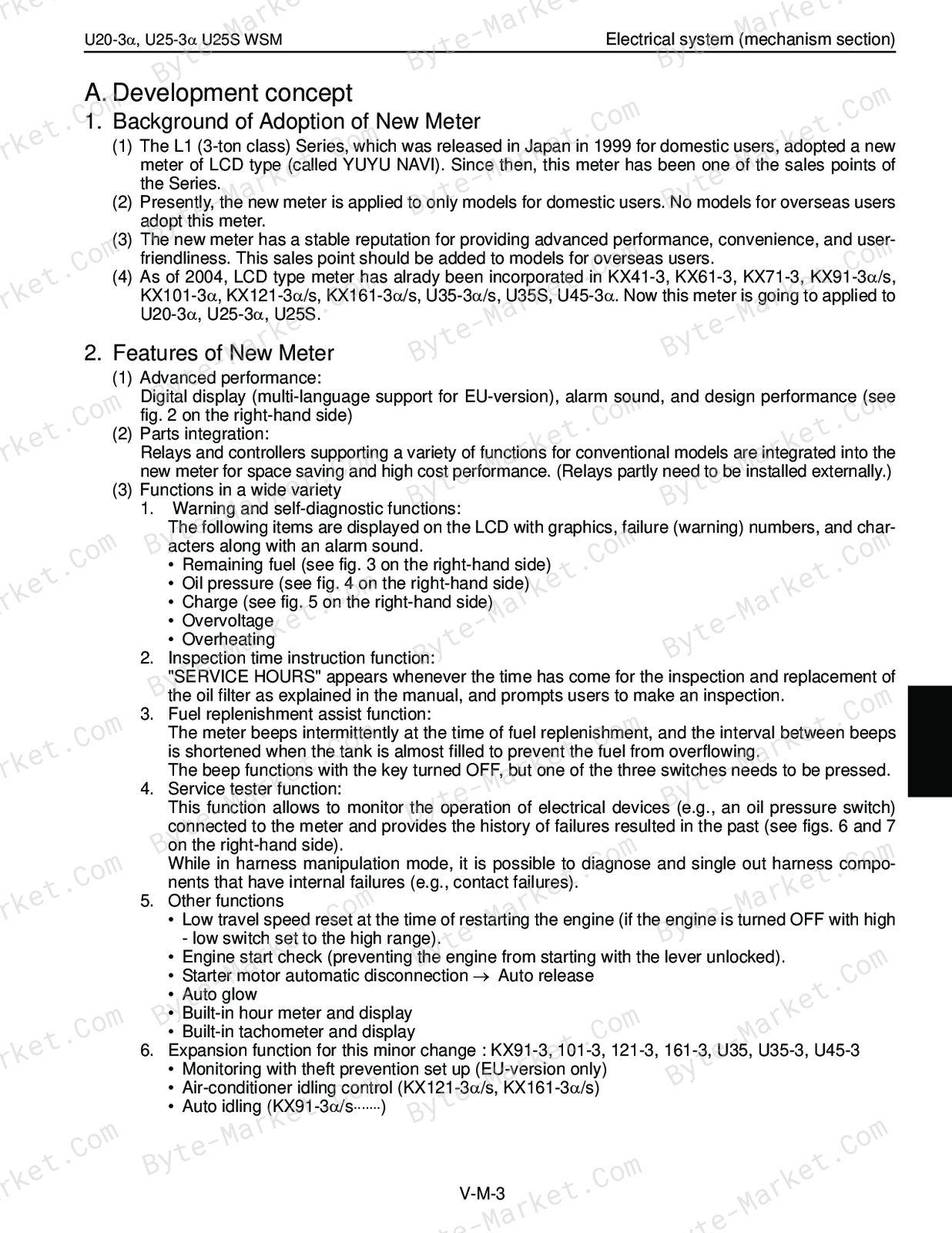
- A. Development concept — p. 109
- 1. Background of Adoption of New Meter — p. 109
- 2. Features of New Meter — p. 109
- 3. Electrical system : Functional comparison — p. 111
- B. Outline of Kubota ICS (Intelligent Control System) — p. 112
- C. Operating Mode — p. 115
- 1. Outline — p. 115
- 2. LCD display list — p. 116
- D. Service mode menues — p. 118
- 1. Outline — p. 118
- 2. Service mode flow chart — p. 118
- 3. Main menues and functions — p. 119
- E. Main component’s function — p. 138
- (1) Auto release function — p. 138
- (2) Travel hi-speed control circuit — p. 143
- (3) Meter panel (Controller unit) — p. 144
- (4) Engine speed sensor — p. 145
- (5) Governor sensor — p. 146
- F. Failure Diagnosis — p. 147
- 1. Failure display and diagnosis criteria — p. 147
- 2. Fail record in EEPROM — p. 149
- G. Service mode flow chart — p. 153
- 1. General — p. 153
- H. Layout, flow chart and diagram — p. 155
- 1. Electrical componet layout — p. 155
- 2. Service mode U20-3a, U25-3a, U25S — p. 156
- 3. Electrical wiring diagram : U20-3a, U25-3a, U25-S — p. 157
- Conversion Tables — p. 159
- A. Development concept — p. 109
- I General — p. 5
Capabilities
The source outline indexes servicing instructions. Use these source-backed headings to locate the applicable task or system in the source PDF, then confirm model-specific notes, specifications, illustrations, and operating conditions at the relevant page before carrying out service work.
Keep the source's safety sequence, prerequisite steps, labels, units, configuration notes, and footnotes with the selected task; do not apply an isolated value outside the conditions stated in the manual.
Delivery
This manual is supplied as a digital PDF file and is available for instant download after purchase. No physical media is shipped.
References
Kubota Workshop Manual for Excavator, document code 97899-61490, PDF edition.


No questions found.