
New Holland Service Manual
New Holland Boomer 8N Service Manual
Document number 84307374 · English PDF edition · 947 pages
About this manual
New Holland published this Service Manual for Boomer 8N. It provides documented maintenance, service, and repair material for that equipment.
Its Engine section includes Torque Specification, Metric Bolt Torque Specifications, Compression Test and Tools, Troubleshooting, Cylinder Head and Valve Train Components, Overhaul - Engine, and Fuel Injector and Glow Plug.
Use the Manual Contents below to check that the exact maintenance, inspection, service, or repair procedure you need is included in this publication.
Manual details
- Manufacturer
- New Holland
- Manual type
- Service Manual
- Models
- Boomer 8N
- Document number
- 84307374
- Publication relationship
- Supersedes 84218897
- Publication year
- 2010
- Publication date
- 6/10
- Language
- English
- Page count
- 947
Product highlights
Electrical systems
The manual includes wiring diagrams, electrical troubleshooting, and pinouts.
Hydraulic systems
The manual includes hydraulic circuit diagrams, hydraulic pressure-test material, and hydraulic valve-adjustment material.
Specifications and settings
The manual includes reference information for wear limits and torque specifications.
Special tools
A special-tools section is included.
Maintenance
The manual includes a maintenance schedule.
Manual contents
Use these source headings to locate the task or system you need in the PDF.
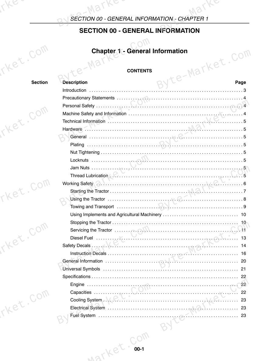
- Introduction — p. 3
- Precautionary Statements — p. 4
- Personal Safety — p. 4
- Machine Safety and Information — p. 4
- Technical Information — p. 5
- Hardware — p. 5
- General — p. 5
- Plating — p. 5
- Nut Tightening — p. 5
- Locknuts — p. 5
- Jam Nuts — p. 5
- Thread Lubrication — p. 5
- Working Safety — p. 6
- Starting the Tractor — p. 7
- Using the Tractor — p. 8
- Towing and Transport — p. 9
- Using Implements and Agricultural Machinery — p. 10
- Stopping the Tractor — p. 10
- Servicing the Tractor — p. 11
- Diesel Fuel — p. 13
- Safety Decals — p. 14
- Instruction Decals — p. 16
- General Information — p. 20
- Universal Symbols — p. 21
- Specifications — p. 22
- Engine — p. 22
- Capacities — p. 22
- Cooling System — p. 23
- Electrical System — p. 23
- Fuel System — p. 23
- Brakes — p. 24
- Steering — p. 24
- Power Take-off — p. 24
- Hydraulic Lift System — p. 24
- Transmission — p. 25
- Transmission Speeds - km/h (mph) — p. 25
- Cast Iron Weights — p. 26
- Drawbars — p. 26
- 3 Point Hitch — p. 26
- Tires — p. 27
- Wheel Bolt Torques — p. 27
- General Dimensions — p. 28
- Minimum Hardware Tightening Torques — p. 32
- Special Tools — p. 34
- Tire Ballast and Pressures — p. 36
- Liquid Ballast (Optional) — p. 36
- Tire Pressure — p. 36
- Rear Tire Liquid — p. 36
- Specifications — p. 6
- General — p. 6
- Cylinder Block — p. 6
- Cylinder Head — p. 7
- Piston — p. 7
- Piston Pin — p. 8
- Piston Ring — p. 8
- Connecting Rod — p. 9
- Crankshaft — p. 9
- Camshaft — p. 10
- Valves — p. 10
- Push Rods — p. 11
- Rocker Arm — p. 11
- Lubrication System — p. 11
- Cooling System — p. 12
- Torque Specification — p. 12
- Metric Bolt Torque Specifications — p. 13
- Special Tools — p. 14
- Compression Test and Tools — p. 15
- Description of Operation — p. 16
- Troubleshooting — p. 17
- Cylinder Head and Valve Train Components — p. 21
- Separating the Tractor at the Engine - Front Transmission Box — p. 22
- Removal — p. 22
- Separating the Tractor at the Engine/Frame — p. 25
- Installation — p. 27
- Attaching the Front Transmission Box to the Engine — p. 31
- Overhaul - Engine — p. 35
- Fuel Injector and Glow Plug — p. 35
- Removal — p. 35
- Oil Pressure Switch — p. 35
- Fuel Injector and Glow Plug — p. 35
- Temperature Sending Switch and Alternator — p. 35
- Removal — p. 35
- Fan, Water Pump, and External Oil Tube — p. 36
- Removal — p. 36
- Air Inlet Manifold — p. 36
- Removal — p. 36
- Rocker Arm Shaft and Support Bracket — p. 37
- Removal — p. 37
- Cylinder Head — p. 37
- Removal — p. 37
- Valve Tappet — p. 37
- Removal — p. 37
- Fuel Shutoff Solenoid — p. 38
- Removal — p. 38
- Engine Timing Gear Cover, Timing Gears, and Cam Shaft — p. 38
- Timing Gear Cover Removal — p. 38
- Timing Gears and Camshaft — p. 40
- Removal — p. 40
- Oil Sump — p. 41
- Removal — p. 41
- Oil Suction Pipe and Strainer — p. 41
- Removal — p. 41
- Balancer Assembly — p. 42
- Removal — p. 42
- Connecting Rods, Bearings, and Pistons, Rings — p. 42
- Removal — p. 42
- Flywheel — p. 43
- Removal — p. 43
- Backplate and Oil Seal — p. 43
- Removal — p. 43
- Crankshaft and Main Bearings — p. 43
- Removal — p. 43
- Cylinder Head — p. 44
- Disassembly — p. 44
- Inspection and Repair — p. 44
- Valve Seats — p. 45
- Valves — p. 46
- Valve Guides — p. 47
- Valve Springs — p. 48
- Rocker Arms — p. 48
- Push Rods — p. 49
- Cylinder Head — p. 49
- Assembly — p. 49
- Cylinder Block — p. 50
- Pistons — p. 50
- Disassembly and Inspection — p. 50
- Piston Rings — p. 53
- Connecting Rods — p. 53
- Pin to Bushing Clearance — p. 54
- Connecting Rod Bearing — p. 55
- Clearance Check — p. 55
- Pistons, Rings, and Connecting Rod — p. 56
- Assembly — p. 56
- Crankshaft - Main Bearing and Thrust Washer — p. 57
- Removal and Inspection — p. 57
- Crankshaft — p. 58
- Bearing (Bushing) — p. 59
- Replacement — p. 59
- Main Bearing — p. 60
- Assembly — p. 60
- Port Block — p. 61
- Removal — p. 61
- Installation — p. 61
- Timing Gear — p. 62
- Camshaft — p. 62
- Disassembly — p. 62
- Inspection — p. 62
- Assembly — p. 63
- Flywheel — p. 63
- Timing Gear Housing — p. 64
- Front Oil Seal and Steering Pump Seal — p. 64
- Replacement — p. 64
- Crankshaft and Bearing Holder — p. 65
- Installation — p. 65
- Rear Oil Seal and Backplate — p. 65
- Installation — p. 65
- Flywheel — p. 66
- Installation — p. 66
- Pistons and Connecting Rods — p. 66
- Installation — p. 66
- Balancer Assembly — p. 67
- Installation — p. 67
- Balancer Shims — p. 67
- Oil Suction Pipe and Suction Strainer — p. 68
- Installation — p. 68
- Oil Sump — p. 68
- Installation — p. 68
- Camshaft and Camshaft Gear — p. 68
- Installation — p. 68
- Idler Gear, Oil Pump, and Injection Timing — p. 69
- Installation — p. 69
- Timing Gear Cover — p. 69
- Installation — p. 69
- Crankshaft Pulley — p. 69
- Installation — p. 69
- Fuel Injection Pump — p. 70
- Installation — p. 70
- Hydraulic Oil Pump — p. 70
- Installation — p. 70
- Power Steering Pump — p. 71
- Installation — p. 71
- Head Gasket Selection — p. 71
- Selection Chart — p. 71
- Cylinder Head — p. 72
- Installation — p. 72
- Valve Clearance — p. 72
- Adjustment — p. 72
- Valve Cover — p. 73
- Installation — p. 73
- Water Pump and Cooling Fan — p. 73
- Installation — p. 73
- External Oil Tube — p. 73
- Assembly — p. 73
- Glow Plug and Connector — p. 74
- Installation — p. 74
- Fuel Injector — p. 74
- Installation — p. 74
- Fuel Piping — p. 74
- Installation — p. 74
- Alternator and Temperature Sender Switch — p. 75
- Installation — p. 75
- Exhaust Manifold — p. 75
- Installation — p. 75
- Description of Operation - Engine Lubrication System — p. 76
- Oil Filter — p. 79
- Construction and Function — p. 79
- Maintenance — p. 79
- Oil Pump — p. 79
- Removal — p. 79
- Inspection — p. 79
- Installation and Adjustment — p. 80
- Engine Oil Pressure — p. 81
- Check — p. 81
- Oil Pressure Relief Valve — p. 82
- Removal — p. 82
- Installation — p. 82
- Oil Consumption — p. 82
- Oil Filter — p. 79
- Description of Operation - Cooling System — p. 83
- Maintenance — p. 85
- Coolant — p. 85
- Radiator Cap — p. 85
- Thermostat — p. 86
- Water Pump — p. 86
- Cooling Fan — p. 86
- Overhaul - Cooling System — p. 87
- Radiator — p. 87
- Removal — p. 87
- Inspection and Repair — p. 88
- Installation — p. 88
- Water Pump — p. 89
- Removal — p. 89
- Inspection and Repair — p. 91
- Installation — p. 91
- Thermostat — p. 92
- Removal — p. 92
- Inspection and Repair — p. 92
- Installation — p. 93
- Radiator — p. 87
- Front Transmission Box — p. 2
- Separating the Front Transmission Box from the Differential Housing — p. 2
- Installing the Front Transmission Box to the Differential Housing — p. 4
- Front Transmission Box — p. 7
- Disassembly — p. 7
- Assembly — p. 13
- Forward/Reverse Shuttle Clutch — p. 20
- Disassembly — p. 20
- Assembly — p. 23
- Forward Clutch Calibration — p. 26
- Reverse Clutch Calibration — p. 29
- Bolt Torque Specifications — p. 3
- Metric Bolt Torque Specifications — p. 4
- Special Tools — p. 5
- Description of Operation — p. 6
- Variator — p. 7
- PIV (ARON) Valve — p. 9
- General Operation — p. 9
- Operating Speeds — p. 10
- Overhaul — p. 18
- Variator — p. 18
- Removal — p. 18
- Inspection — p. 19
- Hydraulic Pump — p. 20
- Removal — p. 20
- Disassembly — p. 20
- Inspection — p. 21
- Assembly — p. 23
- Variator Output Speed Sensor — p. 24
- Removal — p. 24
- Testing — p. 25
- Hydraulic Oil Pressure Sensor — p. 26
- Removal — p. 26
- Testing — p. 26
- G-Rotor Pump Inner Filter — p. 27
- Removal — p. 27
- Inspection — p. 27
- Rear PTO/FWD Hydraulic Valves — p. 27
- Removal — p. 27
- Secondary Pulley Output Shaft — p. 28
- Removal — p. 28
- Inspection — p. 29
- Park Lock Control — p. 30
- Removal — p. 30
- Inspection — p. 31
- Variator — p. 18
- Primary Pulley Oil Distribution Pipe — p. 31
- Removal — p. 31
- Inspection — p. 32
- Transmission Release Control — p. 32
- Removal — p. 32
- Inspection — p. 33
- Drive Pinion — p. 34
- Removal — p. 34
- Inspection — p. 35
- Planetary Reduction Gear — p. 35
- Disassembly — p. 35
- Inspection — p. 36
- Assembly — p. 37
- Drive Pinion — p. 39
- Installation — p. 39
- Transmission Release Control — p. 39
- Installation — p. 39
- Primary Pulley Oil Distribution Pipe — p. 40
- Installation — p. 40
- Park Lock Control — p. 41
- Installation — p. 41
- Secondary Pulley Output Shaft — p. 42
- Installation — p. 42
- Rear Pto/Fwd Hydraulic Valves — p. 43
- Installation — p. 43
- G-rotor Pump Inner Filter — p. 43
- Installation — p. 43
- Hydraulic Oil Pressure Sensor — p. 44
- Installation — p. 44
- Variator Output Speed Sensor — p. 44
- Installation — p. 44
- Hydraulic Pump — p. 44
- Installation — p. 44
- Variator — p. 45
- Installation — p. 45
- Variator Calibration — p. 48
- CVT Transmission Sensors, Valves and Switches — p. 2
- Specifications — p. 3
- Front to Rear Axle Ratio — p. 3
- Boomer 8N — p. 3
- Front to Rear Axle Ratio — p. 3
- Bolt Torque Specifications — p. 6
- Special Tools — p. 6
- Description of Operation - FWD Front Axle — p. 7
- FWD Front Axle — p. 7
- Troubleshooting — p. 8
- Lubrication — p. 10
- Lubricate Every 50 Hours - Standard FWD — p. 10
- Overhaul - Standard FWD Axle — p. 11
- Standard FWD Axle — p. 11
- Removal — p. 11
- Installation — p. 11
- Gear Reduction Drop Box — p. 12
- Disassembly — p. 12
- Front Axle and Differential — p. 15
- Disassembly — p. 15
- Drive Pinion — p. 16
- Disassembly — p. 16
- Front Axle — p. 17
- Inspection — p. 17
- Differential — p. 17
- Inspection — p. 17
- Gear Reduction-Drop Box — p. 17
- Inspection — p. 17
- Drive Pinion — p. 18
- Assembly — p. 18
- Differential Gear — p. 18
- Assembly — p. 18
- Standard FWD Axle — p. 11
- Axle and Differential — p. 19
- Assembly — p. 19
- Differential Case Bearing Preload — p. 20
- Check and Adjustment — p. 20
- Gear Reduction Box — p. 21
- Assembly — p. 21
- Bevel Gear-to-Pinion Backlash — p. 23
- Check — p. 23
- 4WD Engage/Disengage Theory of Operation — p. 2
- Engage — p. 2
- Disengage — p. 2
- Oil Flow — p. 2
- 4WD Engagement — p. 3
- 4WD Disengagement — p. 4
- 4WD Engage/Disengage Troubleshooting — p. 5
- Mechanical Operation — p. 6
- Engage — p. 6
- Disengage — p. 7
- 4WD Pressure Test — p. 8
- Specifications — p. 2
- Bolt Torque Specifications — p. 2
- Metric Bolt Torque Specifications — p. 3
- Special Tools — p. 4
- Description of Operation — p. 5
- Differential — p. 6
- Differential Lock — p. 6
- Overhaul — p. 7
- Differential — p. 7
- Removal — p. 7
- Inspection — p. 10
- Installation — p. 11
- Drive Pinion — p. 15
- Removal — p. 15
- Secondary Pulley Output Shaft -- Removal — p. 15
- Park Lock Control -- Removal — p. 16
- Primary Pulley Oil Distribution Pipe — p. 18
- Removal — p. 18
- Inspection — p. 18
- Transmission Release Control -- Removal — p. 18
- Inspection — p. 20
- Installation — p. 20
- Replacement Shim Amount (S2) Calculation — p. 21
- Differential — p. 7
- Ring Gear and Pinion Gear Pattern Specification and Adjustment — p. 29
- Transmission Release Control -- Installation — p. 30
- Primary Pulley Oil Distribution Pipe — p. 30
- Installation — p. 30
- Park Lock Control -- Installation — p. 31
- Secondary Pulley Output Shaft -- Installation — p. 32
- Rear Axle — p. 2
- Removal — p. 2
- Disassembly — p. 4
- Seal Removal Tool — p. 7
- Inspection — p. 7
- Assembly — p. 8
- Installation — p. 12
- Specifications — p. 2
- Bolt Torque Specifications — p. 3
- Description of Operation — p. 4
- Brakes — p. 4
- Brake Pedal Components — p. 6
- Park Brake — p. 9
- Adjustment — p. 9
- Overhaul — p. 10
- Brakes — p. 10
- Removal — p. 10
- Disassembly — p. 13
- Inspection — p. 14
- Assembly — p. 14
- Installation — p. 15
- Adjustment — p. 19
- Brakes — p. 10
- Introduction and Circuit Identification — p. 2
- Pump — p. 2
- Filter — p. 2
- Mechanical Hydraulic Lift Assembly — p. 3
- Open Center Hydraulic Circuit and Mechanical Lift — p. 4
- Pump — p. 2
- Schematic View of Hydraulic System — p. 4
- Hydraulic Circuit Diagram — p. 5
- Specifications — p. 2
- Description of Operation -- Hydraulic Pump and Filter — p. 3
- Hydraulic Pump and Filter — p. 3
- Hydraulic Pump — p. 4
- Removal — p. 4
- Disassembly — p. 5
- Inspection and Repair — p. 5
- Assembly — p. 6
- Installation — p. 7
- Specifications — p. 4
- Tightening Torques — p. 5
- Metric Bolt Torque Specifications — p. 6
- Sealants — p. 7
- Special Tools — p. 7
- Description and Operation -- Hydraulic System — p. 8
- Position Control Operation — p. 8
- Float Operation — p. 9
- Response Control — p. 9
- Hydraulic Control Valve — p. 10
- Control Valve Operation — p. 11
- Neutral Position — p. 11
- Lifting Position — p. 12
- Lowering Position — p. 13
- Control Valve Internal Linkage — p. 14
- Position Control -- Raise Mode (Viewed From Left Side of Tractor) — p. 14
- Use of Position Control Lever — p. 15
- Overhaul — p. 16
- Mechanical Lift Assembly — p. 16
- Removal — p. 16
- Installation — p. 17
- Rear Lift External Controls — p. 19
- Disassembly — p. 19
- Assembly — p. 20
- Rear Lift Internal Controls — p. 21
- Disassembly — p. 21
- Inspection — p. 25
- Assembly — p. 26
- Lift Arm Shaft — p. 31
- Disassembly -- Assembly — p. 31
- Inspection — p. 32
- Installation — p. 33
- Control Valve — p. 35
- Removal — p. 35
- Disassembly — p. 36
- Assembly — p. 40
- Installation — p. 41
- Control Valve Adjustments — p. 42
- Sensitivity Adjustment — p. 42
- Position Control Lever Adjustment — p. 43
- Internal Push Rod Adjustment — p. 44
- Mechanical Lift Assembly — p. 16
- Description of Operation -- PIV Manifold Block — p. 46
- Pressure Testing — p. 48
- Main System Relief Valve — p. 48
- Duplicate Relief Valve — p. 50
- Servicing Faulty Relief Valve — p. 50
- Main System Relief Valve — p. 48
- Description of Operation - Remote Valves — p. 51
- Switching Between Single and Double Acting Cylinders — p. 52
- Rear Remote Fluid Flow Diagrams — p. 52
- Float — p. 52
- Lift — p. 53
- Lower — p. 54
- Lift — p. 55
- Lower — p. 55
- Lift — p. 56
- Lower — p. 56
- Front Remote (Two Spool) Loader Control Valve Fluid Flow Diagrams — p. 5
- Bucket Control — p. 57
- Neutral/Lift Control - Neutral — p. 57
- Bucket Control - Dumping/Lift Control - Neutral — p. 58
- Bucket Control - Dumping Regen/Lift Control - Neutral — p. 59
- Bucket Control - Roll Back/Lift Control - Neutral — p. 60
- Bucket Control - Neutral/Lift Control - Raising — p. 61
- Bucket Control - Neutral/Lift Control - Lowering — p. 62
- Bucket Control - Neutral/Lift Control - Float — p. 63
- Two Spool Remote Valve — p. 64
- Removal — p. 64
- Disassembly — p. 65
- Inspection — p. 65
- Assembly — p. 65
- Installation — p. 68
- Non-detent Valve — p. 69
- Disassembly — p. 69
- Rear Remote (Three Position Valve) (Non-denten) — p. 70
- Inspection — p. 70
- Assembly — p. 71
- Four Position Valve With Detent and Float — p. 72
- Disassembly — p. 72
- Inspection — p. 77
- Assembly — p. 78
- Detent Kick-out Adjustment — p. 84
- Pump Efficiency — p. 87
- Inlet Restriction — p. 88
- Bucket Control — p. 57
- Troubleshooting — p. 89
- Specifications — p. 2
- Power Steering System — p. 2
- Metric Bolt Torque Specifications — p. 3
- Special Tools — p. 4
- Description of Operation -- FWD Front Axle — p. 5
- FWD Front Axle — p. 5
- Standard 4WD — p. 5
- Power Steering Operation - Standard 4WD — p. 6
- Fluid Flow - Neutral Position — p. 6
- Fluid Flow - Left Turn — p. 7
- Fluid Flow - Right Turn — p. 8
- Manual Operation - Standard 4WD — p. 9
- Troubleshooting — p. 10
- Pressure Testing — p. 12
- Pump, Steering Motor, and Relief Valve — p. 12
- Steering Cylinder — p. 13
- Lubrication — p. 14
- Lubricate Every 50 Hours - Standard 4WD — p. 14
- Overhaul — p. 15
- Steering Cylinder - Standard 4WD — p. 15
- Removal — p. 15
- Disassembly — p. 16
- Inspection — p. 17
- Assembly — p. 18
- Installation — p. 20
- Steering Cylinder - Standard 4WD — p. 15
- Specifications — p. 2
- Power Steering System — p. 2
- Metric Bolt Torque Specifications — p. 3
- Special Tools — p. 4
- Control Motor — p. 6
- Power Steering Control Motor — p. 6
- Spool and Sleeve — p. 6
- Rotor and Fixed Ring — p. 6
- Check Valve — p. 6
- Drive Shaft — p. 6
- Pressure Relief Valve — p. 6
- Power Steering Control Motor — p. 6
- Overhaul — p. 7
- Steering Control Motor — p. 7
- Removal — p. 7
- Disassembly — p. 8
- Inspection — p. 14
- Assembly — p. 14
- Installation — p. 23
- Power Steering Pump — p. 24
- Pump — p. 24
- Removal — p. 24
- Disassembly — p. 25
- Inspection and Repair — p. 25
- Assembly — p. 26
- Installation — p. 27
- Break-in Procedure — p. 27
- Steering Control Motor — p. 7
- Bolt Torque Specifications — p. 6
- Description of Operation — p. 7
- Component Location and Function — p. 7
- Wiring Harnesses — p. 10
- Grounds — p. 10
- Electrical System Components — p. 11
- Battery — p. 11
- Checking the Electrolyte Level — p. 12
- Removal — p. 12
- Installation — p. 13
- Main Fuse — p. 13
- Replacement — p. 13
- Fuse Blocks — p. 14
- Key Switch — p. 16
- Removal — p. 16
- Terminal Identification — p. 18
- Testing — p. 18
- Stop Position (Not Shown) — p. 18
- Heat/ Accessory/ Run Position — p. 18
- Start Position — p. 18
- Installation — p. 19
- Multi Function Stalk Switch (Lights, Turn Signals, Horn) — p. 19
- Stalk Switch Testing — p. 20
- Removal — p. 22
- Installation — p. 25
- Shuttle Lever (FNR) — p. 28
- Shuttle Lever (FNR) Testing — p. 29
- Forward / Reverse Shuttle Terminal Identification — p. 30
- Removal — p. 31
- Installation — p. 34
- Headlight — p. 38
- Bulb Replacement — p. 38
- Taillights — p. 40
- Bulb Replacement — p. 40
- Rear Flasher Warning Light/Turn Signal — p. 41
- Bulb Replacement — p. 41
- Hazard Light Switch — p. 43
- Removal — p. 43
- Testing — p. 43
- “OFF” Position — p. 43
- “ON” Position — p. 44
- Installation — p. 44
- Work Light Switch (Optional) — p. 45
- Removal — p. 45
- Testing — p. 46
- “ON” Position — p. 46
- Installation — p. 46
- Program Set Switch — p. 47
- Removal — p. 47
- Testing — p. 47
- Enter Position “ON” — p. 47
- Home Position “ON” — p. 48
- Installation — p. 48
- Program Select Switch — p. 48
- Removal — p. 49
- Testing — p. 49
- UP Position “ON” — p. 49
- DOWN Position “ON” — p. 50
- Installation — p. 50
- Anti-Stall Switch — p. 50
- Removal — p. 50
- Testing — p. 51
- “ON” Position — p. 51
- Installation — p. 51
- Reactivity Switch — p. 52
- Removal — p. 52
- Testing — p. 52
- HI Position “ON” — p. 52
- LOW Position “ON” — p. 53
- Installation — p. 53
- Speed Select Switch — p. 53
- Removal — p. 54
- Testing — p. 54
- HI Position “ON” — p. 54
- LOW Position “ON” — p. 55
- Installation — p. 55
- 2WD/4WD select switch — p. 55
- Removal — p. 55
- Testing — p. 56
- 4WD Position “ON” — p. 56
- 2WD Position “ON” — p. 57
- Installation — p. 57
- Cruise/Preset Switch — p. 58
- Removal — p. 58
- Testing — p. 58
- CRUISE Position “ON” — p. 58
- PRESET Position “ON” — p. 59
- Installation — p. 59
- Cruise RESUME/SET Switch — p. 60
- Removal — p. 60
- Testing — p. 60
- RESUME Position “ON” — p. 60
- SET Position “ON” — p. 61
- Installation — p. 61
- PTO Activation Switch — p. 61
- Removal — p. 61
- Testing — p. 62
- Switch Pulled Up “ON” Position — p. 62
- Switch Pushed Down “OFF” Position — p. 63
- Switch Replacement — p. 63
- Installation — p. 63
- Rear (Main) PTO Safety Switch — p. 64
- Removal — p. 65
- Mid PTO Switch (Optional) — p. 65
- Removal — p. 65
- Testing — p. 66
- Retracted Position (PTO “ON”) — p. 66
- Extended Position (PTO “OFF”) — p. 66
- Installation — p. 67
- Brake Switch/Cruise Control Release Switch — p. 67
- Removal — p. 68
- Testing — p. 68
- Extended Position — p. 68
- Retracted Position — p. 68
- Installation — p. 69
- Seat Safety Switch — p. 69
- Removal — p. 69
- Testing — p. 70
- Extended Position — p. 70
- Retracted Position — p. 70
- Installation — p. 70
- Park Brake Safety Switch — p. 71
- Removal — p. 71
- Testing — p. 71
- Retracted Position (Not Shown) — p. 71
- Extended Position — p. 72
- Installation — p. 72
- Relays — p. 73
- Micro Relay Block Location — p. 73
- Removal — p. 73
- Micro Relay Identification — p. 74
- High Beam, Low Beam, Work Light, and Flasher Cutoff Micro Relays — p. 75
- Testing — p. 75
- Crank and Glow Plug Power Relay Locations — p. 76
- Removal — p. 76
- Main Power Relay Location — p. 77
- Removal — p. 77
- Crank and Glow Plug Power Relays — p. 78
- Testing — p. 78
- Main Power Relay — p. 79
- Testing — p. 79
- Installation (All Relays) — p. 80
- Crank and Glow Plug Power Relays — p. 80
- Main Power Relay — p. 80
- Micro Relays — p. 81
- Diodes — p. 82
- Diode Testing — p. 82
- Operator Safety Module — p. 83
- Removal — p. 83
- Testing — p. 84
- Installation — p. 84
- Glow Plug Timer — p. 85
- Removal — p. 85
- Testing — p. 86
- Installation — p. 86
- Speed Control Pedal (Potentiometer) — p. 87
- Testing — p. 87
- Terminal Identification and Function — p. 88
- Engine Glow Plugs — p. 89
- Removal — p. 89
- Testing — p. 90
- Installation — p. 90
- Hazard Flasher/Turn Signal Control Module — p. 91
- Removal — p. 91
- Testing — p. 92
- Installation — p. 95
- Transmission Controller — p. 95
- Fuel Level Sending Unit — p. 96
- Removal — p. 96
- Testing — p. 97
- Installation — p. 98
- Fuel Shutoff Solenoid — p. 99
- Removal — p. 99
- Testing — p. 99
- Installation — p. 100
- Engine Oil Pressure Switch — p. 101
- Removal — p. 101
- Testing — p. 101
- Installation — p. 101
- Engine Coolant Temperature Sending Unit — p. 102
- Testing — p. 102
- Coolant Temperature — p. 101
- Main Harness (Chassis Connectors) — p. 104
- Function (C3P-C3R) — p. 104
- Function (C2P-C2R) — p. 105
- Electrical Schematics — p. 2
- Starting Circuit (Operator Present or Not Present) — p. 24
- Safety Start Circuit Troubleshooting — p. 27
- Safe Operation Circuit (Operator Present) — p. 28
- Safe Operation Circuit (Operator Present) Troubleshooting — p. 30
- Safe Operation Circuit (Operator Not Present) — p. 32
- Safe Operation Circuit (Operator Not Present) Troubleshooting — p. 35
- Glow Plug Circuit — p. 36
- Glow Plug Circuit Troubleshooting — p. 38
- Headlights Circuit (Position/Headlights) — p. 40
- Headlights Circuit Troubleshooting — p. 43
- Hazard Flasher Lights Circuit — p. 44
- Hazard Flasher Lights Circuit Troubleshooting — p. 46
- Right Turn Signal Circuit — p. 48
- Right Turn Signal Circuit Troubleshooting — p. 51
- Left Turn Signal Circuit — p. 52
- Left Turn Signal Circuit Troubleshooting — p. 55
- Auxiliary Power Socket Circuit — p. 56
- Auxiliary Power Socket Circuit Troubleshooting — p. 58
- Charging Circuit — p. 60
- Charging Circuit Troubleshooting — p. 63
- Brake Light Circuit — p. 64
- Brake Light Circuit Troubleshooting — p. 66
- Park Brake Indicator Light Circuit — p. 68
- Park Brake Indicator Light Circuit Troubleshooting — p. 70
- Engine Coolant Temperature Circuit — p. 72
- Engine Coolant Temperature Circuit Troubleshooting — p. 74
- Engine Low Oil Pressure Indicator Light Circuit — p. 76
- Engine Low Oil Pressure Indicator Light Circuit Troubleshooting — p. 78
- Fuel Level Circuit — p. 80
- Fuel Level Circuit Troubleshooting — p. 82
- ADIC (Instrument Control Panel) — p. 2
- Instrument Control Panel — p. 3
- ADIC – HH Menu Navigation — p. 7
- Entering the HH Menus — p. 8
- Exiting the HH menus — p. 8
- Tractor Configuration — p. 9
- Electronic Transmission Control Module — p. 9
- H1--Calibration Procedures (SF only) — p. 10
- H2--View All Calibrations (SF only) — p. 12
- H3--Options/Configurations (ZC and SF) — p. 13
- H4--Software Revision Number (ZC and SF) — p. 13
- H5--Switch Diagnostics (ZC and SF) — p. 14
- H7--Service Procedures (SF only) — p. 15
- H8--Clear non-volatile memory (EEPROM) (ZC and SF) — p. 16
- H9--Voltmeter (ZC and SF) — p. 16
- HB--Display stored error codes (ZC and SF) — p. 17
- HC--Clear error codes (ZC and SF) — p. 18
- HE--Display all speed inputs (Frequency inputs) (ZC and SF) — p. 18
- HF--Display hardware ID (SF and ZC) — p. 19
- ADIC Programming — p. 20
- Wheel Speed Calibration — p. 20
- MPH or KM/H — p. 24
- Clock — p. 25
- Setting the Time — p. 25
- 12/24 Hour Mode — p. 26
- Medium Speed Range Speed Set — p. 29
- ADIC Fault Codes — p. 31
- (Transmission Related) — p. 31
- PTO Indicator Light and PTO Speed Display — p. 32
- Tachometer/Engine Speed — p. 32
- Alternator Specifications — p. 3
- Alternator Troubleshooting — p. 4
- Charging System — p. 6
- Alternator — p. 6
- Description of Operation — p. 6
- Charging Circuit — p. 7
- Principle of IC Regulator — p. 7
- Preliminary Alternator Tests — p. 9
- Alternator Drive Belt — p. 9
- Alternator Output — p. 9
- Alternator Removal — p. 11
- Alternator Disassembly — p. 11
- Alternator Component Testing and Inspection — p. 15
- Stator — p. 15
- Rotor — p. 16
- Rectifier Assembly — p. 17
- Alternator Brushes — p. 18
- Alternator Bearings — p. 18
- Drive Pulley — p. 19
- Alternator Frames — p. 19
- Assembly — p. 19
- Alternator Bench Check — p. 23
- Installation — p. 24
- Alternator — p. 6
- Starter Motor Specifications — p. 25
- Starter Motor Troubleshooting — p. 26
- Starting System — p. 28
- Description of Operation — p. 28
- Starter Components — p. 28
- Starter Motor Assembly — p. 28
- Starter Solenoid — p. 29
- Pinion Clutch — p. 29
- Removal — p. 30
- Disassembly — p. 31
- Inspection — p. 35
- Electrical Testing — p. 38
- Armature — p. 38
- Brush Holder — p. 39
- Field Coil — p. 39
- Starter Solenoid — p. 40
- Assembly — p. 43
- No Load Test — p. 48
- Installation — p. 48
- Electrical Power System — p. 3
- Wiring Harness -- Electrical Schematic Frame 02 — p. 14
- Wiring Harness -- Electrical Schematic Frame 03 — p. 15
- Wiring Harness -- Electrical Schematic Frame 06 — p. 16
- Wiring Harness -- Electrical Schematic Frame 07 — p. 17
- Wiring Harness -- Electrical Schematic Frame 09 — p. 18
- Wiring Harness -- Electrical Schematic Frame 10 — p. 19
- Wiring Harness -- Electrical Schematic Frame 11 — p. 20
- Wiring Harness -- Electrical Schematic Frame 12 — p. 21
- Wiring Harness -- Electrical Schematic Frame 13 — p. 22
- Wiring Harness -- Electrical Schematic Frame 14 — p. 23
- Fault Codes — p. 24
- 2024 -- Forward and Reverse Clutches Not Calibrated — p. 24
- 2026 -- Engine Speed Too High — p. 25
- 2027 -- Engine Speed Too Low — p. 26
- 2035 -- Dump Solenoid Short to Ground or High Voltage — p. 27
- 2036 -- Dump Solenoid Open Circuit — p. 28
- 2051 -- Oil Temperature Sensor Open Circuit — p. 29
- 2052 -- Oil Temperature Sensor Short to Ground or High Voltage — p. 30
- 2053 -- +5 Volt Reference Voltage Too High — p. 31
- 2054 -- +5 Volt Reference Voltage Too Low — p. 33
- 2059 -- Shuttle Lever Switch Disagreement — p. 35
- 2070 -- Shuttle Lever Forward Switch Voltage Too High — p. 37
- 2071 -- Shuttle Lever Forward Switch Voltage Too Low — p. 39
- 2072 -- Shuttle Lever Reverse Switch Voltage Too High — p. 41
- 2073 -- Shuttle Lever Reverse Switch Voltage Too Low — p. 43
- 2173 -- Overvoltage to Transmission Controller — p. 45
- 2342 -- Forward Clutch Solenoid Open Circuit or Shorted to Ground — p. 46
- 2343 -- Reverse Clutch Solenoid Open Circuit or Shorted to Ground — p. 47
- 2352 -- Forward Clutch Solenoid 12 Volt Circuit Error — p. 48
- 2353 -- Reverse Clutch Solenoid 12 Volt Circuit Error — p. 49
- 2362 -- Forward Clutch Not Calibrated — p. 50
- 2363 -- Reverse Clutch Not Calibrated — p. 51
- 2429 -- Transmission Oil Pressure Switch -- No Signal — p. 52
- Both Activated (Speed Range Switch) — p. 53
- (Cruise Activation/Preset Switch) — p. 55
- (Cruise Set/Resume Switch) — p. 56
- 2600 -- Variator Solenoid Open Circuit or Shorted to Ground — p. 57
- 2601 -- Variator Solenoid 12 Volt Circuit Error — p. 58
- 2602 -- Variator Not Calibrated — p. 69
- Ground or Open Circuit — p. 60
- 2606 -- Transmission Speed Pedal Potentiometer 5V or 12V Circuit Error — p. 61
- 2607 -- Transmission Speed Pedal Neutral Switch Error — p. 62
- 2610 -- Variator Drive Slipping — p. 63
- Circuit or Shorted to Ground — p. 64
- 2616 -- Transmission Torque Pressure Sensor Shorted to 5V or 12V — p. 65
- 2620 -- Input Pulley Speed Sensor Shorted to 12V or Open Circuit — p. 66
- 2621 -- Input Pulley Speed Sensor Shorted to Ground — p. 67
- 2630 -- Output Pulley Speed Sensor Shorted to 12V or Open Circuit — p. 68
- 2631 -- Output Pulley Speed Sensor Shorted to Ground — p. 69
- 2640 -- Transmission Standstill Solenoid Open Circuit or Shorted to Ground — p. 70
- 2641 -- Transmission Standstill Solenoid Shorted to 12V — p. 71
- 2650 -- CVT Pressure Switch Error — p. 72
- 2700 -- Engine Speed Sensor Shorted to 12V or Open Circuit — p. 73
- 2701 -- Engine Speed Sensor Shorted to Ground — p. 74
- 5070 -- PTO Clutch Solenoid 12 Volt Circuit Error — p. 75
- PTO Clutch Solenoid Open Circuit — p. 76
- Hood — p. 2
- Removal — p. 2
- Installation — p. 2
- Rear Hood Panel — p. 3
- Removal — p. 3
- Installation — p. 3
- Dash Console — p. 3
- Removal — p. 3
- Installation — p. 5
- Seat — p. 7
- Removal — p. 7
- Installation — p. 8
- ROPS — p. 9
- Removal — p. 9
- Installation — p. 10
- Fuel Tank — p. 12
- Removal — p. 12
- Installation — p. 13
- Fenders — p. 14
- Removal — p. 14
- Installation — p. 16
- Platform — p. 19
- Removal — p. 19
- Installation — p. 25
Capabilities
The source outline indexes maintenance, servicing instructions, troubleshooting, disassembly and assembly, inspection, repair procedures, checking and adjustment, and replacement procedures. Use these source-backed headings to locate the applicable service or repair topic in the source PDF, then confirm model-specific notes, specifications, illustrations, and operating conditions at the relevant page before carrying out service or repair work.
Keep the source's safety sequence, prerequisite steps, labels, units, configuration notes, and footnotes with the selected task; do not apply an isolated value outside the conditions stated in the manual.
Technical reference
Reference tables include wear limits and torque settings for service specifications, limits, adjustment and repair reference data. Use the values and conditions in the PDF for the applicable model and procedure.
- Service limits and settings: torque settings and wear limits.
Delivery
This manual is supplied as a digital PDF file and is available for instant download after purchase. No physical media is shipped.
References
New Holland Service Manual for Tractor, document code 84307374, PDF edition.


No questions found.