
About this manual
Published by New Holland, this OEM Service Manual is a PDF reference for the telehandlers listed in Manual details. The contents include GENERAL.
The indexed contents provide page references for the documented systems and topics. Refer to Manual contents for section and page references, and to Manual details for model coverage and publication information.
Manual details
- Manufacturer
- New Holland
- Manual type
- Service Manual
- Equipment type
- Telehandler
- Models
- LM1340, LM1440, and LM1740
- Document number
- 603.67.010.02
- Publication year
- 2004
- Publication date
- I -- 2004
- Text search
- Available
- PDF navigation
- PDF bookmarks
- Document quality
- High — clear, readable text, illustrations and diagrams.
Product highlights
Electrical systems
The manual includes electrical troubleshooting.
Hydraulic systems
The manual includes hydraulic circuit diagrams.
Specifications and settings
The manual includes reference information for wear limits and pressure specifications.
Special tools
A special-tools section is included.
Systems and topics in this manual
GENERAL
Adjusting shims, seals for rotating shafts, and bearings.
ENGINE
Lubrication; Cooling; Fuel and mechanical injection.
POWERSHIFT
Driving with the powershift gearbox, Gearbox assembly, and Idler gear case assembly.
FRONT AXLE
Wheel toe-in check, Component overhaul, and Front axle removal procedure.
REAR AXLE
Component overhaul and Rear axle removal procedure.
BRAKES
Power brakes, Parking brake, and Brake disc adjustment.
HYDRAULIC SYSTEM
Steering system hydraulic circuit, Steering valve, and Telescopic boom hydraulic circuit.
ELECTRICAL SYSTEM
Electrical system general, Circuit diagrams, and Wiring list.
Manual contents
The source sections and independent chapters are listed below with their major indexed topics. Detailed procedures remain within those chapters in the PDF. References use physical PDF pages; unnumbered group headings follow the printed index.
- SECTION 00 -- GENERAL — p. 7
- SECTION 10 -- ENGINE — p. 41
- Coding of engines of origin — p. 43
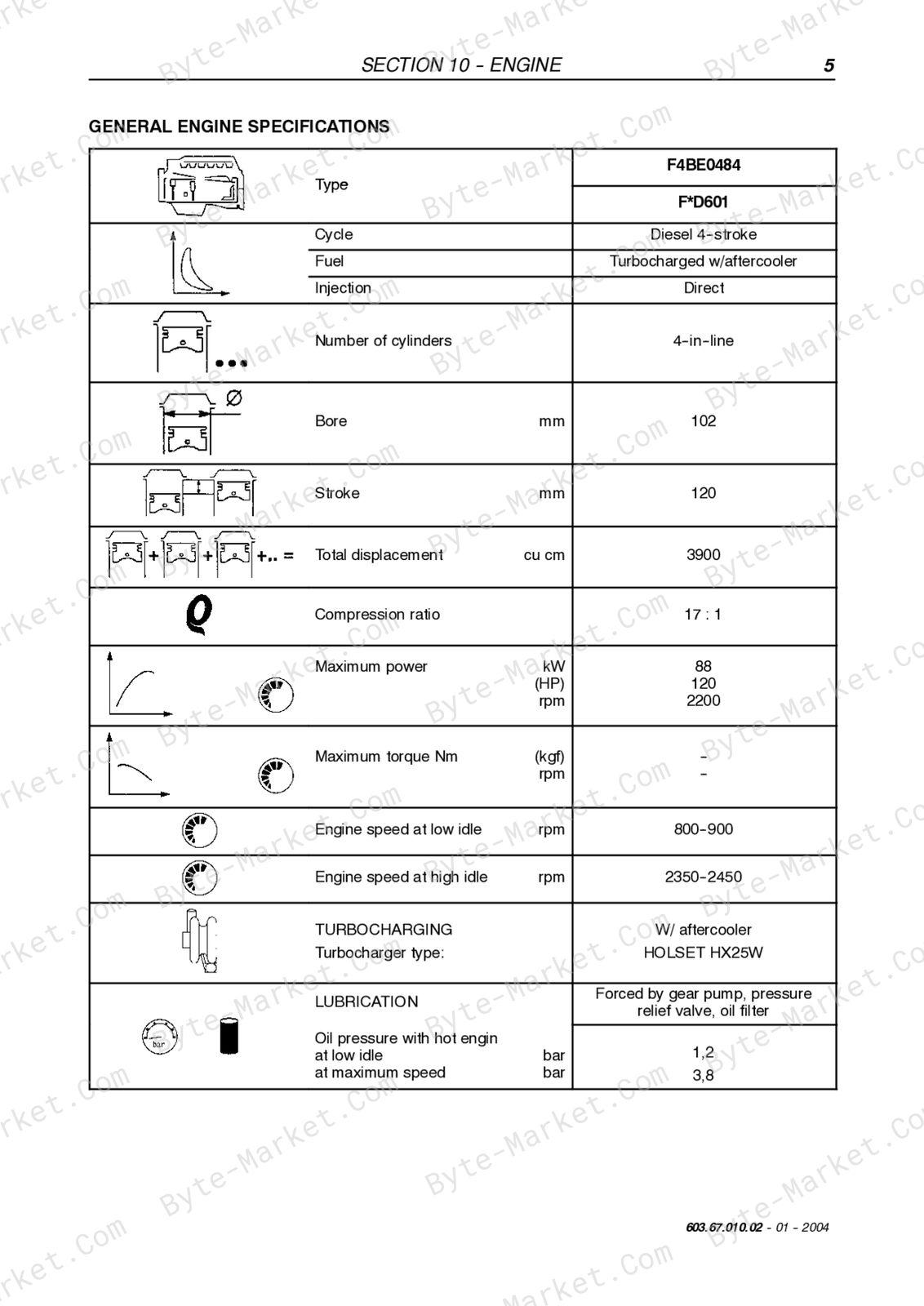
- General engine specifications — p. 45
- Generalities — p. 47
- Description of main mechanical components of the engine — p. 53
- Lubrication — p. 64
- Cooling — p. 69
- Fuel and mechanical injection — p. 71
- Injectionassembly — p. 73
- Engine overhaul on bench — p. 86
- Replacing the injectors — p. 138
- Adjustment of valve clearance — p. 140
- Setting of timing — p. 141
- Timing of the injection pump — p. 142
- Electrical components — p. 143
- Troubleshooting — p. 144
- Tooling — p. 148
- Data -- Mounting plays — p. 152
- SECTION 21 -- POWERSHIFT — p. 159
- Driving with the powershift gearbox — p. 160
- Gearbox assembly — p. 163
- Idler gear case assembly — p. 165
- Gearbox operation — p. 166
- Transmission and Hydraulic oil circuit diagrams — p. 173
- Modulation valve operation — p. 189
- Torque converter and heat exchanger hydraulic oil circuit — p. 192
- Troubleshooting guide — p. 193
- Troubleshooting procedures — p. 193
- Troubleshooting — p. 195
- Pressure testing clutch and high pressure circuit — p. 196
- Pressure testing torque converter and cooler circuit — p. 197
- Check points — p. 198
- Assembly instructions — p. 200
- Overhaul — p. 203
- Special tools — p. 262
- SECTION 25 -- FRONT AXLE — p. 263
- Description — p. 264
- Operation — p. 265
- Troubleshooting — p. 266
- Wheel toe--in check — p. 267
- Component overhaul — p. 267
- Front axle removal procedure — p. 268
- Axle drive pinion bearing adjustment — p. 314
- How to install and adjust the axle drive pinion — p. 316
- Front drive shaft — p. 319
- SECTION 27 -- REAR AXLE — p. 323
- Description — p. 324
- Operation diagram — p. 325
- Component overhaul — p. 327
- Rear axle removal procedure — p. 327
- Overhaul — p. 328
- Special tools — p. 329
- SECTION 33 -- BRAKES — p. 333
- Power brakes — p. 334
- Parking brake — p. 335
- Brake disc adjustment — p. 338
- Troubleshooting — p. 339
- Brakes disassembly — p. 340
- SECTION 35 -- HYDRAULIC SYSTEM — p. 347
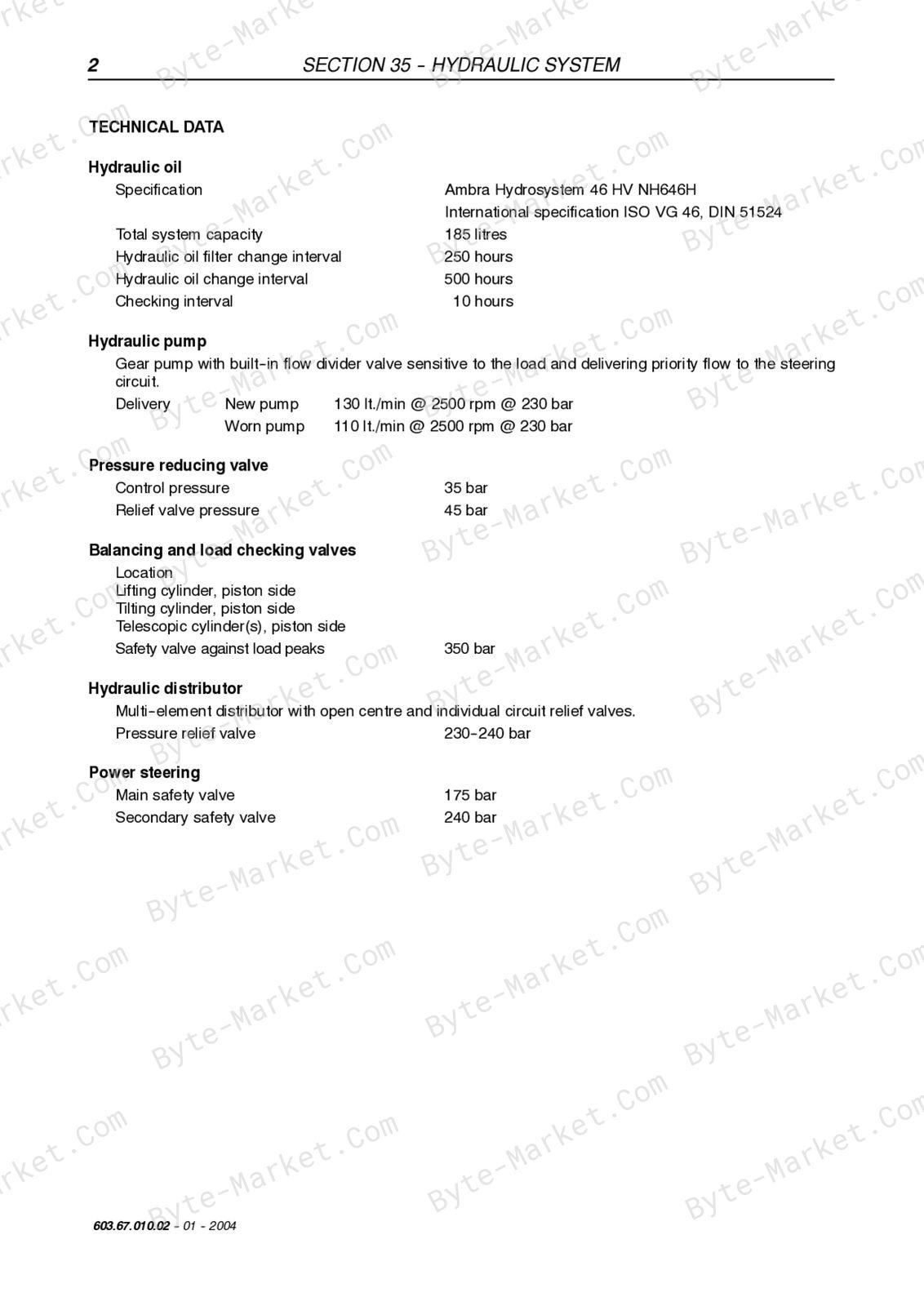
- Technical data — p. 348
- Description and operation — p. 349
- Steering system hydraulic circuit — p. 349
- Steering valve — p. 350
- Telescopic boom hydraulic circuit — p. 352
- Component operation — p. 357
- Front loader controls — p. 361
- Power steering (OSPQ) — p. 365
- Auxiliary control distributor — p. 370
- Cylinders — p. 371
- Arms — p. 381
- Working platform — p. 389
- Procedure for the calibration of the personnel carrier platform electronic controller — p. 393
- Special tools — p. 399
- SECTION 55 – ELECTRICAL SYSTEM — p. 401
- Chapter 1 – Electrical system general — p. 401
- Controls and instruments — p. 406
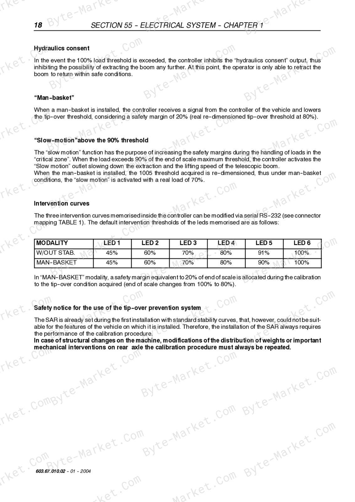
- Use of the tip--over prevention system — p. 416
- Bulb replacement — p. 423
- Protecting the electrical systems during charging or welding — p. 426
- Starting the machine using jump leads — p. 427
- Temporary wiring repairs — p. 428
- Electrical system--general fault finding — p. 430
- Working platform — p. 431
- Special tools — p. 446
-
Chapter 2 – Circuit diagrams — p. 447 — expand topics
- List of connectors — p. 448
- List of components — p. 449
- How to use the circuit diagrams — p. 451
- Diagram 1: Starter/Recharge/Warning/Indicators lights — p. 454
- Diagram 2: Transmission — p. 456
- Diagram 3: Wheel alignment/Hydraulic solenoids/Brake system — p. 458
- Diagram 4: Arm control — p. 460
- Diagram 5: Stabiliser — p. 462
- Diagram 6: Lights/Windscreen wiper — p. 464
- Diagram 7: Work lamps/Roof beacon light — p. 466
- Diagram 8: Tilting prevention system/Roof wiper — p. 468
- Diagram 9: Heating/Sound system/Electric socket/Interior lamp — p. 470
- Diagram 10: Air conditioner — p. 472
- Chapter 3 -- Wiring list — p. 473
- Cab wiring — p. 481
- Front wiring — p. 482
- Engine wiring — p. 485
- Chapter 1 – Electrical system general — p. 401
Technical reference
Reference tables include wear limits for service specifications, limits, adjustment and repair reference data. Use the values and conditions in the PDF for the applicable model and procedure.
- Service limits and settings: wear limits.
Delivery
This manual is supplied as a digital PDF file and is available for instant download after purchase. No physical media is shipped.
References
New Holland Service Manual for Telehandler, document code 603.67.010.02, PDF edition.


No questions found.