
About this manual
This New Holland repair manual covers the LS180, LS190 models.
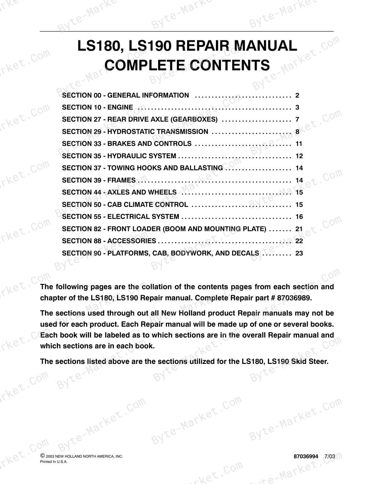
Its collated Contents lists the systems, chapters and repair topics below. Printed section-page references are retained for use with the manual.
Manual details
- Manufacturer
- New Holland
- Manual type
- Repair Manual
- Equipment type
- Skid-Steer Loader
- Models
- LS180, LS190
- Document number
- 87036989
- Text search
- Available on most pages: text layer on 943 of 948 pages.
- PDF navigation
- PDF bookmarks (limited, file-level)
- Document quality
- Clear text and illustrations on the pages checked.
Additional document information
- Contents book references
- 1: 87036990, 2: 87036991, 3: 87036992, 4: 87036993
Systems and topics in this manual
General Information
Listed topics include Parts and Accessories, Model Codes, Precautionary Statements.
Engine
The section includes LS180 - 332T/JF; LS190 - 450/NC. Listed topics include LS 180 Engine Services, Engine Model and Serial Number Location, General Engine Information.
Rear Drive Axle (Gearboxes)
Listed topics include Troubleshooting, Testing, Gearboxes.
Hydrostatic Transmission
Listed topics include Operation, Troubleshooting, Low Power Through the Engine/Transmission System.
Brakes And Controls
Listed topics include Troubleshooting, Testing, Parking Brake.
Hydraulic System
Listed topics include Hydraulic System Compatibility, Boom Cylinder Pivot Pins, Boom Cylinder Pivot Pin Location and Machine Usage.
Towing Hooks And Ballasting
Listed topics include Rear Counterweights, Rear Counterweight Support Removal.
Frames
Listed topics include ROPS, ROPS Frame, ROPS Removal.
Axles And Wheels
Listed topics include Troubleshooting, Testing, Axles.
Cab Climate Control
Listed topics include Heater/Defroster (Cab), Evaluation Procedure, Heater/Defroster System Troubleshooting.
Electrical System
Listed topics include Adapting Attachments Requiring 12V Electrical Power, Electrical Diagram, Advanced Warning System.
Front Loader (Boom And Mounting Plate)
Listed topics include Buckets, Boom Lock Pins and Linkage, Boom.
Accessories
Listed topics include Adapting Attachments Requiring 12V Electrical Power, Hydraulic System Compatibility, Arm Pads For Cab Side Panels.
Platform, Cab, Bodywork, And Decals
Listed topics include Seat and Seat Pan Support, Cab Inner Shell, Seat Removal.
Manual contents
The references below use the page numbering printed in the manual.
General Information
- Introduction (ref. 00-2)
- About Improvements (ref. 00-2)
- Company Policy (ref. 00-3)
- Parts and Accessories (ref. 00-3)
- Model Codes (ref. 00-3)
- Precautionary Statements (ref. 00-4)
- Safety Precaution Information (ref. 00-5)
- General Safety Information (ref. 00-7)
- Machine Model and Serial Number Location (ref. 00-9)
- Engine Model and Serial Number Location (ref. 00-9)
- Hardware Torque Specifications (ref. 00-10)
- Installation of Adjustable Fittings in Straight Thread O Ring Bosses (ref. 00-12)
- Standard Torque Data for Hydraulic Tubes and Fittings (ref. 00-12)
- Pipe Thread Fitting Torque (ref. 00-13)
- Lubricants and Coolants (ref. 00-13)
- Sealants (ref. 00-13)
- Properly Support a Raised Machine (ref. 00-14)
- Properly Support Boom on Boom Lock Pins (ref. 00-14)
- Raising Boom Without Hydraulic Oil Flow (ref. 00-14)
- Raising Boom Without Battery Voltage (12V) (ref. 00-15)
- Reattaching Cylinders After Repair with Boom Resting on Boom Lock Pins (ref. 00-17)
- Major Unit Overhaul (ref. 00-18)
- Cab and Boom Tilt Procedure (ref. 00-19)
- Craning the Skid Steer (ref. 00-25)
- Special Tools (ref. 00-28)
- Specifications (Model LS180) (ref. 00-29)
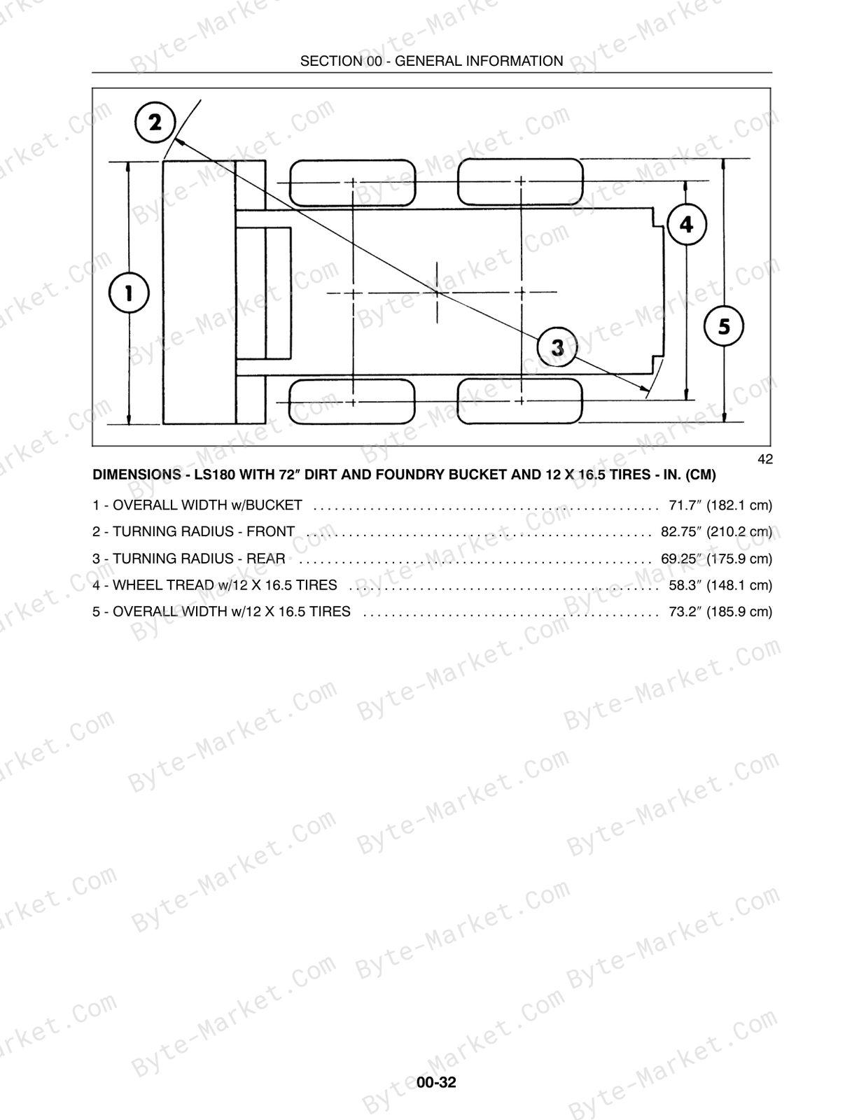
- Dimensions (Model LS180) (ref. 00-32)
- Specifications (Model LS190) (ref. 00-34)
- Dimensions (Model LS190) (ref. 00-37)
Engine — Chapter 1 - - LS180 - 332T/JF
- Introduction (ref. 10-3)
- Safety Precautions (ref. 10-3)
- LS 180 Engine Services (ref. 10-4)
- Engine Model and Serial Number Location (ref. 10-4)
- General Engine Information (ref. 10-4)
- General Engine Specifications (ref. 10-8)
- Troubleshooting (ref. 10-10)
- Specifications Service Standards (ref. 10-19)
- Hardware Torque Chart (ref. 10-26)
- Torque Specifications (ref. 10-27)
- Turbocharger Torque Specifications (ref. 10-28)
- Engine Electrical Components - LS180 (ref. 10-29)
- Engine Removal By Tilting Cab and Boom Forward (ref. 10-30)
- Mounting the Engine for Maintenance (ref. 10-35)
- Engine Disassembly Sequence (ref. 10-35)
- Engine Component Maintenance (ref. 10-36)
- Cylinder Block, Pistons, Rings, Rods and Bearings (ref. 10-45)
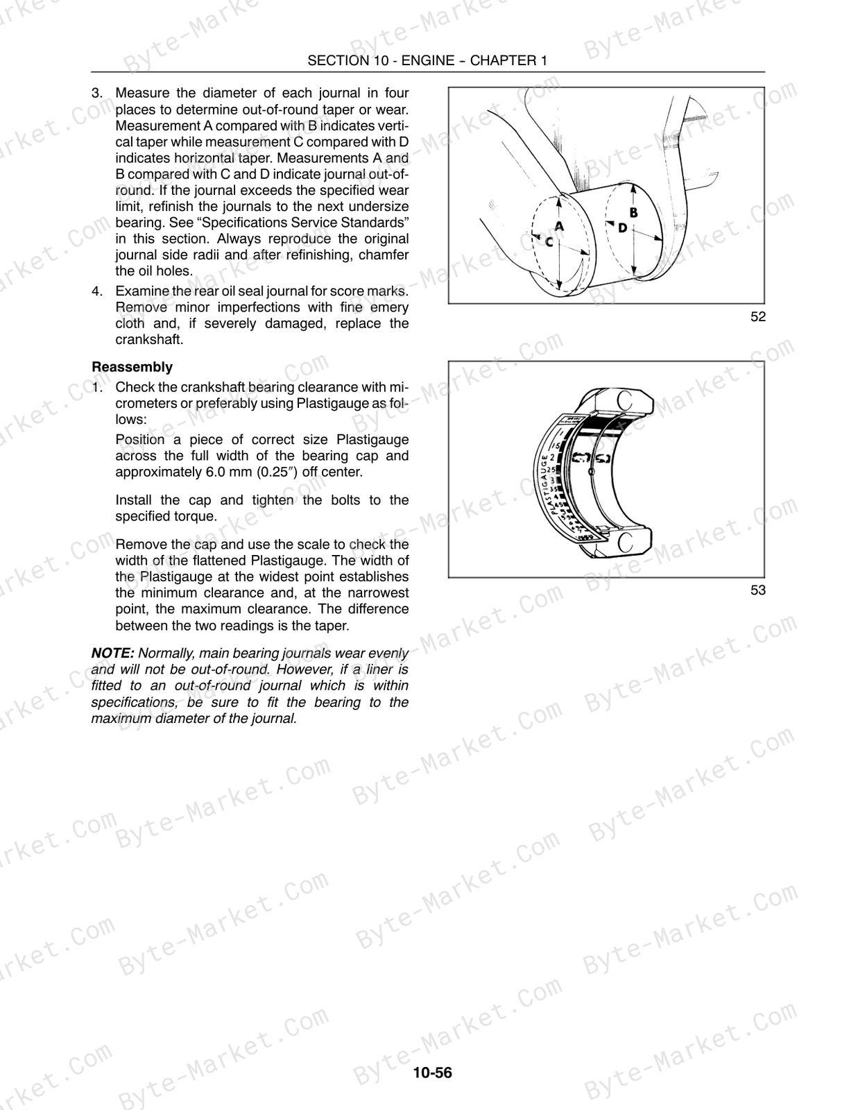
- Crankshaft, Main Bearings, and Flywheel (ref. 10-53)
- Camshaft and Timing Gear Train (ref. 10-59)
- Timing Gear (ref. 10-62)
- Engine Timing (ref. 10-66)
- Cooling System (ref. 10-70)
- Thermostat Removal (ref. 10-71)
- Water Pump Removal (ref. 10-72)
- Lubrication System (ref. 10-77)
- Oil Pan Removal (ref. 10-77)
- Oil Pump Removal (ref. 10-78)
- Oil Level Dipstick (ref. 10-81)
- Fuel System (ref. 10-82)
- Electric Lift Pump (ref. 10-82)
- Injectors (ref. 10-90)
- Fuel Injector Overhaul (ref. 10-92)
- Electric Lift Pump (ref. 10-95)
- Fuel Tank (ref. 10-97)
- Air Intake and Exhaust System (ref. 10-100)
- Exhaust Muffler (ref. 10-102)
- Turbocharger (ref. 10-103)
- Starting a Turbocharged Engine After Installation of a Turbocharger (ref. 10-112)
- Engine Installation (ref. 10-113)
- Operating the Engine After Overhaul (ref. 10-116)
- Electrical Component Maintenance (ref. 10-117)
- Adjust Belt Tension (ref. 10-118)
Engine — Chapter 2 - - LS190 - 450/NC
- Introduction (ref. 10-125)
- Safety Precautions (ref. 10-125)
- LS 180 Engine Services (ref. 10-126)
- General Engine Information (ref. 10-126)
- General Engine Specifications (ref. 10-130)
- Troubleshooting (ref. 10-131)
- Specifications Service Standards (ref. 10-141)
- Hardware Torque Chart (ref. 10-147)
- Torque Specifications (ref. 10-148)
- Engine Electrical Components - LS190 (ref. 10-149)
- Engine Removal By Tilting Cab and Boom Forward (ref. 10-150)
- Mounting the Engine for Maintenance (ref. 10-157)
- Engine Disassembly Sequence (ref. 10-157)
- Engine Component Maintenance (ref. 10-158)
- Cylinder Head Reassembly (ref. 10-166)
- Cylinder Head Installation (ref. 10-166)
- Engine Front Cover and TIming Gear Removal (ref. 10-167)
- Camshaft Drive Gear (ref. 10-168)
- Engine Timing (ref. 10-171)
- Oil Pan Removal (ref. 10-175)
- Connecting Rods, Bearings, Pistons, and Rings Removal (ref. 10-175)
- Connecting Rod Bushing (ref. 10-178)
- Cylinder Block Overhaul (ref. 10-180)
- Cylinder Bore (ref. 10-181)
- Sleeve - Boring and Honing (ref. 10-182)
- Balancer/Vibration Damper (ref. 10-187)
- Main Bearing Removal (ref. 10-188)
- Flywheel Removal (ref. 10-189)
- Rear Cover Plate Removal (ref. 10-190)
- Oil Pump Removal (ref. 10-192)
- Crankshaft Removal (ref. 10-194)
- Crankshaft Reassembly (ref. 10-196)
- Camshaft Removal (ref. 10-197)
- Camshaft Bearings (ref. 10-198)
- Engine Compression Test (ref. 10-199)
- Cooling System (ref. 10-200)
- Radiator (ref. 10-200)
- Thermostat Removal (ref. 10-200)
- Fan Belt Tensioner Removal (ref. 10-202)
- Idler Pulley (ref. 10-203)
- Water Pump Removal (ref. 10-203)
- Lubrication System (ref. 10-208)
- Oil Level Dipstick (ref. 10-208)
- Fuel System (ref. 10-213)
- Sediment Separator (ref. 10-214)
- Thermostat (ref. 10-214)
- Fuel Filter (ref. 10-214)
- Injectors (ref. 10-215)
- Verifying Pup Timing (ref. 10-218)
- Installing the Injection Pump (ref. 10-219)
- Electric Lift Pump (ref. 10-223)
- Injectors (ref. 10-225)
- Fuel Injector Overhaul (ref. 10-225)
- Fuel Tank (ref. 10-232)
- Air Intake and Exhaust System (ref. 10-234)
- Manifolds (ref. 10-237)
- Engine Installation (ref. 10-239)
- Operating the Engine After Overhaul (ref. 10-245)
- Electrical Component Maintenance (ref. 10-246)
- Charging Circuit (ref. 10-247)
- Adjust Belt Tension (ref. 10-247)
- Special Tools (ref. 10-248)
Rear Drive Axle (Gearboxes) — Chapter 1 - - Gearboxes
- General Information (ref. 27-2)
- Specifications (ref. 27-4)
- Troubleshooting (ref. 27-5)
- Testing (ref. 27-7)
- Gearboxes (ref. 27-8)
- Final Drive and Gearbox Fill/Check Plug (2) (ref. 27-8)
- Gearbox Removal (ref. 27-9)
- Gearbox Disassembly (ref. 27-10)
- Gearbox Parts Inspection (ref. 27-14)
- Gearbox Reassembly (ref. 27-15)
- Gearbox Reinstallation (ref. 27-18)
- Engine-to-Transmission Gearbox (ref. 27-23)
- Engine-to-Transmission Gearbox Removal - Disassembly (ref. 27-23)
- Engine-to-Transmission Gearbox Parts Inspection (ref. 27-28)
- Engine-to-Transmission Gearbox Reassembly - Installation (ref. 27-29)
- Start-Up Procedure (ref. 27-32)
Hydrostatic Transmission — Chapter 1 - - Neutralizer, Pumps, Motors, Two-Speed
- General Information (ref. 29-4)
- Operation (ref. 29-4)
- Specifications (ref. 29-6)
- Troubleshooting (ref. 29-8)
- Low Power Through the Engine/Transmission System (ref. 29-10)
- Hydrostatic Drive System Testing (ref. 29-13)
- Hydrostatic System Oil Flow (ref. 29-16)
- Hydrostatic Charge System Pressure Test (ref. 29-19)
- Hydrostatic Pump Case Drain Test (ref. 29-21)
- Hydrostatic Pump High Pressure Test (ref. 29-23)
- Hydrostatic Motor Case Drain Test (ref. 29-25)
- Hydraulic, Hydrostatic System Air Ingress Test (ref. 29-27)
- Hydrostatic and Charge Pumps (ref. 29-29)
- Hydrostatic Pumps (ref. 29-29)
- Hydrostatic Pump Removal (ref. 29-29)
- Hydrostatic and Charge Pump Disassembly (ref. 29-35)
- Hydrostatic Charge Pump (ref. 29-36)
- Hydrostatic Charge Pump Disassembly (ref. 29-36)
- Hydrostatic Charge Pump Parts Inspection (ref. 29-37)
- Hydrostatic Charge Pump Reassembly (ref. 29-38)
- Hydrostatic Pump (ref. 29-39)
- Hydrostatic Pump Disassembly (ref. 29-39)
- Hydrostatic Pump Parts Inspection (ref. 29-44)
- Hydrostatic Pump Reassembly (ref. 29-50)
- Hydrostatic Pump Reinstallation (ref. 29-58)
- Motors (ref. 29-62)
- Hydrostatic Motor - Single Speed (ref. 29-62)
- Hydrostatic Motor - Single Speed Removal (ref. 29-62)
- Hydrostatic Motor - Single Speed Disassembly (ref. 29-66)
- Hydrostatic Motor - Single Speed Parts Inspection (ref. 29-69)
- Hydrostatic Motor - Single Speed Reassembly (ref. 29-73)
- Hydrostatic Motor - Single Speed Reinstallation (ref. 29-77)
- Hydrostatic Motor - Two Speed (ref. 29-79)
- Hydrostatic Motor - Two Speed Removal (ref. 29-79)
- Hydrostatic Motor - Two Speed Disassembly (ref. 29-84)
- Hydrostatic Motor - Two Speed Parts Inspection (ref. 29-88)
- Hydrostatic Motor - Two Speed Reassembly (ref. 29-92)
- Hydrostatic Motor - Two Speed Reinstallation (ref. 29-98)
- Two Speed High/Low Range Components (ref. 29-101)
- Two Speed High/Low Control Valve (ref. 29-103)
- Two Speed High/Low Control Valve Removal (ref. 29-104)
- Two Speed High/Low Control Valve Disassembly (ref. 29-105)
- Two Speed High/Low Control Valve Inspection (ref. 29-105)
- Two Speed High/Low Control Valve Reassembly (ref. 29-106)
- Control Valve Reinstallation (ref. 29-107)
- Two Speed High/Low Slave Cylinder (ref. 29-108)
- Two Speed High/Low Slave Cylinder Removal (ref. 29-109)
- Two Speed High/Low Slave Cylinder Disassembly (ref. 29-109)
- Two Speed High/Low Slave Cylinder Inspection (ref. 29-110)
- Two Speed High/Low Slave Cylinder Reassembly (ref. 29-110)
- Two Speed High/Low Slave Cylinder Reinstallation (ref. 29-110)
- Two Speed High/Low Motor Control Linkage (ref. 29-111)
- Two Speed High/Low Motor Control Linkage Removal (ref. 29-112)
- Two Speed High/Low Motor Control Linkage Inspection (ref. 29-113)
- Two Speed High/Low Motor Control Linkage Reinstallation (ref. 29-114)
- Two Speed Control Switch (ref. 29-115)
- Hydraulic System Cleaning Procedure (ref. 29-116)
- Start-up Procedure After Rebuild (After Pump or Motor Replacement) (ref. 29-119)
- Steering System (ref. 29-122)
- Hydrostatic System Controls (ref. 29-122)
- Neutralizer Assembly (ref. 29-124)
- Neutralizer Assembly Removal (ref. 29-124)
- Neutralizer Assembly Disassembly (ref. 29-124)
- Neutralizer Assembly Inspection (ref. 29-125)
- Neutralizer Assembly Reassembly (ref. 29-127)
- Control Linkage (ref. 29-129)
- Control Linkage Removal (ref. 29-129)
- Control Linkage Disassembly (ref. 29-129)
- Control Linkage Inspection (ref. 29-129)
- Control Linkage Reassembly (ref. 29-130)
- Left Control Handle With No Boom Control (ref. 29-131)
- Left Control Handle With No Boom Control Removal (ref. 29-131)
- Left Control Handle With No Boom Control Disassembly (ref. 29-131)
- Left Control Handle With No Boom Control Inspection (ref. 29-132)
- Left Control Handle With No Boom Control Reassembly (ref. 29-132)
- Left Control Handle With No Boom Control Reinstallation (ref. 29-132)
- Left Control Handle With Boom Control (ref. 29-134)
- Left Control Handle With Boom Control Removal (ref. 29-134)
- Left Control Handle With Boom Control Disassembly (ref. 29-135)
- Left Control Handle With Boom Control Inspection (ref. 29-136)
- Left Control Handle With Boom Control Reassembly (ref. 29-137)
- Left Control Handle With Boom Control Reinstallation (ref. 29-138)
- Right Control Handle With Auxiliary or Bucket Control (ref. 29-140)
- Right Control Handle With Auxiliary or Bucket Control Removal (ref. 29-140)
- Right Control Handle With Auxiliary or Bucket Control Disassembly (ref. 29-141)
- Right Control Handle With Auxiliary or Bucket Control Inspection (ref. 29-143)
- Right Control Handle With Auxiliary or Bucket Control Reassembly (ref. 29-144)
- Right Control Handle With Auxiliary or Bucket Control Reinstallation (ref. 29-147)
- Control Linkage and Neutralizer (ref. 29-149)
- Control Linkage and Neutralizer Reinstallation (ref. 29-149)
- Drive Control Adjustment Procedure (ref. 29-150)
- LS180 Links and Arms (ref. 29-151)
- LS180 Neutralizer Adjustment (ref. 29-152)
- Control Lever Parallel Adjustment (ref. 29-153)
- LS180 Linkage and Control Lever Equal Movement (ref. 29-153)
- Left Control Linkage Adjustment (ref. 29-154)
- LS180 Straight Travel and Forward/Reverse Stop Adjustment (ref. 29-154)
- LS190 Links and Arms (ref. 29-157)
- LS190 Neutralizer Adjustment (ref. 29-157)
- LS190 Hydrostatic Control Lever (ref. 29-158)
- LS190 Linkage and Control Lever Equal Movement (ref. 29-158)
- Left Control Linkage Adjustment (ref. 29-159)
- LS190 Straight Travel and Forward/Reverse Stop Adjustment (ref. 29-159)
- LS190 and LS190 High/Low Range Adjustment (Optional on LS180) (ref. 29-162)
Brakes And Controls — Chapter 1 - - Parking Brake
- General Information (ref. 33-2)
- Specifications (ref. 33-3)
- Troubleshooting (ref. 33-4)
- Testing (ref. 33-6)
- Parking Brake (ref. 33-7)
- Parking Brake Removal and Inspection (ref. 33-8)
- Parking Brake Adjustment (ref. 33-13)
Hydraulic System — Chapter 1 - - Valves, Gear Pump, Cylinders, and Pedal Controls
- General Information (ref. 35-3)
- Hydraulic System Compatibility (ref. 35-4)
- Boom Cylinder Pivot Pins (ref. 35-6)
- Boom Cylinder Pivot Pin Location and Machine Usage (ref. 35-6)
- Control Valve Power Beyond (ref. 35-7)
- Specifications (ref. 35-8)
- Troubleshooting (ref. 35-11)
- Auxiliary Boom Hydraulics Troubleshooting (ref. 35-15)
- Hydraulic System Testing (ref. 35-17)
- Hydraulic System Oil Flow (Neutral Position) (ref. 35-23)
- Control Valve - Bucket Spool Shifted (ref. 35-24)
- Control Valve - Boom Spool Shifted (ref. 35-25)
- Control Valve - Auxiliary Spool Shifted (ref. 35-26)
- Hydraulic System Oil Flow (ref. 35-27)
- Main System Pressure Tests (ref. 35-29)
- Checking Main System Pressure at Boom Cylinders (ref. 35-32)
- Checking Main System Pressure at Bucket Cylinders (ref. 35-33)
- Checking Main System Pressure at Auxiliary Boom Hydraulic Quick Couplers (ref. 35-34)
- Boom Circuit Relief Valve Test (ref. 35-35)
- Gear Pump Flow Efficiency Test (ref. 35-37)
- Boom and Bucket Spool Lock Solenoid Test (ref. 35-40)
- Hydraulic, Hydrostatic System Air Ingress Test (ref. 35-42)
- Control Valve Specifications (ref. 35-44)
- Control Valve Removal (ref. 35-45)
- Control Valve Disassembly and Inspection (ref. 35-47)
- Control Valve Parts Inspection (ref. 35-51)
- Control Valve Reassembly (ref. 35-52)
- Control Valve Reinstallation (ref. 35-56)
- Hydraulic Pump Specifications (ref. 35-57)
- Hydraulic Pump Removal (ref. 35-58)
- Hydraulic Pump Disassembly (ref. 35-61)
- Hydraulic Pump Parts Inspection (ref. 35-62)
- Hydraulic Pump Reassembly (ref. 35-65)
- Hydraulic Pump Installation (ref. 35-68)
- Cylinders, Boom and Bucket (ref. 35-72)
- Boom Cylinder Removal (ref. 35-74)
- Boom Cylinder Disassembly (ref. 35-75)
- Boom Cylinder Parts Inspection (ref. 35-77)
- Boom Cylinder Reassembly (ref. 35-78)
- Boom Cylinder Reinstallation (ref. 35-80)
- Bucket Cylinder Removal (ref. 35-81)
- Bucket Cylinder Disassembly (ref. 35-81)
- Bucket Cylinder Parts Inspection (ref. 35-82)
- Bucket Cylinder Reassembly (ref. 35-84)
- Bucket Cylinder Reinstallation (ref. 35-86)
- Pedal Controls (ref. 35-87)
- Pedal Removal (With Boom and Bucket Pedal Controls) (ref. 35-87)
- Pedal Inspection (With Boom and Bucket Pedal Controls) (ref. 35-87)
- Pedal Reinstallation (With Boom and Bucket Pedal Controls) (ref. 35-89)
- Pedal Removal (With Boom and Bucket Hand Controls) (ref. 35-92)
- Pedal Inspection (With Boom and Bucket Hand Controls) (ref. 35-93)
- Pedal Reinstallation (With Boom and Bucket Hand Controls) (ref. 35-94)
- Hydraulic Cooling, Filter, Reservoir System (ref. 35-97)
- Filter System (ref. 35-98)
- Filter Removal (ref. 35-98)
- Base Removal (ref. 35-98)
- Reassembly (ref. 35-99)
- Oil Cooler (ref. 35-100)
- Oil Cooler Removal (ref. 35-100)
- Oil Cooler Reassembly (ref. 35-100)
- Oil Reservoir (ref. 35-101)
- Oil Reservoir Removal (ref. 35-102)
- Oil Reservoir Inspection (ref. 35-103)
- Oil Reservoir Reinstallation (ref. 35-104)
- Adapting Attachments (ref. 35-105)
Towing Hooks And Ballasting — Chapter 1 - - Rear Counter Weights
- Rear Counterweights (ref. 37-2)
- Rear Counterweight Support Removal (ref. 37-2)
Frames — Chapter 1 - - Lower Main, ROPS
- General Information (ref. 39-2)
- ROPS (ref. 39-2)
- ROPS Frame (ref. 39-2)
- ROPS Removal (ref. 39-2)
- ROPS Reinstallation (ref. 39-9)
Axles And Wheels — Chapter 1 - - Axles
- General Information (ref. 44-2)
- Specifications (ref. 44-4)
- Troubleshooting (ref. 44-5)
- Testing (ref. 44-7)
- Axles (ref. 44-8)
- Axle Housing Assembly Removal (ref. 44-8)
- Axle Disassembly (ref. 44-9)
- Axle Parts Inspection (ref. 44-11)
- Axle Reassembly (ref. 44-12)
- Axle Housing Reinstallation (ref. 44-14)
- Final Drive (ref. 44-16)
- Drive Chain and Sprocket Removal (ref. 44-16)
- Final Drive Parts Inspection (ref. 44-18)
- Final Drive Reassembly (ref. 44-19)
- Tires/Wheels (ref. 44-22)
- Tire and Track Installation (ref. 44-23)
Cab Climate Control — Chapter 1 - - Heater/Defroster
- Heater/Defroster (Cab) (ref. 50-2)
- Evaluation Procedure (ref. 50-8)
- Heater/Defroster System Troubleshooting (ref. 50-9)
- Heater/Defroster Schematic/Wiring Diagram (ref. 50-18)
Electrical System — Chapter 1 - - Advanced Warning System, Circuits, Alternator, and Starter
- General Electrical Information (ref. 55-6)
- Definition of Terms (ref. 55-7)
- Adapting Attachments Requiring 12V Electrical Power (ref. 55-9)
- Specifications (ref. 55-12)
- Electrical Diagram (ref. 55-15)
- Advanced Warning System (ref. 55-19)
- Electronic Instrument Cluster (EIC) (ref. 55-19)
- (EIC) Electronic Instrument Cluster Front Panel (ref. 55-20)
- EIC Functional Groups (ref. 55-21)
- Engine Preheat (ref. 55-26)
- Automatic Shutdown (ref. 55-26)
- Operating Mode (ref. 55-27)
- Broken Alternator/Water Pump Belt Warning (ref. 55-29)
- Fuel Level (ref. 55-30)
- EIC Interlocks (ref. 55-30)
- EIC Lock Mode (ref. 55-31)
- EIC Engine Preheat (ref. 55-32)
- Troubleshooting (ref. 55-33)
- Advanced Warning System (AWS) (ref. 55-36)
- EIC Board Self Test (ref. 55-37)
- Diagnostic and Setup Modes (ref. 55-38)
- Arrow, Open Book, and Audible Alarm Test (ref. 55-40)
- Diagnostic Mode EIC Circuit Tests (ref. 55-40)
- EIC Setup Mode (ref. 55-44)
- Electronic Instrument Cluster (EIC) and Starter Circuits (ref. 55-52)
- Blown Fuse Symptom and Testing (ref. 55-52)
- Testing Other EIC Functions (ref. 55-54)
- EIC Board Reading Accuracy (ref. 55-57)
- EIC Board Claims Warranty (ref. 55-60)
- Electrical Circuits (ref. 55-61)
- Seat Switch Circuit to EIC Board (ref. 55-62)
- Seat Belt Switch Circuit to EIC Board (ref. 55-63)
- Ignition Switch Circuit to EIC Board (ref. 55-64)
- Cranking Circuit (Starter Motor) (ref. 55-65)
- Service/Run Switch in the Run Position (ref. 55-66)
- Cranking Circuit Ground (ref. 55-67)
- Service/Run Switch in the Service position (ref. 55-68)
- Cranking Circuit Ground (ref. 55-69)
- Start Relay Operation (ref. 55-69)
- Start Relay Circuit (ref. 55-70)
- Start Relay Ground Circuit (ref. 55-71)
- Start Interlock Relay Operation (ref. 55-71)
- Start Interlock Circuit (ref. 55-72)
- Start Interlock Ground Circuit (ref. 55-73)
- Start Circuit (ref. 55-73)
- Removal, Installation and Wiring of Electrical Components (ref. 55-74)
- Battery - LS180 (ref. 55-75)
- Battery Removal - LS180 (ref. 55-75)
- Battery Installation - LS180 (ref. 55-75)
- Battery Removal - LS190 (ref. 55-76)
- EIC (Electronic Instrument Cluster) Board Removal (ref. 55-77)
- EIC (Electronic Instrument Cluster) Wiring (ref. 55-78)
- EIC (Electronic Instrument Cluster) Board Installation (ref. 55-79)
- Ignition (Key) Switch Wiring (ref. 55-79)
- Ignition (Key) Switch Removal (ref. 55-80)
- Ignition (Key) Switch Installation (ref. 55-80)
- Cab Fuse Panel Wiring (ref. 55-81)
- Cab Fuse Block and Panel Removal (ref. 55-82)
- Cab Fuse Block and Panel Installation (ref. 55-82)
- Service/Run Switch Wiring (ref. 55-83)
- Service/Run Switch - Service Position (ref. 55-83)
- Service/Run Switch - Run Position (ref. 55-83)
- Service/Run Switch Removal (ref. 55-84)
- Service/Run Switch Installation (ref. 55-84)
- Seat and Seat Belt Switch Wiring (ref. 55-84)
- Seat Switch Removal (ref. 55-85)
- Seat Switch Installation (ref. 55-85)
- Seat Belt Buckle and Switch Assembly Removal (ref. 55-86)
- Seat Belt Buckle Installation (ref. 55-86)
- Road Light and Work Light Switch Wiring (ref. 55-86)
- Road Light and Work Light Switch Removal (ref. 55-87)
- Road Light and Work Light Switch Installation (ref. 55-87)
- Engine Fuse and Relay Panel (ref. 55-88)
- Accessory Relay Wiring (ref. 55-89)
- Accessory Relay Removal (ref. 55-89)
- Accessory Relay Installation (ref. 55-89)
- Preheat Circuit Breaker Wiring (ref. 55-89)
- Preheat Circuit Breaker Removal (ref. 55-89)
- Preheat Circuit Breaker Installation (ref. 55-89)
- Start Interlock Relay Wiring (ref. 55-90)
- Start Interlock Relay Removal (ref. 55-91)
- Start Interlock Relay Installation (ref. 55-91)
- Engine Fuse Panel Wiring (ref. 55-91)
- Engine Fuse Block Removal (ref. 55-92)
- Engine Fuse Block Installation (ref. 55-92)
- Alternator Excite Resistor Wiring (ref. 55-93)
- Alternator Excite Resistor Removal (ref. 55-93)
- Alternator Excite Resistor Installation (ref. 55-93)
- Start Relay Wiring (ref. 55-94)
- Start Relay Removal (ref. 55-94)
- Start Relay Installation (ref. 55-95)
- Preheat Relay Wiring (ref. 55-95)
- Preheat Relay Removal (ref. 55-96)
- Preheat Relay Installation (ref. 55-96)
- Preheat Manifold Heater Removal (ref. 55-96)
- Preheat Manifold Heater Installation (ref. 55-96)
- Fuel System Components (ref. 55-97)
- Fuel Shutoff Solenoid (ref. 55-99)
- Fuel Shutoff Solenoid Testing (ref. 55-99)
- Replacement of Fuel Shutoff Solenoid (ref. 55-100)
- Electric Lift Pump (ref. 55-100)
- Electric Lift Pump Removal (ref. 55-101)
- Cold Advance Switch Removal (ref. 55-101)
- Cold Advance Switch Installation (ref. 55-101)
- Air Filter Restriction Indicator Switch Removal (ref. 55-101)
- Air Filter Restriction Indicator Switch Installation (ref. 55-101)
- Engine Coolant Temperature Sender Removal (ref. 55-102)
- Engine Coolant Temperature Sender Installation (ref. 55-102)
- Engine Oil Pressure Switch Removal (ref. 55-103)
- Engine Oil Pressure Switch Installation (ref. 55-103)
- Hydrostatic Charge Pressure Switch Removal (ref. 55-103)
- Hydrostatic Charge Pressure Switch Installation (ref. 55-103)
- Hydraulic Oil Filter Restriction Switch Removal (ref. 55-104)
- Hydraulic Oil Filter Restriction Switch Installation (ref. 55-104)
- Hydraulic Oil Temperature Sender Removal (ref. 55-104)
- Hydraulic Oil Temperature Sender Installation (ref. 55-106)
- Boom/Bucket Control Valve Spool Lock Solenoids (ref. 55-106)
- Boom/Bucket Control Valve Spool Lock Solenoids Removal (ref. 55-106)
- Boom/Bucket Control Valve Spool Lock Solenoids Installation (ref. 55-107)
- Wire Harness (ref. 55-108)
- Main Wire Harness Removal (ref. 55-108)
- Main Wire Harness Installation (ref. 55-113)
- Road/Work Lights (ref. 55-117)
- Alternator (40 Amp Version) (ref. 55-121)
- Charging Circuit (ref. 55-121)
- Alternator Service Specifications (ref. 55-123)
- Alternator System Testing and Troubleshooting (ref. 55-123)
- Alternator Component Tests (ref. 55-127)
- Alternator Overhaul Component Testing (ref. 55-129)
- Alternator Removal (ref. 55-129)
- Alternator Disassembly (ref. 55-130)
- Alternator Component Test (ref. 55-131)
- Alternator Inspection and Repair (ref. 55-133)
- Alternator Reassembly (ref. 55-134)
- Alternator Reinstallation (ref. 55-134)
- Starter (ref. 55-135)
- Starter Motor Troubleshooting (ref. 55-137)
- Starter Motor Removal (ref. 55-138)
- Starter Maintenance (ref. 55-139)
- System Testing (ref. 55-139)
- System Motor Current Draw (ref. 55-140)
- Starter Motor Disassembly (ref. 55-142)
- Starter Reassembly (ref. 55-143)
- Starter Inspection and Repair (ref. 55-143)
Front Loader (Boom And Mounting Plate) — Chapter 1 - - Buckets
- General Information (ref. 82-2)
- Buckets (ref. 82-2)
- Boom Lock Pins and Linkage (ref. 82-3)
- Boom (ref. 82-3)
- Attachment Mounting Plate (ref. 82-4)
- Boom and Cylinder Pivot Pins (ref. 82-4)
- Boom and Cylinder Pivot Pin Location and Machine Usage (ref. 82-4)
- Boom and Cylinder Pivot Pins Size (ref. 82-5)
- Pallet Fork (ref. 82-6)
- Utility Fork (ref. 82-7)
- Bucket Cutting Edge (Replacement) (ref. 82-8)
- Bucket Latch Plate Installation Procedure (ref. 82-9)
- Dirt Tooth Kit Installation (ref. 82-12)
- Bucket Tooth Spacing (ref. 82-13)
- Boom Lock Pin/Linkage (ref. 82-15)
- Boom Lock Pin/Linkage Removal (ref. 82-15)
- Boom Lock Pin/Linkage Reinstallation (ref. 82-17)
- Boom, Upper and Lower Link (ref. 82-18)
- Boom, Upper and Lower Link Removal (ref. 82-18)
- Front Boom Mounting Plate Pivot Hub Replacement (ref. 82-22)
- Boom, Upper and Lower Link Reinstallation (ref. 82-25)
- Attachment Mounting Plate (ref. 82-30)
- Attachment Mounting Plate Removal (ref. 82-30)
- Repair/Rebuild Mounting Plate (ref. 82-30)
- Latch Lever and Pin Removal/Repair (ref. 82-30)
- Attachment Mounting Plate Parts Inspection (ref. 82-33)
- Checking Procedure for Buckets and Attachments (ref. 82-38)
- Checking Procedure (ref. 82-40)
- Checking the Loader Faceplate (ref. 82-41)
Accessories — Chapter 1 - - Dealer Installed Options
- General Information (ref. 88-2)
- Adapting Attachments Requiring 12V Electrical Power (ref. 88-2)
- Hydraulic System Compatibility (ref. 88-5)
- Arm Pads For Cab Side Panels (ref. 88-7)
- Armrests for Deluxe Seat (ref. 88-7)
- Forearm Rests (ref. 88-8)
- Back-up Alarm (ref. 88-9)
- Block Heater (Engine) (ref. 88-10)
- Electric Power Supply (12 Volt, 15 Amp) (ref. 88-12)
- Exhaust (Engine) (ref. 88-13)
- Aspirator Precleaner Muffler (ref. 88-13)
- High Flow Hydraulics (ref. 88-14)
- High Flow Hydraulics Troubleshooting (ref. 88-16)
- High Flow Hydraulics Component Replacement (ref. 88-18)
- High Flow Hydraulics Operation (ref. 88-21)
- Horn (ref. 88-25)
- Shoulder Belt (Seat) (ref. 88-26)
- Slow-moving Vehicle (SMV) Sign Kit (ref. 88-27)
- Tires/Wheels (ref. 88-27)
- Tire and Track Installation (ref. 88-28)
- Bucket and Tire Combination Chart (ref. 88-30)
- Warning Light (Rotary Beacon) (ref. 88-31)
- Warning Lights (Four-way Flashers/Turn Signal/Horn) (ref. 88-33)
Platform, Cab, Bodywork, And Decals — Chapter 1 - - Cab and Seat
- General Information (ref. 90-2)
- Seat and Seat Pan Support (ref. 90-2)
- Cab Inner Shell (ref. 90-3)
- Seat Removal (ref. 90-3)
- Seat Pan Support Removal (ref. 90-3)
- Seat, Switch and Pan Reinstallation (ref. 90-5)
- Cab Inner Shell (ref. 90-7)
- Cab Inner Shell Removal (ref. 90-7)
- Cab Inner Shell Reinstallation (ref. 90-14)
- Safety Decals (ref. 90-21)
Delivery
Digital PDF format. No physical book is included.


No questions found.