
New Holland Service Manual
New Holland MC22, MC28, and MC35 Commercial Mower Service Manual
Document number 604.55.081.00 · English PDF edition · 829 pages
About this manual
For the covered New Holland commercial mowers, this Service Manual brings the publication's system information into one reference. Check Manual details for the exact models. The contents include GENERAL INFORMATION.
Use the Manual Contents below to check that the exact maintenance, inspection, service, or repair procedure you need is included in this publication.
Manual details
- Manufacturer
- New Holland
- Manual type
- Service Manual
- Equipment type
- Commercial Mower
- Models
- MC22, MC28, and MC35
- Document number
- 604.55.081.00
- Language
- English
- Page count
- 829
- Document quality
- High — clear, readable text, illustrations and diagrams.
Product highlights
Electrical systems
The manual includes wiring diagrams and electrical troubleshooting.
Hydraulic systems
The manual includes hydraulic pressure-test material and hydraulic valve-adjustment material.
Specifications and settings
The manual includes reference information for wear limits.
Special tools
A special-tools section is included.
Maintenance
The manual includes a maintenance schedule.
Applicability and key coverage
Named models: MC22, MC28, and MC35.
Systems and topics in this manual
GENERAL INFORMATION
Safety Precautions, International Symbols, and Lubricants.
ENGINE AND FUEL SYSTEMS
Compression Test, Engine Overhaul, and Engine Removal.
FOUR WHEEL DRIVE REAR AXLE
Disassembly - Drop Box and Assembly - Drop Box.
DIFFERENTIAL, AXLES
Power Flow - Range Gear, Transaxle, and Rear Transmission.
HYDROSTATIC DRIVE SYSTEM
Hydrostatic Transmission Filter, Pressure Testing, and Hydrostatic Transmission Adjustment.
PTO
PTO overhaul, inspection and assembly; automatic PTO disengagement system.
BRAKES
Brake Operation, Parking Brake, and Parking Brake Adjustment.
HYDRAULIC SYSTEM
Hydraulic Fluid Filter, Lift Control Valve, and Fluid Flow - Neutral Position.
STEERING
Power Steering System Components; Hydrostatic Transmission Charge Pump; Steering Column and Wheel.
TWO-WHEEL DRIVE REAR AXLE
2WD Rear Axle Overhaul; Wheels and Tires.
ELECTRICAL
Main Ground Locations; Electrical System Components - Description and Testing; Battery.
PLATFORM
Engine Cover, Fenders, and Seat Belt / Seat/ Seat Deck.
Manual contents
The source sections and independent chapters are listed below with their major indexed topics. Detailed procedures remain within those chapters in the PDF. References use physical PDF pages; unnumbered group headings follow the printed index.
- SECTION 00 - GENERAL INFORMATION — p. 6
-
Chapter 1 - General Information — p. 6 — expand topics
- Introduction — p. 7
- Technical Information — p. 9
- Safety Precautions — p. 10
- Decals — p. 17
- Safety Decals — p. 18
- Instruction Decals — p. 19
- International Symbols — p. 22
- Specifications — p. 23
- Minimum Hardware Tightening Torques — p. 30
- Special Tools — p. 32
- Torque Applications — p. 33
- Lubricants — p. 34
- Touch-Up Paint — p. 35
- Pre-Season and Predelivery Service — p. 36
-
- SECTION 10 - ENGINE AND FUEL SYSTEMS — p. 38
-
Chapter 1 - Engine and Fuel Systems — p. 38 — expand topics
- Specifications — p. 40
- Special Tools — p. 52
- Engine — p. 53
- Description of Operation — p. 53
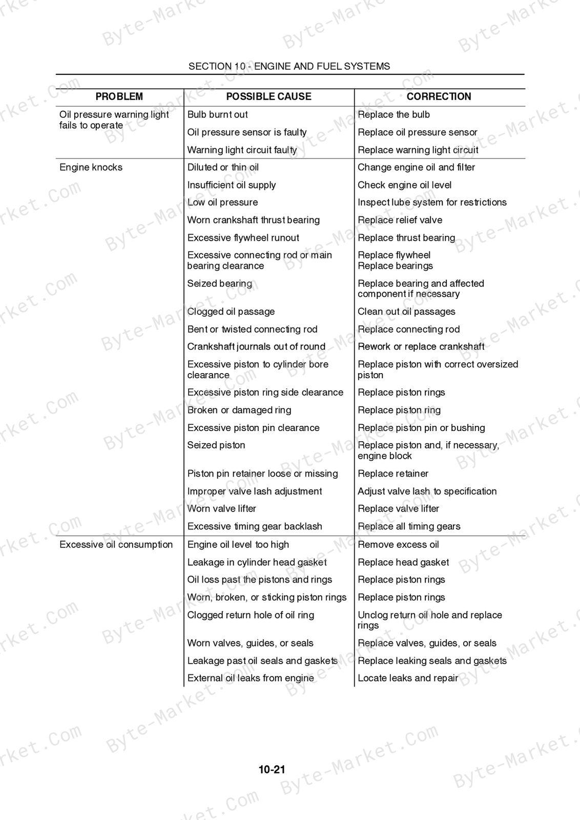
- Troubleshooting — p. 57
- Compression Test — p. 61
- Engine Overhaul — p. 63
- Engine Removal — p. 63
- Engine Disassembly — p. 68
- Oil Pan and Pick-up Removal — p. 75
- Connecting Rods, Bearings, and Piston Removal — p. 76
- Cylinder Head — p. 78
- Cylinder Block — p. 85
- Pistons, Piston Rings, and Connecting Rods - Disassembly and Inspection — p. 86
- Pistons, Rings, and Connecting Rod Assembly — p. 93
- Oil Pump Port Block — p. 101
- Camshaft and Timing Gears — p. 102
- Flywheel — p. 105
- Timing Gear Housing — p. 105
- Engine Assembly — p. 106
- Oil Pick-up and Pan Installation — p. 108
- Oil Pump, Idler Gear, and Injection Timing — p. 109
- Cylinder Head Assembly — p. 110
- Engine Installation — p. 114
- Lubrication System Specifications — p. 120
- Engine Lubrication System — p. 121
- Oil Filter — p. 124
- Oil Pump — p. 124
- Engine Oil Pressure Check — p. 126
- Oil Consumption — p. 127
- Cooling System — p. 128
- Description of Operation — p. 129
- Maintenance — p. 131
- Coolant — p. 131
- Radiator Cap — p. 131
- Cooling System Overhaul — p. 134
- Radiator — p. 134
- Water Pump — p. 139
- Thermostat — p. 145
- Fuel System — p. 148
- Special Tools — p. 149
- Description of Operation — p. 150
- Injection Pump (MC22) — p. 150
- Injection Pump (MC28 and MC35) — p. 156
- Pumping Elements — p. 161
- Delivery Valves — p. 163
- Governor — p. 165
- Fuel Injectors — p. 167
- Fuel System Repair — p. 174
- Governor Disassembly — p. 183
- Fuel Injectors — p. 191
-
- SECTION 25 - FOUR WHEEL DRIVE REAR AXLE — p. 194
- Chapter 1 -- Four Wheel Drive Rear Axle — p. 194
- Specifications — p. 195
- Description of Operation — p. 197
- Troubleshooting — p. 203
- Overhaul — p. 205
- Disassembly - Drop Box — p. 206
- Assembly - Drop Box — p. 213
- Chapter 1 -- Four Wheel Drive Rear Axle — p. 194
- SECTION 27 - DIFFERENTIAL, AXLES — p. 234
-
Chapter 1 - Differential, Axles — p. 234 — expand topics
- Specifications — p. 235
- Metric Bolt Torque Specifications — p. 236
- Special Tools — p. 237
- Description of Operation — p. 238
- Power Flow - Range Gear — p. 241
- Overhaul — p. 243
- Transaxle — p. 243
- Rear Transmission — p. 253
- Front Transmission — p. 270
- Axle — p. 276
- Differential — p. 286
- Drive Pinion Shaft — p. 293
- Differential Lock — p. 297
- Calibration — p. 298
-
- SECTION 29 - HYDROSTATIC DRIVE SYSTEM — p. 300
-
Chapter 1 - Hydrostatic Drive System — p. 300 — expand topics
- Specifications — p. 301
- Metric Bolt Torque Specifications — p. 302
- Special Tools — p. 303
- Description of Operation — p. 304
- Hydraulic Fluid Flow - Neutral Position — p. 307
- Hydraulic Fluid Flow - Forward Position — p. 308
- Hydraulic Fluid Flow - Reverse Position — p. 309
- Hydrostatic Transmission Filter — p. 310
- Pressure Testing — p. 313
- Hydrostatic Transmission Adjustment — p. 357
- Directional Control Pedal Linkage Adjustment — p. 360
-
- SECTION 31- PTO — p. 364
- Chapter 1 - PTO — p. 364
- Specifications — p. 365
- Metric Bolt Torque Specifications — p. 366
- Special Tools — p. 366
- Description of Operation — p. 367
- Chapter 1 - PTO — p. 364
- SECTION 33 – BRAKES — p. 392
- Chapter 1 - Brakes — p. 392
- Specifications — p. 393
- Metric Bolt Torque Specifications — p. 394
- Description of Operation — p. 395
- Brake Operation — p. 396
- Parking Brake — p. 397
- Troubleshooting — p. 398
- Overhaul - Removal — p. 399
- Parking Brake Adjustment — p. 406
- Chapter 1 - Brakes — p. 392
- SECTION 35 - HYDRAULIC SYSTEM — p. 408
-
Chapter 1 - Hydraulic System — p. 408 — expand topics
- Specifications — p. 409
- Special Tools — p. 410
- Description of Operation — p. 411
- Hydraulic Fluid Filter — p. 413
- Lift Control Valve — p. 414
- Fluid Flow - Neutral Position — p. 415
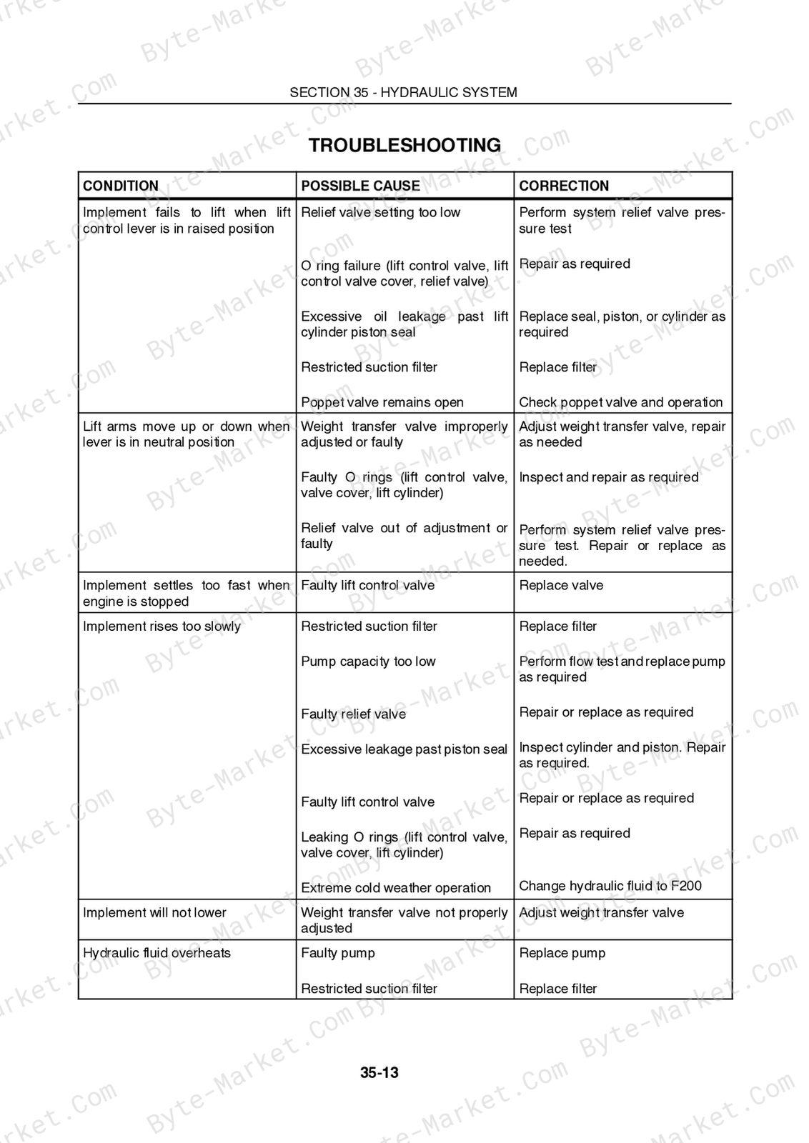
- Troubleshooting — p. 420
- Pressure Testing — p. 421
- Hydraulic Lift Cylinders — p. 424
- Hydraulic Lift Control Valve — p. 434
- Weight Transfer Valve — p. 441
- Hydraulic System Relief Valve — p. 444
- Hydraulic System Restrictor Valve — p. 448
- Lift Arms — p. 450
- Hydraulic Fluid Cooler — p. 453
- Hydraulic Pump — p. 455
- Remote Valves — p. 462
- Remote Valve Operation — p. 463
-
- SECTION 41 – STEERING — p. 476
-
Chapter 1 - Steering — p. 476 — expand topics
- Specifications — p. 477
- Metric Bolt Torque Specifications — p. 478
- Special Tools — p. 479
- Description of Operation — p. 480
- Power Steering System Components — p. 481
- Hydrostatic Transmission Charge Pump — p. 483
- Steering Column and Wheel — p. 484
- Oil Flow - Neutral Operation — p. 485
- Troubleshooting — p. 489
- Pressure Testing — p. 491
- Steering Cylinder Test — p. 494
- Lubrication — p. 496
- Overhaul — p. 497
- Power Steering Motor — p. 497
- Steering Cylinder — p. 512
- Steering Column Removal and Disassembly — p. 518
-
- SECTION 44 - TWO-WHEEL DRIVE REAR AXLE — p. 526
- Chapter 1 - Two-Wheel Drive Rear Axle — p. 526
- Specifications — p. 527
- Metric Bolt Torque Specifications — p. 528
- Description of Operation — p. 529
- Troubleshooting — p. 530
- 2WD Rear Axle Overhaul — p. 531
- Chapter 2 - Wheels and Tires — p. 540
- Wheel Tread Settings — p. 541
- Tractor Weighting — p. 543
- Tire Inflation vs. Permissible Load — p. 545
- Wheel Bolt Torque — p. 545
- Chapter 1 - Two-Wheel Drive Rear Axle — p. 526
- SECTION 55 – ELECTRICAL — p. 546
-
Chapter 1 - Electrical — p. 546 — expand topics
- Introduction — p. 548
- Description — p. 548
- Main Ground Locations — p. 551
- Electrical System Components - Description and Testing — p. 552
- Battery — p. 552
- Fusible Link — p. 554
- Fuse Block — p. 555
- Key Switch — p. 556
- Light Switch — p. 561
- Headlight — p. 563
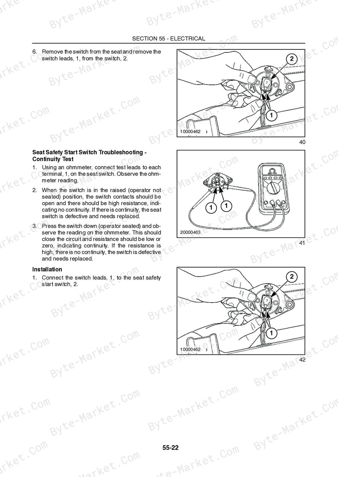
- Seat Safety Start Switch — p. 565
- PTO Safety Start Switch — p. 568
- Hydrostatic Transmission Safety Start Switch — p. 571
- Parking Brake Safety Start Switch — p. 575
- Master Brake Safety Start Switch — p. 578
- Relays — p. 581
- Relay Operation Testing — p. 585
- Diodes — p. 588
- Glow Plug Indicator Light Timer — p. 589
- Seat Safety Switch Timer — p. 590
- Engine Oil Pressure and Overheat Warning Alarm — p. 592
- Engine Glow Plugs — p. 593
- Engine Oil Pressure Switch — p. 597
- Engine Coolant Temperature Switch — p. 601
- Engine Coolant Temperature Sending Unit — p. 604
- Air Filter Restriction Switch — p. 607
- Fuel Shutoff Solenoid — p. 609
- Fuel Level Sending Unit — p. 611
- Electric Fuel Pump — p. 614
- Auxiliary Power Outlet — p. 616
- Electric Cruise Control Switch — p. 618
- Individual Circuit Schematics — p. 625
- Air Filter Restriction Warning Circuit — p. 658
- Instrument Panel - Component Operation and Servicing — p. 674
- Alternator Specifications - MC 22 — p. 682
- Charging System for MC 22 Tractors — p. 683
- Alternator Component Construction — p. 684
- Alternator Troubleshooting - MC 22 — p. 686
- Preliminary Alternator Tests — p. 688
- Alternator Removal — p. 690
- Alternator Disassembly — p. 691
- Alternator Component Testing and Inspection — p. 697
- Alternator Bench Check — p. 706
- Alternator Specifications - MC 28 and MC 35 — p. 707
- Charging System for MC 28 and MC 35 Tractors — p. 708
- Preliminary Alternator Tests — p. 713
- Alternator Component Testing and Inspection — p. 719
- Alternator Bench Check — p. 728
- Starting System - MC 22 — p. 731
- Components — p. 731
- Electrical Testing — p. 746
- No Load Test — p. 756
- Starting System - MC 28 — p. 759
- Components — p. 759
- Electrical Testing — p. 771
- No Load Test — p. 777
- Starting System - MC 35 — p. 781
- Components — p. 781
- Electrical Testing — p. 797
- No Load Test — p. 808
-
- SECTION 90 - PLATFORM — p. 810
- Chapter 1 - Platform — p. 810
- Engine Cover — p. 811
- Fenders — p. 812
- Seat Belt / Seat/ Seat Deck — p. 815
- Roll Over Protective Structure (ROPS) — p. 818
- Foldable ROPS — p. 819
- Fuel Tank — p. 822
- Operator Deck — p. 824
- Chapter 1 - Platform — p. 810
Technical reference
Reference tables include wear limits for service specifications, limits, adjustment and repair reference data. Use the values and conditions in the PDF for the applicable model and procedure.
- Service limits and settings: wear limits.
Delivery
This manual is supplied as a digital PDF file and is available for instant download after purchase. No physical media is shipped.
References
New Holland Service Manual for Commercial Mower, document code 604.55.081.00, PDF edition.


No questions found.