
New Holland Service Manual
New Holland TC5070 Service Manual
Document number 84465927 · English PDF edition · 708 pages
About this manual
New Holland published this Service Manual for TC5070. It is intended for maintenance, source-supported service, and source-supported repair, where those subjects appear in the source publication.
Use the Manual Contents below to check that the exact maintenance, inspection, service, or repair procedure you need is included in this publication.
Manual details
- Manufacturer
- New Holland
- Manual type
- Service Manual
- Models
- TC5070
- Applicability
- Market/version scope: TC5070 combine line and versions in Brazil
- Document number
- 84465927
- Publication year
- 2010
- Publication date
- 07.2010
- Language
- English
- Page count
- 708
Product highlights
Electrical systems
The manual includes wiring diagrams and electrical troubleshooting.
Hydraulic systems
The manual includes hydraulic circuit diagrams and hydraulic valve-adjustment material.
Special tools
A special-tools section is included.
Maintenance
The manual includes a maintenance schedule.
Manual contents
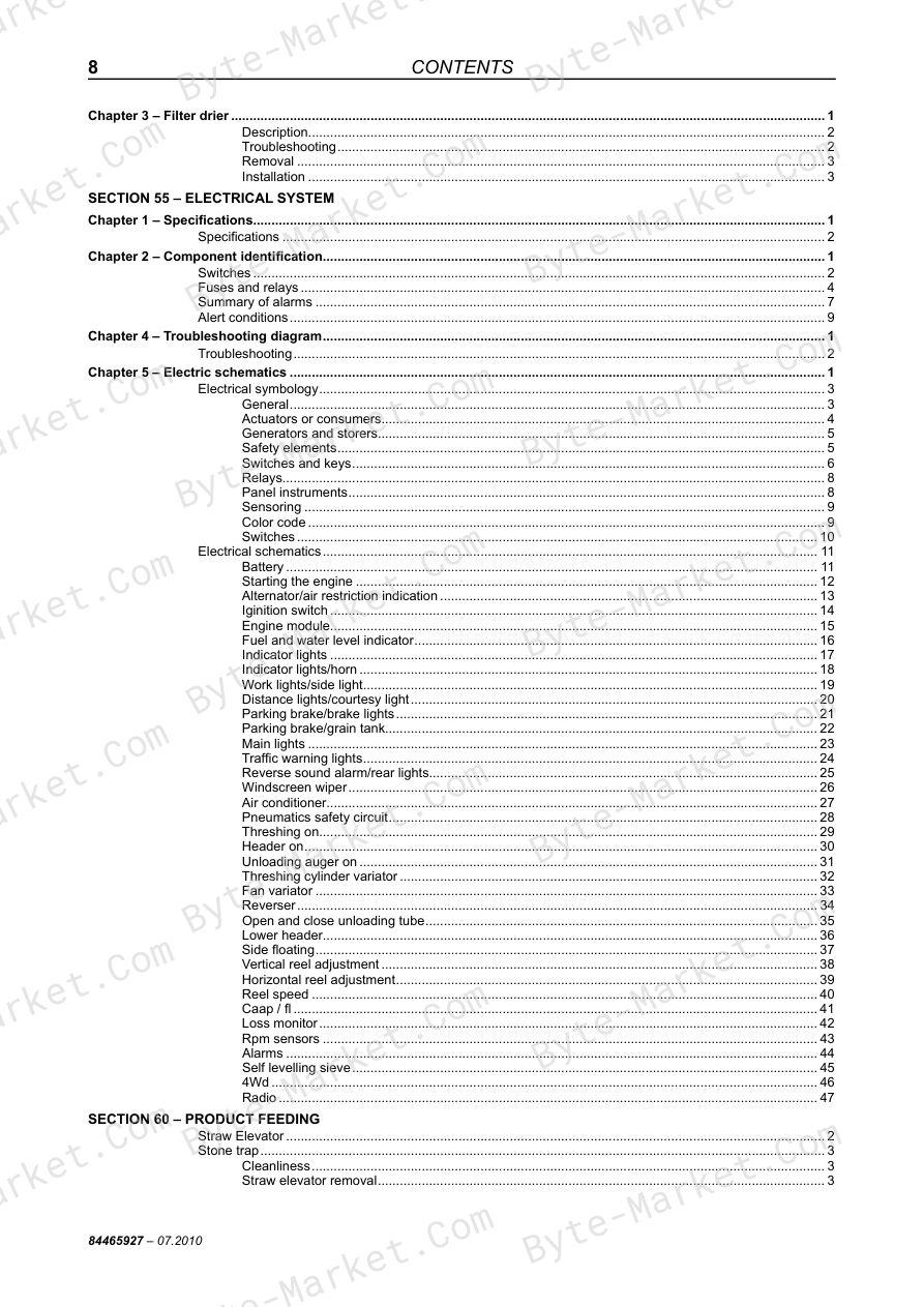
Use these source headings to locate the task or system you need in the PDF.
- Section 00 – GENERAL INFORMATION — p. 14
- INTRODUCTION — p. 15
- COMBINE CARE — p. 16
- END-OF-SEASON SERVICE — p. 16
- MAINTENANCE BETWEEN SEASONS — p. 17
- ACQUISITION OF REPLACEMENT PARTS — p. 18
- SERVICING BEFORE THE SEASON — p. 18
- SAFETY NORMS — p. 20
- BEFORE OPERATING THE MACHINE — p. 20
- Starting — p. 20
- Operating the machine — p. 20
- TOWING THE HARVESTER — p. 21
- TRANSPORTING THE MACHINE — p. 21
- Stopping the machine — p. 21
- Adjusting the machine — p. 21
- SPECIAL CARE — p. 22
- KEYS — p. 22
- BELTS — p. 22
- CHAINS — p. 22
- BEARINGS — p. 22
- PRODUCT IDENTIFICATION — p. 23
- CONVERSION TABLE — p. 25
- Symbols — p. 25
- CONVERSIONS — p. 25
- TORQUE CHART — p. 26
- Metric — p. 26
- BASIC OPERATION — p. 29
- DASHBOARD — p. 30
- LOSS CONTROL (A) — p. 31
- General Module (B) — p. 32
- Instruments — p. 32
- Digital Display — p. 32
- CALIBRATION KEYS — p. 33
- Browsing keys — p. 33
- DISPLAY PROGRAMMING — p. 34
- DASHBOARD — p. 38
- DRIVE KEYS [hydrostatic transmission] — p. 40
- Function of switches — p. 40
- Complementary Switches and Controls — p. 41
- CONTROLS [hydrostatic transmission] — p. 42
- Multifunction Lever — p. 43
- Combine forward speed adjustment lever — p. 43
- DRIVE KEYS [mechanical transmission] — p. 44
- Function of switches — p. 44
- CONTROLS [mechanical transmission] — p. 46
- Lubricant specifications — p. 49
- MAINTENANCE AND LUBRICATION SCHEMATICS — p. 50
- Lubricating nipples and intervals — p. 52
- ADJUSTMENTS AND MAINTENANCE — p. 61
- Drive belts and chains (Left-hand side) — p. 61
- Drive variator adjustment — p. 65
- Variator Support Position — p. 66
- Variator Alignment — p. 66
- DRIVE BELTS AND CHAINS [right-hand side] — p. 68
- Checking and Adjusting the Variator — p. 71
- Fan variator adjustment — p. 73
- STEERING AXLE — p. 74
- Rear Wheel Toe-In Adjustment — p. 74
- Adjusting the Rear Wheels Turning Angle Limiters — p. 75
- Service Routine — p. 76
- Fuel level — p. 76
- Coolant level — p. 76
- Lubricant oil level — p. 77
- Periodic maintenance — p. 77
- Fuel reservoir — p. 77
- Fuel Pre-Filter — p. 77
- Fuel filters — p. 78
- Cooling system — p. 78
- Cleaning the rotating screen — p. 80
- Cleaning the radiator — p. 80
- Air intake system — p. 81
- Cleaning the pre-filter — p. 81
- Cleaning the primary filtering element — p. 81
- Element replacement — p. 82
- Lubricant Oil Level — p. 83
- Oil Change — p. 83
- Oil sump ventilation system — p. 84
- Valve Clearances — p. 84
- Head bolts — p. 84
- Precautions with the turbocharger — p. 84
- AIR CONDITIONER — p. 85
- Cab Air Filter — p. 85
- Condenser — p. 85
- Evaporator — p. 85
- Coolant charge and change — p. 85
- Charge — p. 86
- Coolant inspection and replacement — p. 86
- Coolant hoses — p. 86
- Safety Precautions for Operating on Hills — p. 90
- COMBINE ADJUSTMENTS — p. 91
- MEASURING GRAIN LOSS — p. 94
- Simplified Procedure — p. 94
- Example — p. 94
- Specific Measurement Procedure — p. 94
- LOSSES FROM THE MACHINE — p. 97
- troubleshooting — p. 98
- Section 10 – ENGINE — p. 103
- SPECIFICATIONS — p. 105
- ASSEMBLY DIMENSIONS — p. 106
- TIGHTENING TORQUES — p. 108
- Special tools — p. 113
- Engine Cold Starting — p. 113
- Cooling System — p. 114
- Lubrication System — p. 115
- Fault diagnosis — p. 116
- Installing the engine on the trestle — p. 119
- Removing the turbocharger — p. 121
- ENGINE DISASSEMBLY — p. 121
- Valve disassembly — p. 126
- Replacing the cylinder block bushes — p. 132
- Installing tappets and camshaft — p. 133
- Assembling the engine — p. 133
- Installing oil sparger nozzles — p. 134
- Installing the main bearings — p. 134
- Installing the main bearing covers — p. 135
- Assembling the piston/link conrod set — p. 136
- Piston/link conrod coupling — p. 136
- Installing the rings — p. 136
- Installing the piston/link conrod sets on the cylinder sleeves — p. 137
- Diagram for installing the piston/link conrod sets on the cylinder sleeves — p. 137
- Camshaft sychronism — p. 138
- Installing the synchronism gear box — p. 139
- Installing the water pump — p. 140
- Installing the oil pump — p. 140
- Installing the engine sump sealing gasket — p. 142
- Installing the engine oil sump — p. 142
- Installing the engine flywheel — p. 142
- Installing the oil filter head — p. 143
- Installing the alternator — p. 144
- Installing the cylinder head — p. 145
- Installing the rocker arm sets — p. 146
- Installing the injection nozzles — p. 147
- Installing the valve cover — p. 148
- Installing the exhaust manifold — p. 148
- Installing the thermostat — p. 148
- Installing the fan pulley — p. 149
- Installing the alternator belt — p. 149
- Installing the intake manifold — p. 149
- Installing the pressure tube — p. 151
- Installing the turbocharger — p. 153
- Completing the engine — p. 153
- checking and measuring — p. 155
- Cylinder block — p. 155
- Checking the head contact surface — p. 156
- Tappets — p. 156
- Crankshaft — p. 157
- Dimensions of main trunnions and the link conrod — p. 157
- Main bushings clearance — p. 159
- Checking the crankshaft thrust ring clearance — p. 160
- Checking the camshaft raising and alignment — p. 161
- Bushes — p. 161
- Camshaft — p. 161
- Piston/Link Conrod Set — p. 162
- Pistons — p. 164
- Measuring piston diameter — p. 164
- Piston pins — p. 164
- Conditions for correct coupling of the piston pin — p. 164
- Bushes — p. 166
- Torsion check — p. 167
- Warp check — p. 167
- Link conrod bushing clearance — p. 168
- Piston projection check — p. 169
- Cylinder head — p. 170
- Cylinder head tightness check — p. 170
- Checking the cylinder head contact surface — p. 170
- Valves — p. 171
- Valve decarbonization, checking and overhauling — p. 171
- Checking the clearance between the valve rod and guide and centering the valve — p. 171
- Valve guides — p. 172
- Valve seats — p. 172
- Valve springs — p. 173
- Rocker arm shaft — p. 173
- Valve clearance adjustment — p. 174
- Procedure to remove the injection pump — p. 175
- ROTARY injection pump removal, installation and synchronization — p. 175
- Procedure to alter the injection pump static point arranged on a bench — p. 180
- Procedure to assemble the injection pump on the engine — p. 182
- Cold start device operating test (kksb) — p. 184
- Deaeration (bleeding) the fuel system — p. 187
- Checking injection pump synchronism — p. 187
- Section 21 – TRANSMISSION — p. 191
- Gearbox 3MD-35 — p. 192
- Construction and Operation — p. 192
- List of Lubricants TE-ML.07 — p. 192
- GEARBOX – TC5070 MECHANICAL — p. 193
- GEARBOX – TC5070 HYDRO — p. 195
- SPECIFICATIONS — p. 197
- Technical data and adjustment values — p. 197
- Temperature for Assembly — p. 197
- Tightening Torques — p. 197
- Disassembly Sequence — p. 198
- Cover — p. 198
- Coupling and Inversion Carcass — p. 199
- Reverse Shaft — p. 201
- Idler Shaft — p. 202
- Drive Shaft — p. 202
- Differential Cover — p. 203
- Differential — p. 203
- Differential — p. 204
- Gearbox Carcass — p. 205
- Assembly Sequence — p. 205
- Differential — p. 205
- Gearbox Carcass — p. 207
- Differential Cover — p. 208
- Outer measurement of the differential cover (left-hand side) — p. 209
- Inner measurement of the differential cover (left-hand side) — p. 209
- Adjusting Differential Clearance — p. 210
- Measurement between the bearing and the carcass (left-hand side) — p. 210
- Drive Shaft — p. 213
- Idler Shaft — p. 216
- Reverse Shaft — p. 218
- Cover Adjustment — p. 218
- Fork assembly — p. 219
- Fork Setting — p. 220
- Adjusting the Variator Shaft Bearing Axial Clearance — p. 222
- Measurement “A” — p. 222
- Measurement “B” — p. 222
- Adjusting the idler shaft bearing axial clearance — p. 223
- Measurement “A” — p. 223
- Measurement “B” — p. 223
- Measurement “C” — p. 224
- Measurement “D” — p. 224
- Shift Cover — p. 225
- Gearbox 3MD-35 — p. 192
- Section 22 – Drive clutch — p. 227
- DRIVE CLUTCH [mechanical transmission] — p. 228
- Bleeding the clutch hydraulic command — p. 228
- REAR WHEEL TOE-IN — p. 229
- Rear axle pivot positions — p. 229
- DRIVE CLUTCH [mechanical transmission] — p. 228
- Section 23 – Drive variator — p. 231
- Belt Tension Adjustment — p. 232
- Variator Adjustment — p. 232
- Variator Support Position — p. 233
- Variator Alignment — p. 233
- Vertical Alignment — p. 233
- Horizontal Alignment — p. 233
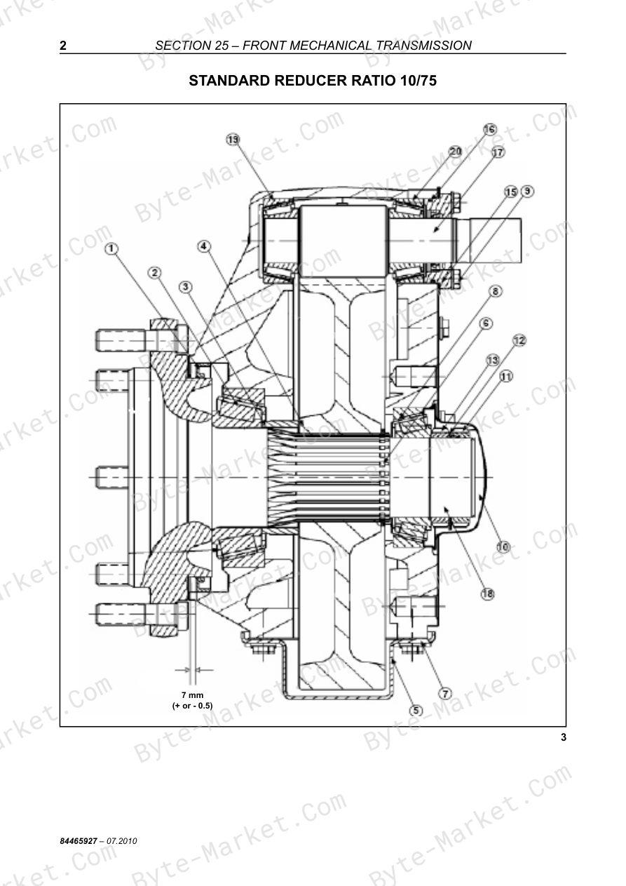
- Section 25 – FRONT MECHANICAL TRANSMISSION — p. 235
- STANDARD REDUCER ratio 10/75 — p. 236
- Disassembly — p. 237
- Assembly — p. 237
- WHEEL BOLT – REPLACEMENT — p. 238
- FINAL DRIVE – Removal/Installation — p. 239
- FINAL DRIVE – Disassembly/Assembly — p. 241
- Disassembly — p. 243
- Assembly — p. 243
- Specifications — p. 247
- Technical Data and Adjustment Values — p. 247
- Tightening Torques — p. 247
- Rice Drive Ratio 10/75 — p. 248
- Disassembly — p. 249
- Assembly — p. 249
- STANDARD REDUCER ratio 10/75 — p. 236
- Section 33 – BRAKES — p. 250
- BRAKE PAD REPLACEMENT — p. 251
- Removal — p. 251
- Installation — p. 251
- Brake shoe disasembly and assembly — p. 252
- Brake disk disassembly — p. 252
- Brake disk assembly — p. 252
- Brake shoe assembly — p. 252
- BRAKES — p. 255
- SERVICE BRAKE ADJUSTMENT — p. 255
- PARKING BRAKE ADJUSTMENT — p. 255
- BLEEDING THE CONNECTION BETWEEN THE TWO MAIN CYLINDERS — p. 256
- BLEEDING THE RIGHT-HAND CIRCUIT — p. 256
- BRAKE PAD REPLACEMENT — p. 251
- Section 35 – hydraulic system — p. 258
- specifications — p. 259
- FLOW RATE REDUCERS — p. 259
- HYDRAULIC PUMP — p. 260
- Characteristics — p. 260
- HYDRAULIC CYLINDERS — p. 260
- HYDRAULIC SCHEMATICS – TC5070 Mechanical — p. 261
- HYDRAULIC SCHEMATICS – TC5070 Hydro — p. 262
- HYDRAULIC SYSTEM — p. 263
- TC5070 Combine [mechanical transmission] — p. 263
- TC5070 Combine [hydrostatic transmission] — p. 264
- HYDRAULIC CONTROL – FULL SET — p. 265
- HYDRAULIC CYLINDERS — p. 266
- Disassembly/Assembly to change repair kit — p. 266
- HYDROPNEUMATIC COMPENSATORS AND CYLINDERS — p. 267
- Hydropneumatic compensators — p. 267
- REVERSER HYDRAULIC MOTOR REMOVAL, INSTALLATION, DISASSEMBLY, INSPECTION AND ASSEMBLY — p. 269
- Preliminary Preparation for Disassembly — p. 269
- Removal and Installation — p. 270
- Removal — p. 270
- Installation — p. 273
- Disassembly and Inspection — p. 275
- Assembly — p. 282
- Final check — p. 291
- Rotor assembly — p. 292
- One Part Stator — p. 292
- Practical maintenance tips for the HYDRAULIC MOTOR – PARKER — p. 294
- SPECIAL TOOLS — p. 297
- SPECIFICATIONS — p. 297
- STEERING VALVE — p. 298
- Characteristics — p. 298
- Removal — p. 299
- Installation — p. 300
- Disassembly — p. 300
- Assembly — p. 305
- PUMP GROUP — p. 309
- Main hydraulic pump — p. 310
- Hydraulic pump (steering circuit) — p. 311
- Hydraulic pump (side floating circuit) — p. 312
- GENERAL PRINCIPALS — p. 355
- Circuit — p. 355
- Description and operation of the variable yield pump — p. 355
- Description and operation of the hydrostatic motor — p. 357
- Operation of the fixed displacement motor — p. 357
- Rotating direction — p. 357
- HYDROSTATIC TRANSMISSION — p. 358
- Hydrostatic pump (cut view) — p. 358
- Hydrostatic motor (cut view) — p. 359
- HYDROSTATIC SYSTEM (TC5070 Hydrostatic transmission) — p. 360
- Technical Data — p. 360
- Hydrostatic system oil change and refilling — p. 360
- Filling and bleeding the hydrostatic system — p. 360
- Hydrostatic System mechanical adjsutments — p. 362
- Adjust the control cable — p. 362
- Belt tension adjustment — p. 362
- HYDROSTATIC CIRCUIT AND COMPONENTS — p. 363
- MULTIFUNCTION VALVE — p. 366
- Disassembling and assembling the main components — p. 369
- Troubleshooting and measurement points — p. 369
- Hydrostatic pump — p. 369
- Precautions — p. 369
- Retainer and shaft replacement — p. 369
- Replacing the charge pressure relief valve — p. 371
- CHARGE PUMP — p. 372
- Replacing the charge pump — p. 372
- Disassembly — p. 372
- Assembly — p. 374
- Replacing the control valve — p. 375
- Multifunction valves inspection and adjustment — p. 376
- Pressure valve adjusment — p. 376
- Bypass valves — p. 376
- Hydrostatic motor — p. 377
- Replacing the shaft and retainer — p. 377
- Replacing the charge pressure relief valve — p. 378
- Replacing the shuttle valve — p. 378
- HYDROSTATIC CIRCUIT – AUXILIARY DRIVE — p. 315
- How it Works — p. 316
- Initial Yield Position (Drive system activated) — p. 316
- Maximum yield position — p. 317
- Low neutral position — p. 317
- Discharge position — p. 317
- High Neutral Position — p. 318
- Wheel motor power distribution — p. 318
- MAINTENANCE PROCEDURES — p. 320
- Wheel-motor cut view — p. 320
- Wheel-motor component — p. 322
- SHAFTS/GASKETS AND BEARINGS — p. 324
- Disassembly — p. 324
- Assembly — p. 330
- Block and piston set — p. 343
- Disassembly — p. 343
- Assembly — p. 347
- DISTRIBUTOR (VALVE BLOCK) AND DISTRIBUTION GASKETS — p. 348
- Disassembly — p. 348
- Assembly — p. 350
- ACCUMULATOR — p. 352
- Description and operation — p. 352
- Disassembling the accumulator — p. 352
- Information to replace the accumulator — p. 353
- Installing the accumulator — p. 353
- specifications — p. 259
- WHEEL MOTOR MAINTENANCE — p. 401
- Preventive Maintenance and Precautions — p. 401
- General Recommendations — p. 401
- TROUBLESHOOTING — p. 400
- Wheel Motors — p. 400
- WHEEL MOTOR OPERATION — p. 399
- General Information — p. 399
- Description — p. 399
- DISASSEMBLY AND ASSEMBLY OF THE REAR AXLE — p. 398
- Disassembly — p. 398
- Assembly — p. 398
- REAR AXLE MAINTENANCE — p. 396
- Basic maintenance requirements — p. 396
- Every 100 hours of Machine Operation — p. 396
- Cross-section — p. 396
- Every 100 hours of Machine Operation — p. 397
- STARTING PROCEDURE — p. 395
- TEST GAUGE LOCATIONS — p. 392
- Test Procedure Nº 2 — p. 392
- Test Procedure Nº 3 — p. 393
- TESTING PROCEDURE — p. 390
- Test Procedure Nº 1 — p. 390
- Test Pressures versus Mode of Machine Operation — p. 391
- Troubleshooting — p. 388
- Fluidrive Rear Drive Systems — p. 388
- GENERAL INFORMATION — p. 381
- Safety Measures — p. 381
- Operation of the Fluidrive System — p. 381
- Troubleshooting the Hydraulic Circuit — p. 403
- Steering — p. 403
- Header — p. 404
- Reel — p. 405
- Unloading Tube — p. 405
- Drive Variator — p. 405
- Lateral Flotation — p. 406
- Reverser — p. 406
- Others — p. 406
- Section 36 – Pneumatic System — p. 408
- SYMBOLS USED — p. 409
- HYDRAULIC CONTROL ROD ACTUATOR CYLINDER — p. 415
- Installation of the sintered filter — p. 415
- Installation kit — p. 415
- MICRO SOLENOID VALVE 3/2 PORTS – NC (Normally Closed) — p. 416
- TECHNICAL DATA — p. 416
- PNEUMATIC COMPONENTS — p. 417
- Solenoid Valve — p. 417
- Rotary Joint — p. 417
- Drier Filter — p. 417
- Pneumatic Cylinder — p. 417
- Reverser Pneumatic Cylinder — p. 418
- Ball Valve — p. 418
- PNEUMATIC EQUIPMENT — p. 419
- Selector Valve (“OR” Element) — p. 419
- Ball Valve — p. 419
- Reverser Control Valve — p. 419
- PRESSURE REGULATOR — p. 420
- Schematic — p. 420
- Lubricator — p. 421
- PNEUMATIC SYSTEM — p. 422
- PNEUMATIC SCHEMATIC — p. 423
- Pneumatic clutch — p. 425
- Removing the pneumatic clutch — p. 425
- Disassembling the pneumatic clutch — p. 425
- Assembling the pneumatic clutch — p. 426
- Disassembling the pneumatic clutch — p. 434
- Assembling the pneumatic clutch — p. 437
- Section 48 ‒ TRACKS — p. 440
- Specifications — p. 441
- Assembly Torques — p. 442
- TRACKS — p. 443
- New Holland Tracks for Rice Harvesters — p. 444
- Introduction — p. 445
- Front Axle — p. 445
- Rolling material — p. 445
- Straw elevator — p. 445
- Drive Wheels — p. 447
- Shoes — p. 447
- Attaching to the Harvester — p. 448
- Rear Tires — p. 449
- MAINTENANCE — p. 449
- TRACK INSTALLATION — p. 450
- TOWING INSTRUCTIONS FOR HARVESTERS EQUIPPED WITH TRACKS — p. 454
- Section 50 ‒ CLIMATE CONTROL/AIR CONDITIONER — p. 456
- Introduction — p. 457
- Correct use of the air-conditioning system — p. 458
- Storage maintenance — p. 458
- AIR CONDITIONING CIRCUIT — p. 459
- Location of the A/C components — p. 460
- Filter-drier (5) — p. 460
- Condenser (4) — p. 460
- Evaporator (7) — p. 460
- Compressor (1) — p. 460
- A/C CYCLE — p. 461
- Air-conditioning process — p. 461
- Lubricants — p. 462
- Operation — p. 462
- COOLANT — p. 463
- Refrigerant recovery procedure — p. 463
- Washing — p. 464
- Recharge/Refilling — p. 464
- Use of a manifold gauge set — p. 464
- Checking refrigerant for excess air — p. 465
- Containers for the storage of recycled refrigerant — p. 466
- Transfer of refrigerant — p. 466
- Disposal of empty or near empty disposable containers — p. 467
- Applicable SAE standards — p. 467
- Related SAE standards — p. 467
- TESTING AND TROUBLESHOOTING, GENERAL — p. 468
- General safety and service precautions — p. 468
- Check for leaks — p. 469
- Cleanliness — p. 469
- Refilling — p. 469
- Contaminants — p. 470
- Prevent mixing of service equipment — p. 470
- PRELIMINARY TROUBLESHOOTING AND TESTING — p. 471
- Operational checks ‒ Heating — p. 471
- Operational checks ‒ A/C — p. 471
- PRELIMINARY DIAGNOSTICS CHART — p. 472
- TEST PROCEDURE ‒ STABILIZING THE SYSTEM TEST PORTS — p. 473
- A/C SYSTEM PERFORMANCE TEST AND DIAGNOSTICS CHART — p. 474
- GAUGE READINGS AND INTERPRETATIONS — p. 478
- Description — p. 491
- Removal — p. 491
- Installation — p. 492
- Description — p. 495
- Troubleshooting — p. 495
- Removal — p. 496
- Installation — p. 496
- Introduction — p. 457
- Section 55 ‒ ELECTRICAL SYSTEM — p. 498
- SPECIFICATIONS — p. 499
- SWITCHES — p. 501
- Fuses and relays — p. 503
- SUMMARY OF ALARMS — p. 506
- ALERT CONDITIONS — p. 508
- TROUBLESHOOTING — p. 511
- ELECTRICAL SYMBOLOGY — p. 518
- General — p. 518
- Actuators or Consumers — p. 519
- Generators and Storers — p. 520
- Safety Elements — p. 520
- Switches and Keys — p. 521
- Relays — p. 523
- Panel Instruments — p. 523
- Sensoring — p. 524
- Color code — p. 524
- Switches — p. 525
- ELECTRICAL SCHEMATICS — p. 526
- BATTERY — p. 526
- STARTING THE ENGINE — p. 527
- ALTERNATOR/AIR RESTRICTION INDICATION — p. 528
- IGINITION SWITCH — p. 529
- ENGINE MODULE — p. 530
- FUEL AND WATER LEVEL INDICATOR — p. 531
- INDICATOR LIGHTS — p. 532
- INDICATOR LIGHTS/HORN — p. 533
- WORK LIGHTS/SIDE LIGHT — p. 534
- DISTANCE LIGHTS/COURTESY LIGHT — p. 535
- PARKING BRAKE/BRAKE LIGHTS — p. 536
- PARKING BRAKE/GRAIN TANK — p. 537
- MAIN LIGHTS — p. 538
- TRAFFIC WARNING LIGHTS — p. 539
- REVERSE SOUND ALARM/REAR LIGHTS — p. 540
- WINDSCREEN WIPER — p. 541
- AIR CONDITIONER — p. 542
- PNEUMATICS SAFETY CIRCUIT — p. 543
- THRESHING ON — p. 544
- HEADER ON — p. 545
- UNLOADING AUGER ON — p. 546
- THRESHING CYLINDER VARIATOR — p. 547
- FAN VARIATOR — p. 548
- REVERSER — p. 549
- OPEN AND CLOSE UNLOADING TUBE — p. 550
- LOWER HEADER — p. 551
- SIDE FLOATING — p. 552
- VERTICAL REEL ADJUSTMENT — p. 553
- HORIZONTAL REEL ADJUSTMENT — p. 554
- REEL SPEED — p. 555
- CAAP / FL — p. 556
- LOSS MONITOR — p. 557
- RPM SENSORS — p. 558
- ALARMS — p. 559
- SELF LEVELLING SIEVE — p. 560
- 4WD — p. 561
- RADIO — p. 562
- Section 60 ‒ PRODUCT FEEDING — p. 563
- Straw Elevator — p. 564
- Stone Trap — p. 565
- Cleanliness — p. 565
- Straw elevator removal — p. 565
- STRAW ELEVATOR TRACK CHAINS — p. 566
- Disassembly — p. 566
- Assembly — p. 566
- UPPER SHAFT — p. 567
- Rear straw elevator shaft disassembly — p. 567
- Rear straw elevator shaft assembly — p. 567
- Check the dimensional — p. 568
- Straw elevator slip clutch disassembly — p. 568
- Straw elevator slip clutch disassembly — p. 568
- Section 66 ‒ THRESHING — p. 569
- THRESHING CYLINDER — p. 570
- Disassembly — p. 570
- Assembly — p. 572
- Cylinder balancing — p. 572
- CONCAVES — p. 573
- Concaves available — p. 573
- Adjustments — p. 573
- TEETH CONCAVE OPENING (RICE) — p. 575
- Cylinder and Concave with Teeth — p. 575
- Accessing cylinder and concave — p. 575
- Fine adjustment — p. 576
- Concave replacement — p. 577
- Dust plate — p. 577
- THRESHING CYLINDER — p. 570
- Section 72 ‒ Separation — p. 591
- BEATER — p. 592
- Specifications — p. 592
- Cylinder type — p. 592
- Replacement of the shaft and the bearings — p. 593
- Disassembly — p. 593
- Left side — p. 594
- Assembly — p. 594
- Rotary Separator — p. 596
- Speed adjustments — p. 596
- Procedure to replace the Rotary Separator — p. 597
- Straw Walker — p. 600
- Fitting the crests — p. 600
- Position of the crests — p. 601
- Disassembly of the straw walker and shafts — p. 602
- Disassembly of the straw walker — p. 602
- Disassembly of the straw walker shafts — p. 602
- Rear shaft — p. 602
- Front shaft — p. 602
- Assembly of the straw walker shafts — p. 603
- Rear shaft — p. 603
- Front Axle — p. 604
- Care during shaft installation — p. 604
- Straw walker bearings — p. 604
- GRAIN PAN — p. 606
- Characteristics — p. 606
- Disassembly and assembly of the grain pan and the stone trap — p. 607
- Disassembly of the grain pan — p. 607
- Grain pan installation — p. 607
- BEATER — p. 592
- Section 74 - CLEANING — p. 609
- Fan — p. 610
- CANVAS AIR DEFLECTOR — p. 611
- Replacement of the fan belts — p. 612
- Adjusting — p. 612
- VARIATOR ADJUSTMENT DEVICE — p. 613
- Fan Case — p. 614
- Disassembly — p. 614
- Left Side — p. 614
- Right Side — p. 614
- Assembly — p. 614
- SIEVES — p. 615
- Types of sieve available — p. 615
- Factory sieve adjustment — p. 616
- Removing the sieves — p. 617
- Installation — p. 617
- Installation of the Upper Sieve with Self-Leveling System — p. 618
- Divider crests (1) — p. 619
- With the Self-Leveling System — p. 619
- FITTING THE GRAIN PAN DIVIDERS — p. 620
- Procedure — p. 620
- Section 80 ‒ GRAIN STORAGE — p. 623
- Grain and tailings auger — p. 624
- Disassembly — p. 624
- Assembly — p. 624
- Leveling Auger and Tailings — p. 625
- Tensioning of the grain/tailings elevator conveyor chains — p. 625
- Disassembly of the leveling auger — p. 626
- Assembly — p. 627
- Disassembly of the tailings auger — p. 627
- Assembly of the tailings auger — p. 627
- Unloading tube auger — p. 628
- Disassembly of the unloading tube and auger — p. 628
- Installation of the unloading tube and auger — p. 628
- Adjustment of the unloading auger bearing — p. 629
- Grain and tailings auger — p. 624
- Section 88 ‒ ACCESSORIES — p. 631
- STRAW CHOPPER — p. 632
- SPECIFICATIONS — p. 632
- OPERATION — p. 632
- Deflector — p. 633
- Straw guide vanes — p. 633
- BELT TENSION ADJUSTMENT — p. 634
- Front belt — p. 634
- Correct belt tension — p. 634
- Rear Belt — p. 634
- STRAW CHOPPER SPEED ADJUSTMENT — p. 635
- DEFLECTOR PLATE — p. 635
- TROUBLESHOOTING — p. 636
- STRAW CHOPPER — p. 632
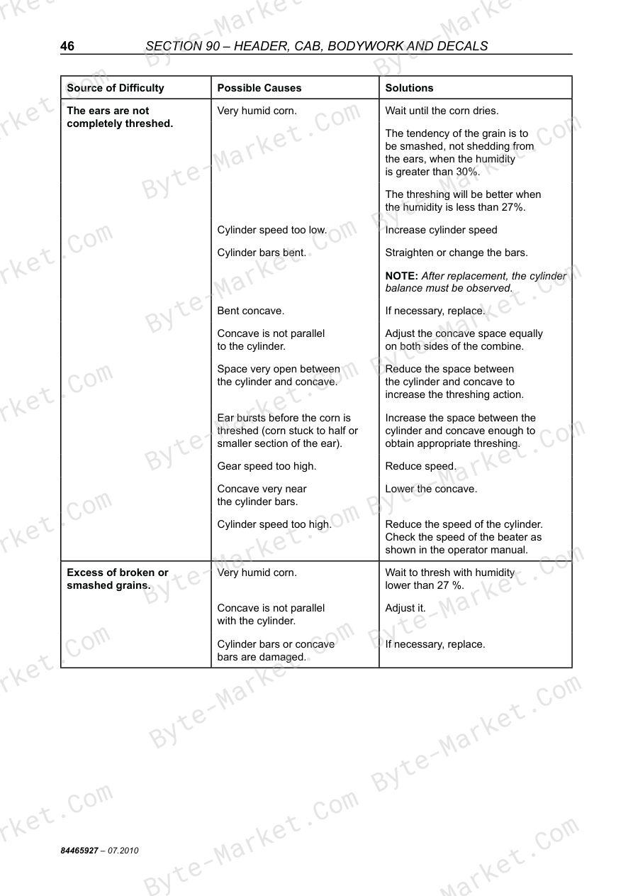
- Section 90 ‒ HEADER, CAB, BODYWORK AND DECALS — p. 639
- CUTTING PLATFORM — p. 640
- Specifications — p. 640
- Cutting platform coupling to the harvester — p. 640
- Uncoupling the cutting platform — p. 642
- Horizontal leveling of the platform — p. 643
- Cutting platform — p. 644
- Flexible System — p. 644
- C.A.A.P. Adjustment/F.3L — p. 645
- CAAP Adjustment — p. 645
- Lateral Flotation Adjustment — p. 645
- Lateral Flotation Components — p. 645
- BLADES AND BLADE BOX — p. 647
- Maintenance of the blade drive box — p. 647
- Oil Level — p. 647
- Oil Change — p. 647
- Knife Replacement — p. 648
- Cutter Bar Alignment — p. 648
- Blade Adjustment — p. 648
- REEL — p. 649
- Leveling — p. 649
- Vertical adjustment — p. 649
- Hydraulic Horizontal Adjustment — p. 649
- Bleeding of the horizontal adjustment hydraulic system — p. 649
- Positioning of fingers — p. 650
- Tensioning the drive chain — p. 650
- FEED AUGER — p. 651
- Drive — p. 651
- Specifications — p. 651
- Flotation adjustment of the auger/retracting fingers — p. 652
- Disassembly — p. 656
- Assembly — p. 658
- CUTTING PLATFORM — p. 640
- TROUBLESHOOTING — p. 704
- ADJUSTMENTS FOR THE CORN HARVEST — p. 703
- FIELD WORK — p. 702
- ADJUSTMENTS AND MAINTENANCE — p. 701
- LUBRICATING NIPPLES — p. 699
- Grease Nipples — p. 699
- Transmission Boxes — p. 700
- Chains — p. 700
- Chain maintenance after the harvest — p. 700
- SERVICE SCHEDULE — p. 698
- LUBRICATION — p. 698
- ROW UNIT SAFETY CLUTCH (TORQUE LIMITER) — p. 693
- DISASSEMBLY OF THE GEARBOX AND ROW UNIT SAFETY CLUTCH — p. 694
- Gearbox — p. 694
- Removal of the gearbox — p. 695
- Stalk rolls ‒ Synchronism of the pullers — p. 695
- Gearbox disassembly — p. 696
- Disassembly and assembly of the safety clutch — p. 696
- Reinstallation of the divider points and dividers — p. 697
- Retaining bracket — p. 697
- Ear saver — p. 697
- ROW UNIT TRANSMISSION BOX — p. 693
- ARTICULATED DIVIDER POINTS — p. 690
- Articulated Points — p. 690
- Drag Plates — p. 690
- Angle of Inclination of Row Units — p. 691
- Vertical Inclination of the Row Units — p. 691
- Row Unit Attachments — p. 691
- Row Unit Drive — p. 692
- SETTING THE DISTANCE BETWEEN ROWS — p. 686
- SETTING THE ROW UNITS — p. 687
- ROW UNIT GUARDS — p. 689
- REVERSER SYSTEM — p. 684
- DECK PLATES — p. 685
- LEFT SHIELD AND DEFLECTOR — p. 685
- ELECTRICAL CONTROL OF THE DECK PLATES — p. 682
- Corn Header Activation — p. 682
- Corn Header Height Control [mechanical transmission] — p. 682
- Corn Header Height Control [hydrostatic transmission] — p. 682
- Adjusting the Distance Between the Deck Plates — p. 683
- FEEDER AUGER AND ROW UNIT DRIVE — p. 680
- Feeder auger with total helix in the center — p. 680
- Feeder auger height — p. 680
- Adjustment of the safety clutch — p. 681
- FEEDER CHAINS — p. 674
- Stalk rolls — p. 675
- Replacement of the stalk rolls — p. 677
- Adjustment of the weed knives and the stalk rolls — p. 678
- Adjustments of the weed knives (Counter knives) — p. 678
- Stalk roll adjustment — p. 679
- PNEUMATIC SYSTEM — p. 673
- SIEVE — p. 672
- FAN — p. 671
- STONE TRAP — p. 670
- CONCAVE — p. 668
- STRAW ELEVATOR ADJUSTMENTS — p. 667
- Straw elevator chain tension — p. 667
- Adjustment of the front axle suspension spring — p. 667
- Chain — p. 667
- STRAW ELEVATOR ‒ HEADER COUPLING — p. 665
- Support Shoes — p. 665
- Coupling the corn header to the combine — p. 666
- HEADER SIZES — p. 663
- REQUIRED PROCEDURES FOR CORN — p. 664
- SPECIFICATIONS — p. 662
- INTRODUCTION — p. 15
- COMBINE CARE — p. 16
- END-OF-SEASON SERVICE — p. 16
- MAINTENANCE BETWEEN SEASONS — p. 17
- SERVICING BEFORE THE SEASON — p. 18
- SAFETY NORMS — p. 20
- TOWING THE HARVESTER — p. 21
- TRANSPORTING THE MACHINE — p. 21
- Stopping the machine — p. 21
- Adjusting the machine — p. 21
- SPECIAL CARE — p. 22
- PRODUCT IDENTIFICATION — p. 23
- CONVERSION TABLE — p. 25
- TORQUE CHART — p. 26
- BASIC OPERATION — p. 29
- DASHBOARD — p. 30
- LOSS CONTROL (A) — p. 31
- General Module (B) — p. 32
- Instruments — p. 32
- CALIBRATION KEYS — p. 33
- DISPLAY PROGRAMMING — p. 34
- DASHBOARD — p. 38
- DRIVE KEYS [hydrostatic transmission] — p. 40
- Function of switches — p. 40
- Complementary Switches and Controls — p. 41
- CONTROLS [hydrostatic transmission] — p. 42
- Multifunction Lever — p. 43
- DRIVE KEYS [mechanical transmission] — p. 44
- Function of switches — p. 44
- CONTROLS [mechanical transmission] — p. 46
- Safety Precautions for Operating on Hills — p. 90
- COMBINE ADJUSTMENTS — p. 91
- MEASURING GRAIN LOSS — p. 94
- Simplified Procedure — p. 94
- Specific Measurement Procedure — p. 94
- LOSSES FROM THE MACHINE — p. 97
- troubleshooting — p. 98
- Gearbox 3MD-35 — p. 192
- GEARBOX ‒ TC5070 MECHANICAL — p. 193
- GEARBOX ‒ TC5070 HYDRO — p. 195
- SPECIFICATIONS — p. 197
- Technical data and adjustment values — p. 197
- Temperature for Assembly — p. 197
- Tightening Torques — p. 197
- Disassembly Sequence — p. 198
- Coupling and Inversion Carcass — p. 199
- Idler Shaft — p. 202
- Drive Shaft — p. 202
- Differential Cover — p. 203
- Differential — p. 203
- Differential — p. 204
- Gearbox Carcass — p. 205
- Assembly Sequence — p. 205
- Differential — p. 205
- Gearbox Carcass — p. 207
- Differential Cover — p. 208
- Drive Shaft — p. 213
- Idler Shaft — p. 216
- Reverse Shaft — p. 218
- Cover Adjustment — p. 218
- Fork assembly — p. 219
- Fork Setting — p. 220
- Adjusting the Variator Shaft Bearing Axial Clearance — p. 222
- Adjusting the idler shaft bearing axial clearance — p. 223
- Shift Cover — p. 225
- DRIVE CLUTCH [mechanical transmission] — p. 228
- Bleeding the clutch hydraulic command — p. 228
- REAR WHEEL TOE-IN — p. 229
- Rear axle pivot positions — p. 229
- Belt Tension Adjustment — p. 232
- Variator Adjustment — p. 232
- Variator Alignment — p. 233
- Specifications — p. 247
- Rice Drive Ratio 10/75 — p. 248
- Disassembly — p. 249
- Assembly — p. 249
- BRAKE PAD REPLACEMENT — p. 251
- Removal — p. 251
- Installation — p. 251
- Brake shoe disasembly and assembly — p. 252
- BRAKES — p. 255
- SERVICE BRAKE ADJUSTMENT — p. 255
- PARKING BRAKE ADJUSTMENT — p. 255
- BLEEDING THE CONNECTION BETWEEN THE TWO MAIN CYLINDERS — p. 256
- BLEEDING THE RIGHT-HAND CIRCUIT — p. 256
- REVERSER HYDRAULIC MOTOR REMOVAL, INSTALLATION, DISASSEMBLY, INSPECTION AND ASSEMBLY — p. 269
- Preliminary Preparation for Disassembly — p. 269
- Removal and Installation — p. 270
- Disassembly and Inspection — p. 275
- Assembly — p. 282
- Final check — p. 291
- Rotor assembly — p. 292
- Practical maintenance tips for the HYDRAULIC MOTOR ‒ PARKER — p. 294
- SPECIAL TOOLS — p. 297
- SPECIFICATIONS — p. 297
- STEERING VALVE — p. 298
- Characteristics — p. 298
- Removal — p. 299
- Installation — p. 300
- Disassembly — p. 300
- Assembly — p. 305
- PUMP GROUP — p. 309
- Main hydraulic pump — p. 310
- Hydraulic pump (steering circuit) — p. 311
- Hydraulic pump (side floating circuit) — p. 312
- HYDROSTATIC CIRCUIT – AUXILIARY DRIVE — p. 315
- How it Works — p. 316
- MAINTENANCE PROCEDURES — p. 320
- Wheel–motor cut view — p. 320
- Wheel–motor component — p. 322
- SHAFTS/GASKETS AND BEARINGS — p. 324
- Disassembly — p. 324
- Assembly — p. 330
- Block and piston set — p. 343
- Disassembly — p. 343
- Assembly — p. 347
- DISTRIBUTOR (VALVE BLOCK) AND DISTRIBUTION GASKETS — p. 348
- Disassembly — p. 348
- Assembly — p. 350
- ACCUMULATOR — p. 352
- Description and operation — p. 352
- Disassembling the accumulator — p. 352
- Information to replace the accumulator — p. 353
- Installing the accumulator — p. 353
- GENERAL PRINCIPALS — p. 355
- Circuit — p. 355
- Description and operation of the variable yield pump — p. 355
- Description and operation of the hydrostatic motor — p. 357
- Operation of the fixed displacement motor — p. 357
- Rotating direction — p. 357
- HYDROSTATIC TRANSMISSION — p. 358
- Hydrostatic pump (cut view) — p. 358
- Hydrostatic motor (cut view) — p. 359
- HYDROSTATIC SYSTEM (TC5070 Hydrostatic transmission) — p. 360
- Technical Data — p. 360
- Hydrostatic system oil change and refilling — p. 360
- Hydrostatic System mechanical adjsutments — p. 362
- Adjust the control cable — p. 362
- Belt tension adjustment — p. 362
- HYDROSTATIC CIRCUIT AND COMPONENTS — p. 363
- MULTIFUNCTION VALVE — p. 366
- Disassembling and assembling the main components — p. 369
- Troubleshooting and measurement points — p. 369
- Hydrostatic pump — p. 369
- CHARGE PUMP — p. 372
- Disassembly — p. 372
- Assembly — p. 374
- Hydrostatic motor — p. 377
- GENERAL INFORMATION — p. 381
- Safety Measures — p. 381
- Operation of the Fluidrive System — p. 381
- Troubleshooting — p. 388
- Fluidrive Rear Drive Systems — p. 388
- TESTING PROCEDURE — p. 390
- Test Procedure Nº 1 — p. 390
- Test Pressures versus Mode of Machine Operation — p. 391
- TEST GAUGE LOCATIONS — p. 392
- Test Procedure Nº 2 — p. 392
- Test Procedure Nº 3 — p. 393
- STARTING PROCEDURE — p. 395
- REAR AXLE MAINTENANCE — p. 396
- Basic maintenance requirements — p. 396
- DISASSEMBLY AND ASSEMBLY OF THE REAR AXLE — p. 398
- Disassembly — p. 398
- Assembly — p. 398
- WHEEL MOTOR OPERATION — p. 399
- General Information — p. 399
- TROUBLESHOOTING — p. 400
- Wheel Motors — p. 400
- WHEEL MOTOR MAINTENANCE — p. 401
- Preventive Maintenance and Precautions — p. 401
- Troubleshooting the Hydraulic Circuit — p. 403
- Steering — p. 403
- Header — p. 404
- Reel — p. 405
- Unloading Tube — p. 405
- Drive Variator — p. 405
- Lateral Flotation — p. 406
- Reverser — p. 406
- Others — p. 406
- SYMBOLS USED — p. 409
- HYDRAULIC CONTROL ROD ACTUATOR CYLINDER — p. 415
- Installation of the sintered filter — p. 415
- MICRO SOLENOID VALVE 3/2 PORTS – NC (Normally Closed) — p. 416
- PNEUMATIC COMPONENTS — p. 417
- Solenoid Valve — p. 417
- Rotary Joint — p. 417
- Drier Filter — p. 417
- Pneumatic Cylinder — p. 417
- Reverser Pneumatic Cylinder — p. 418
- Ball Valve — p. 418
- PNEUMATIC EQUIPMENT — p. 419
- Selector Valve ("OR" Element) — p. 419
- Ball Valve — p. 419
- Reverser Control Valve — p. 419
- PRESSURE REGULATOR — p. 420
- Schematic — p. 420
- Lubricator — p. 421
- PNEUMATIC SYSTEM — p. 422
- PNEUMATIC SCHEMATIC — p. 423
- Pneumatic clutch — p. 425
- Removing the pneumatic clutch — p. 425
- Disassembling the pneumatic clutch — p. 425
- Assembling the pneumatic clutch — p. 426
- Disassembling the pneumatic clutch — p. 434
- Assembling the pneumatic clutch — p. 437
- Specifications — p. 441
- Assembly Torques — p. 442
- TRACKS — p. 443
- New Holland Tracks for Rice Harvesters — p. 444
- Introduction — p. 445
- Front Axle — p. 445
- Rolling material — p. 445
- Straw elevator — p. 445
- Drive Wheels — p. 447
- Shoes — p. 447
- Attaching to the Harvester — p. 448
- Rear Tires — p. 449
- MAINTENANCE — p. 449
- TRACK INSTALLATION — p. 450
- TOWING INSTRUCTIONS FOR HARVESTERS EQUIPPED WITH TRACKS — p. 454
- Introduction — p. 457
- Correct use of the air-conditioning system — p. 458
- Storage maintenance — p. 458
- AIR CONDITIONING CIRCUIT — p. 459
- Location of the A/C components — p. 460
- A/C CYCLE — p. 461
- Air-conditioning process — p. 461
- Lubricants — p. 462
- Operation — p. 462
- COOLANT — p. 463
- Refrigerant recovery procedure — p. 463
- Washing — p. 464
- Recharge/Refilling — p. 464
- Use of a manifold gauge set — p. 464
- Checking refrigerant for excess air — p. 465
- Containers for the storage of recycled refrigerant — p. 466
- Transfer of refrigerant — p. 466
- Disposal of empty or near empty disposable containers — p. 467
- Applicable SAE standards — p. 467
- Related SAE standards — p. 467
- TESTING AND TROUBLESHOOTING, GENERAL — p. 468
- General safety and service precautions — p. 468
- Check for leaks — p. 469
- Cleanliness — p. 469
- Refilling — p. 469
- Contaminants — p. 470
- Prevent mixing of service equipment — p. 470
- PRELIMINARY TROUBLESHOOTING AND TESTING — p. 471
- Operational checks ‒ Heating — p. 471
- Operational checks ‒ A/C — p. 471
- PRELIMINARY DIAGNOSTICS CHART — p. 472
- TEST PROCEDURE ‒ STABILIZING THE SYSTEM TEST PORTS — p. 473
- A/C SYSTEM PERFORMANCE TEST AND DIAGNOSTICS CHART — p. 474
- GAUGE READINGS AND INTERPRETATIONS — p. 478
- Description — p. 491
- Removal — p. 491
- Installation — p. 492
- Description — p. 495
- Troubleshooting — p. 495
- Removal — p. 496
- Installation — p. 496
- SPECIFICATIONS — p. 499
- SWITCHES — p. 501
- Fuses and relays — p. 503
- SUMMARY OF ALARMS — p. 506
- ALERT CONDITIONS — p. 508
- Cylinder VARIATOR BELT ‒ Removal/Installation — p. 580
- THRESHING CYLINDER VARIATOR DRIVEN DISKS ‒ Removal/Installation — p. 583
- Threshing cylinder variator drive disks ‒ Removal/Installation — p. 587
- CYLINDER VARIATOR ADJUSTMENT — p. 590
- BEATER — p. 592
- Specifications — p. 592
- Replacement of the shaft and the bearings — p. 593
- Rotary Separator — p. 596
- Speed adjustments — p. 596
- Procedure to replace the Rotary Separator — p. 597
- Straw Walker — p. 600
- Fitting the crests — p. 600
- Position of the crests — p. 601
- Disassembly of the straw walker and shafts — p. 602
- Assembly of the straw walker shafts — p. 603
- Care during shaft installation — p. 604
- Straw walker bearings — p. 604
- GRAIN PAN — p. 606
- Characteristics — p. 606
- Disassembly and assembly of the grain pan and the stone trap — p. 607
- Fan — p. 610
- CANVAS AIR DEFLECTOR — p. 611
- Replacement of the fan belts — p. 612
- VARIATOR ADJUSTMENT DEVICE — p. 613
- Fan Case — p. 614
- Disassembly — p. 614
- Assembly — p. 614
- SIEVES — p. 615
- Types of sieve available — p. 615
- Factory sieve adjustment — p. 616
- Removing the sieves — p. 617
- Installation — p. 617
- Installation of the Upper Sieve with Self-Leveling System — p. 618
- FITTING THE GRAIN PAN DIVIDERS — p. 620
- Grain and tailings auger — p. 624
- Disassembly — p. 624
- Assembly — p. 624
- Leveling Auger and Tailings — p. 625
- Tensioning of the grain/tailings elevator conveyor chains — p. 625
- Disassembly of the leveling auger — p. 626
- Assembly — p. 627
- Disassembly of the tailings auger — p. 627
- Assembly of the tailings auger — p. 627
- Unloading tube auger — p. 628
- Disassembly of the unloading tube and auger — p. 628
- Installation of the unloading tube and auger — p. 628
- Adjustment of the unloading auger bearing — p. 629
- STRAW CHOPPER — p. 632
- SPECIFICATIONS — p. 632
- OPERATION — p. 632
- Deflector — p. 633
- Straw guide vanes — p. 633
- BELT TENSION ADJUSTMENT — p. 634
- Front belt — p. 634
- STRAW CHOPPER SPEED ADJUSTMENT — p. 635
- DEFLECTOR PLATE — p. 635
- TROUBLESHOOTING — p. 636
- CUTTING PLATFORM — p. 640
- Specifications — p. 640
- Cutting platform coupling to the harvester — p. 640
- Uncoupling the cutting platform — p. 642
- Horizontal leveling of the platform — p. 643
- Cutting platform — p. 644
- C.A.A.P. Adjustment/F.3L — p. 645
- CAAP Adjustment — p. 645
- Lateral Flotation Adjustment — p. 645
- BLADES AND BLADE BOX — p. 647
- Maintenance of the blade drive box — p. 647
- Knife Replacement — p. 648
- Cutter Bar Alignment — p. 648
- Blade Adjustment — p. 648
- REEL — p. 649
- Leveling — p. 649
- Vertical adjustment — p. 649
- Hydraulic Horizontal Adjustment — p. 649
- Positioning of fingers — p. 650
- Tensioning the drive chain — p. 650
- FEED AUGER — p. 651
- Drive — p. 651
- Specifications — p. 651
- Flotation adjustment of the auger/retracting fingers — p. 652
- Disassembly — p. 656
- Assembly — p. 658
- SPECIFICATIONS — p. 662
- HEADER SIZES — p. 663
- STRAW ELEVATOR ‒ HEADER COUPLING — p. 665
- Support Shoes — p. 665
- STRAW ELEVATOR ADJUSTMENTS — p. 667
- CONCAVE — p. 668
- STONE TRAP — p. 670
- FAN — p. 671
- SIEVE — p. 672
- PNEUMATIC SYSTEM — p. 673
- FEEDER CHAINS — p. 674
- Stalk rolls — p. 675
- Replacement of the stalk rolls — p. 677
- Adjustment of the weed knives and the stalk rolls — p. 678
- FEEDER AUGER AND ROW UNIT DRIVE — p. 680
- Feeder auger with total helix in the center — p. 680
- Feeder auger height — p. 680
- Adjustment of the safety clutch — p. 681
- ELECTRICAL CONTROL OF THE DECK PLATES — p. 682
- Corn Header Activation — p. 682
- Corn Header Height Control [mechanical transmission] — p. 682
- Corn Header Height Control [hydrostatic transmission] — p. 682
- Adjusting the Distance Between the Deck Plates — p. 683
- REVERSER SYSTEM — p. 684
- DECK PLATES — p. 685
- LEFT SHIELD AND DEFLECTOR — p. 685
- SETTING THE DISTANCE BETWEEN ROWS — p. 686
- ARTICULATED DIVIDER POINTS — p. 690
- ROW UNIT TRANSMISSION BOX — p. 693
- ROW UNIT SAFETY CLUTCH (TORQUE LIMITER) — p. 693
- DISASSEMBLY OF THE GEARBOX AND ROW UNIT SAFETY CLUTCH — p. 694
- LUBRICATION — p. 698
- SERVICE SCHEDULE — p. 698
- LUBRICATING NIPPLES — p. 699
- Grease Nipples — p. 699
- Transmission Boxes — p. 700
- Chains — p. 700
- ADJUSTMENTS AND MAINTENANCE — p. 701
- FIELD WORK — p. 702
- ADJUSTMENTS FOR THE CORN HARVEST — p. 703
- TROUBLESHOOTING — p. 704
Capabilities
The source outline indexes servicing instructions, maintenance, replacement procedures, checking and adjustment, inspection, troubleshooting, disassembly and assembly, and repair procedures. Use these source-backed headings to locate the applicable service or repair topic in the source PDF, then confirm model-specific notes, specifications, illustrations, and operating conditions at the relevant page before carrying out service or repair work.
Keep the source's safety sequence, prerequisite steps, labels, units, configuration notes, and footnotes with the selected task; do not apply an isolated value outside the conditions stated in the manual.
Delivery
This manual is supplied as a digital PDF file and is available for instant download after purchase. No physical media is shipped.
References
New Holland Service Manual for Combines, document code 84465927, PDF edition.


No questions found.