
Kubota Workshop Manual
Kubota K008-3 and U10-3 Workshop Manual
Document number 97899-60736 · English PDF edition · 541 pages
About this manual
Kubota published this Workshop Manual for the K008-3 and U10-3 excavator models. It brings the documented service and technical-reference material for those named excavators into a single publication.
The manual is especially useful for work that crosses electrical and hydraulic systems: it includes electrical troubleshooting with connector views and pinouts, alongside hydraulic diagrams and valve-adjustment information.
Use the Manual Contents below to check that the exact repair, inspection, or maintenance procedure you need is included in this publication.
Record of Revisions
| Symbol | Date | Main Revised Point & Corrective Measures | Remarks |
|---|---|---|---|
| 1 | 2007. Oct |
|
I. Oka |
| 2 | 2016. Apr. | Addition of one complete chapter VI. SIDE LEVER MODEL (U10-3SL) |
M. Majima |
| 3 | 2018. Mar. | Addition of one complete chapter VII. UNLOAD LEVER SPEC. (U10-3SL) From 50001 |
M. Majima |
Record of Revisions — Continued
| Symbol | Date | Main Revised Point & Corrective Measures | Remarks |
|---|---|---|---|
| 4 | 2019. Jan. | Added stage V regulation compliant engine information | M. Majima |
| 5 | 2019. Dec. | Corrected the angle of slope for measuring the swivel motor block performance. | Y. Kawazu |
| 6 | 2020. Dec. | Changed the items indicated on the name plate. Added the measuring the swivel bearing vertical play. |
S. Fuyuki |
Manual details
- Manufacturer
- Kubota
- Manual type
- Workshop Manual
- Models
- K008-3 and U10-3
- Document number
- 97899-60736
- Language
- English
- Page count
- 541
Product highlights
Specifications and settings
The manual includes reference information for torque specifications and pressure specifications.
Manual contents
Use these source headings to locate the task or system you need in the PDF.
- I.GENERAL — p. 3
- A. BODY AND ENGINE IDENTIFICATION MARKS — p. 4
- B. SAFETY PRECAUTIONS FOR SERVICING, DISASSEMBLY AND REASSEMBLY — p. 6
- a. Safety Measures before Starting Work — p. 6
- b. Safety Measures during Work — p. 6
- c. Preparation for Disassembly — p. 7
- d. Precautions for Disassembly and Reassembly — p. 7
- e. Maintenance — p. 7
- f. Waste Disposal — p. 7
- C. IMPORTANT SAFETY PROCESS AND CRITICAL FUNCTIONAL PROCESS — p. 8
- a. Essential Adhesives — p. 8
- b. Important Safety Process — p. 8
- c. Important Critical Functional Process — p. 8
- D. IMPORTANT INSPECTION ITEMS AFTER REASSEMBLING — p. 10
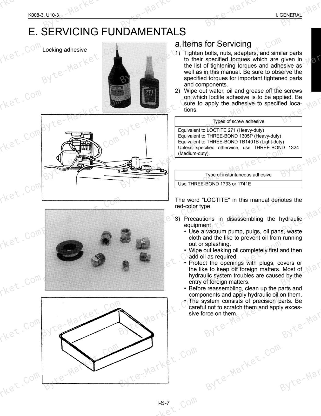
- E. SERVICING FUNDAMENTALS — p. 12
- a. Items for Servicing — p. 12
- b. O-ring, Oil Seal, Circlip and Roll Pin — p. 14
- c. Piping — p. 16
- F. MACHINE QUALITY SPECIFICATIONS — p. 22
- a. K008-3, U10-3 EU-Version — p. 22
- b. K008-3 KTC, KCL, KTA-Version — p. 27
- G. MAINTENANCE INTERVALS — p. 34
- a. K008-3, U10-3 EU-version — p. 34
- b. K008-3, U10-3 KTC, KCL-Version — p. 35
- c. K008-3, U10-3 KTA-Version — p. 36
- d. Periodic Replacement of Important Component Parts — p. 37
- e. Hydraulic Oil Check for Machines with Hydraulic Breakers — p. 38
- H. SUMMARY OF MINOR CHANGE CONTENTS — p. 40
- a. Development Background — p. 40
- b. Meeting the EU Safety Regulation — p. 40
- c. Main Items of Minor Change — p. 41
- d. Main Performance Specifications and Comparison — p. 42
- II.MACHINE BODY (Mechanism Section) — p. 46
- A. SPECIFICATIONS — p. 48
- a. EU-Version — p. 48
- b. KTC, KCL, KTA-Version — p. 49
- c. EU-Version, Minor Change — p. 50
- B. COMPONENT INTERCHANGEABILITY — p. 10
- a. Bucket — p. 10
- C. MACHINE STRUCTURE — p. 54
- a. Control Linkage — p. 54
- b. Engine Mount — p. 59
- c. Undercarriage — p. 60
- A. SPECIFICATIONS — p. 48
- II.MACHINE BODY (Service Section) — p. 64
- A. SPECIFICATIONS — p. 66
- a. Machine Weight — p. 66
- b. Machine Specifications — p. 67
- c. Lever Stroke and Operating Force — p. 69
- d. Dimensions of Parts — p. 71
- B. FRONT ATTACHMENT — p. 80
- a. Front Attachment Assembly Procedure — p. 80
- b. Greasing Points — p. 83
- c. Shim Adjustment — p. 84
- C. UPPER STRUCTURE — p. 86
- a. Operating Unit — p. 86
- b. Dozer Lever — p. 92
- c. Swing Pedal — p. 94
- d. Service Port Pedal — p. 96
- e. TPSS (Two Pattern Selection System) — p. 99
- f. Weight — p. 102
- g. ROPS (Rear Mount Type) — p. 104
- h. Seat Belt Setup Angle (Rear Mount Type) — p. 107
- i. ROPS (Front Mount Type) (EU-Version) — p. 108
- j. Seat Belt (EU-Version) — p. 110
- D. UNDERCARRIAGE — p. 112
- a. Swivel Bearing — p. 112
- b. Traveling Unit — p. 116
- c. Drive Sprocket — p. 120
- d. Track Frame (Retractable - version) — p. 121
- A. SPECIFICATIONS — p. 66
- III.ENGINE (Mechanism Section) — p. 126
- A. SAFETY FIRST — p. 128
- B. ENGINE SPECIFICATIONS FOR CONSTRUCTION MACHINERY — p. 130
- C. ENGINE ELECTRIC COMPONENTS — p. 132
- D. ENGINE CHANGE FOR EPA EMISSION CONTROL — p. 134
- E. PERFORMANCE CURVE — p. 136
- F. DIMENSION — p. 140
- III.ENGINE (Service Section) — p. 166
- A. TANK — p. 168
- B. ENGINE MOUNT ON THE MACHINE — p. 176
- C. GENERAL — p. 178
- IV.HYDRAULIC SYSTEM (Mechanism Section) — p. 246
- A. MAIN PUMP (K008-3, U10-3) — p. 248
- B. PILOT PUMP (U10-3) — p. 250
- C. CONTROL VALVE — p. 252
- a. Specifications — p. 252
- b. General View of Control Valve — p. 254
- c. Sectional View — p. 258
- d. Structure and Function — p. 270
- D. PILOT VALVE — p. 272
- a. Structure — p. 272
- b. Pilot Valve Control Diagram — p. 274
- c. Function — p. 275
- E. HYDRAULIC PILOT CIRCUIT — p. 278
- a. Oil Flow when the Control Lever is Locked (A) — p. 279
- b. Oil Flow when the Control Lever is Locked (B) — p. 281
- c. Oil Flow in Boom Lifting Operation — p. 283
- d. Oil Flow in Bucket Dumping Operation — p. 285
- e. Oil Flow in Arm Crowding Operation — p. 287
- f. Oil Flow in Right Swivel Operation — p. 289
- F. SWIVEL MOTOR (K008-3, U10-3) — p. 292
- a. Structure and Specifications — p. 292
- b. Operating Principle — p. 294
- G. ROTARY JOINT (SWIVEL JOINT) — p. 296
- H. TRAVEL MOTOR — p. 298
- a. Single Speed Motor (K008, EU-Version) — p. 298
- b. Two Speed Motor — p. 301
- I. ORBITROL MOTOR: STRUCTURE & FUNCTION — p. 304
- a. Basic Function — p. 304
- b. Structure & Function: Shaft Output Type — p. 306
- c. Structure & Function: Ring Output Type — p. 315
- J. HYDRAULIC CIRCUIT DIAGRAM — p. 326
- a. K008-3: Travel 1st Speed Type — p. 326
- b. K008-3: Travel 2nd Speed Type — p. 327
- c. U10-3: Travel 1st Speed Type — p. 328
- d. U10-3: Travel 2nd Speed Type — p. 329
- e. Hydraulic Components Layout: K008-3 — p. 330
- IV.HYDRAULIC SYSTEM (Service Section) — p. 332
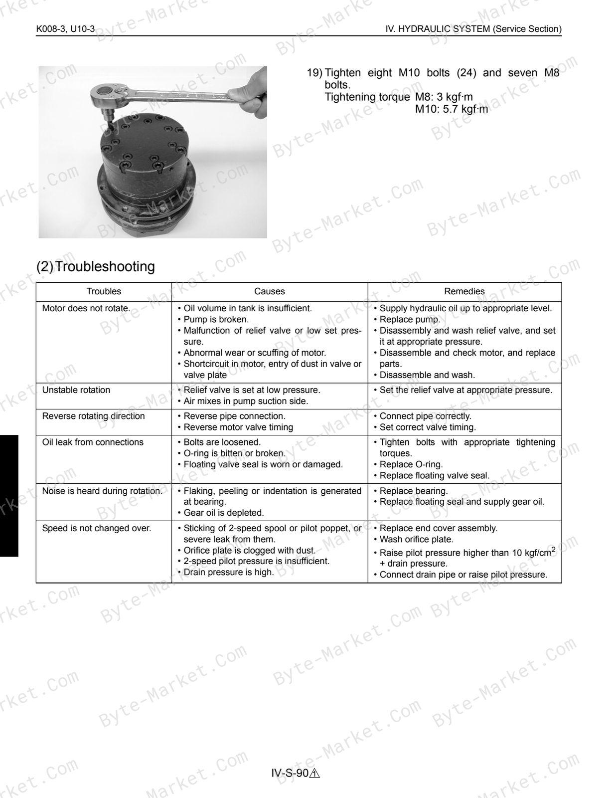
- A. TROUBLESHOOTING — p. 334
- a. Machine General — p. 334
- b. Hydraulic System — p. 337
- B. SPECIFICATIONS — p. 342
- a. Pump System — p. 342
- b. List of Relief Valves — p. 344
- c. Noise — p. 345
- d. Swivel System — p. 346
- e. Traveling System — p. 347
- f. Cylinder System — p. 348
- C. TESTING — p. 352
- a. Pump Flow Test — p. 352
- b. Pilot Pressure (U10-3) — p. 353
- c. Main Relief Valve Pressure — p. 354
- d. Operating Speed — p. 355
- e. Travel Straightness Measurement Test — p. 358
- f. Traveling Motor Block Performance — p. 358
- g. Swivel Motor Block Performance — p. 359
- h. Cylinder Natural Fall Amount — p. 359
- i. Control and Traveling Lever Operating Force — p. 360
- j. Lever Stroke — p. 360
- D. DISASSEMBLING AND ASSEMBLING — p. 362
- a. Pump Coupling — p. 362
- b. Pump — p. 363
- c. Control Valve — p. 368
- d. Pilot Valve — p. 371
- e. U10-3 Component Parts of Hydraulic Operating Unit — p. 372
- f. Pilot Valve — p. 377
- g. Swivel Motor — p. 391
- h. Swivel Joint — p. 403
- i. Wheel Motor — p. 407
- j. Cylinder — p. 424
- k. Route of Hydraulic Hose — p. 430
- l. Accumulator — p. 439
- m. Tank — p. 440
- n. Service Port Operation — p. 441
- A. TROUBLESHOOTING — p. 334
- V.ELECTRICAL SYSTEM (Service Section) — p. 444
- A. WIRING DIAGRAM — p. 446
- a. K008-3, U10-3 — p. 446
- b. Wiring Diagram, K008-3, U10-3 — p. 447
- B. ELECTRIC WIRING — p. 448
- a. Cautions on Electric Wire Clamping Method — p. 448
- b. Harness Route — p. 448
- C. TROUBLESHOOTING OF ELECTRIC SYSTEM — p. 456
- a. Outline of Troubleshooting — p. 456
- b. Cautions in General — p. 457
- c. Troubleshooting — p. 462
- d. Checking Procedure — p. 464
- A. WIRING DIAGRAM — p. 446
- VI. SIDE LEVER MODEL (U10-3SL) — p. 478
- INFORMATION — p. 479
- 1. APPEARANCE — p. 480
- 2. LABELS DISPLAYED TO PROMOTE WORKSAFETY — p. 481
- SERVICING — p. 483
- 1. CANOPY — p. 484
- 2. PILOT VALVE — p. 486
- 3. PILOT VALVE SUPPORT — p. 489
- 4. ROUTING OF HYDRAULIC HOSES — p. 497
- 5. HYDRAULIC HOSE ROUTING — p. 498
- 6. UNLOAD VALVE — p. 500
- 7. MAGNET SWITCH — p. 501
- 8. GAS SPRING — p. 502
- 9. HARNESS ROUTING — p. 503
- 10. HARNESS CLAMP POSITIONS — p. 505
- APPENDICES — p. 506
- INFORMATION — p. 479
- Ⅶ.UNLOAD LEVER SPEC. (U10-3UL) From 50001 — p. 510
- INFORMATION — p. 511
- 1. APPEARANCE — p. 512
- 2. MACHINE DEVICE LAYOUT — p. 513
- 3. IDENTIFICATION OF THE EXCAVATOR — p. 514
- 4. FUSE LAYOUT — p. 515
- 5. UNLOAD VALVE — p. 516
- [1] SPECIFICATIONS — p. 516
- [2] FUNCTION — p. 517
- SERVICING — p. 518
- 1. UNLOAD LEVER ASSEMBLY OVERVIEW — p. 519
- 2. ACCUMULATER ASSEMBLY OVERVIEW — p. 520
- 3. HYDRAULIC HOSE ROUTING — p. 521
- 4. ASSEMBLING UNLOAD VALVE — p. 522
- 5. HARNESS ROUTING — p. 523
- APPENDICES — p. 527
- INFORMATION — p. 511
- Conversion Tables — p. 530
- R REVISED CONTENTS — p. 532
- REVISED CONTENTS — p. 533
- 1. BODY AND ENGINE IDENTIFICATION MARKS — p. 534
- 2. MEASURING THE SWIVEL BEARING VERTICALPLAY — p. 538
- REVISED CONTENTS — p. 533
Capabilities
The source outline indexes servicing instructions, disassembly and assembly, maintenance tasks, checking and adjustment, mechanism explanations, and troubleshooting. Use these source-backed headings to locate the applicable task or system in the source PDF, then confirm model-specific notes, specifications, illustrations, and operating conditions at the relevant page before carrying out service work.
Keep the source's safety sequence, prerequisite steps, labels, units, configuration notes, and footnotes with the selected task; do not apply an isolated value outside the conditions stated in the manual.
Technical reference
Reference tables include torque settings for service checks, adjustment work, and specification lookup. Use the values and conditions in the PDF for the applicable model and procedure.
- Service limits and settings: torque settings.
Delivery
This manual is supplied as a digital PDF file and is available for instant download after purchase. No physical media is shipped.
References
Kubota Workshop Manual for Excavator, document code 97899-60736, PDF edition.


No questions found.