
Kubota Workshop Manual
Kubota SVL75-3 Workshop Manual
Document number RY911-31065 · English PDF edition · 976 pages
About this manual
Kubota published this Workshop Manual for the SVL75-3 compact track loader models. It brings the documented service and technical-reference material for those named compact track loaders into a single publication.
The manual is especially useful for work that crosses electrical and hydraulic systems: it includes electrical troubleshooting with connector views and pinouts, alongside hydraulic diagrams, pressure-test evidence, and valve-adjustment information.
Use the Manual Contents below to check that the exact repair, inspection, or maintenance procedure you need is included in this publication.
Manual details
- Manufacturer
- Kubota
- Manual type
- Workshop Manual
- Models
- SVL75-3
- Document number
- RY911-31065
- Publication year
- 2024
- Language
- English
- Page count
- 976
Product highlights
Electrical systems
The manual includes wiring diagrams, electrical troubleshooting, connector views, and pinouts.
Hydraulic systems
The manual includes hydraulic circuit diagrams, hydraulic pressure-test material, and hydraulic valve-adjustment material.
Diagnostics
The manual includes diagnostic trouble-code reference information.
Specifications and settings
The manual includes reference information for torque specifications, wear limits, clearances, capacities, and speed ratings.
Special tools
A special-tools section is included.
Maintenance
The manual includes a maintenance schedule.
Manual contents
Use these source headings to locate the task or system you need in the PDF.
- CONTENTS — p. 11
- 1. SAFETY — p. 27
- SAFETY FIRST — p. 29
- 1. Preparing for emergencies — p. 29
- 2. Working cautions — p. 29
- 3. Starting machine safely — p. 30
- 4. Preventing fires — p. 30
- 5. Preventing acid burns — p. 31
- 6. Avoiding high pressure fluid — p. 31
- 7. Avoiding hot exhaust — p. 31
- 8. Cleaning exhaust filter — p. 32
- SAFE OPERATION — p. 33
- 1. Precautions before operation of the machine — p. 33
- 1.1 General precautions — p. 33
- 1.2 Precautions of ROPS and FOPS — p. 34
- 2. Precautions for operating the machine — p. 34
- 2.1 Safety for children — p. 36
- 2.2 Avoiding crystalline silica (quartz) dust — p. 36
- 3. Parking the machine — p. 37
- 4. Precautions for safely loading and transporting the machine — p. 37
- 5. Precautions for maintenance — p. 37
- 5.1 Preparing maintenance — p. 37
- 5.2 Checking items for maintenance — p. 37
- 6. Safety labels for English label — p. 42
- 7. Safety labels for French (Canadian) label — p. 49
- 7.1 Care for safety labels — p. 56
- 1. Precautions before operation of the machine — p. 33
- SAFETY FIRST — p. 29
- 2. GENERAL — p. 57
- GENERAL WORKING INSTRUCTIONS — p. 59
- 1. General working precautions — p. 59
- 2. Tightening bolts and nuts — p. 59
- 3. Applying thread-locking fluid — p. 59
- 4. Installing circlips — p. 60
- 5. Installing spring pins — p. 60
- 6. Handling split pin — p. 60
- 7. Handling chain joint and split pin — p. 60
- 8. Handling liquid gasket — p. 61
- 9. Replacing O-rings — p. 61
- 10. Replacing oil seals — p. 61
- 11. Replacing floating seals — p. 62
- 12. Connecting hydraulic hoses — p. 62
- 13. Wrapping thread seal tape — p. 62
- 14. Installing elbows with male seat — p. 62
- 15. Connecting and disconnecting quick hose couplings — p. 63
- 16. Handling the battery — p. 63
- 17. Handling wire harness — p. 63
- 18. Handling fuses — p. 65
- 19. Handling connectors — p. 65
- 20. Wiring color — p. 66
- 21. Washing the machine with a high pressure washer — p. 66
- 22. Dispose fluids correctly — p. 67
- 23. Checking hoses — p. 67
- PRELIMINARY WORKING INSTRUCTIONS — p. 69
- 1. Removing and installing the battery — p. 69
- 2. Jacking up the machine — p. 69
- 3. Vacuuming the hydraulic oil tank — p. 72
- 4. Vacuuming the refrigerant — p. 72
- 5. Connecting the diagnosis tool — p. 73
- 6. How to use the lift arm stopper — p. 73
- 7. Opening and closing the rear door — p. 74
- 8. Opening the rear upper cover — p. 75
- 9. Opening the air-conditioner condenser — p. 76
- 10. Opening the fan motor cover — p. 77
- 11. Discharging mud from the main frame — p. 77
- 12. Tilting up the cab — p. 77
- 13. Adjusting the tracks — p. 79
- CONCLUDING WORKING INSTRUCTIONS — p. 83
- 1. Bleeding the air from the hydraulic cylinder — p. 83
- 2. Charging the refrigerant — p. 83
- 3. Setting the new main ECU — p. 84
- TIGHTENING TORQUES — p. 87
- 1. Bolts and nuts tightening torque — p. 87
- 2. Stud bolts tightening torque — p. 87
- 3. Hydraulic hose fitting tightening torque — p. 88
- 4. Hydraulic hoses tightening torque (taper thread) — p. 88
- 5. Locknuts of adapters with O-ring tightening torque (straight thread) — p. 88
- 6. Adapters tightening torque (taper thread) — p. 89
- 7. Hose clamps tightening torque — p. 89
- 8. Hydraulic pipe tightening torque — p. 90
- GENERAL MACHINE INFORMATION — p. 91
- 1. Machine identification — p. 91
- 2. Engine model identification — p. 91
- 3. E5AB engine — p. 93
- 4. DPF muffler model identification — p. 93
- 5. Injector code identification — p. 94
- 6. Specification table — p. 95
- 7. Main dimensions of the machine — p. 97
- 8. Machine mass table — p. 99
- GENERAL ELECTRICAL INFORMATION — p. 101
- 1. Electrical circuit general description — p. 101
- 1.1 Electrical circuit diagram description — p. 101
- 1.2 Electrical circuit diagram unit symbol — p. 101
- 1.3 Electrical wiring color coding — p. 102
- 1.4 Electrical wiring clamp — p. 102
- 1.5 Bus description — p. 103
- 1.6 Composite terminal description — p. 103
- 2. Connector — p. 103
- 2.1 Connector handling precaution — p. 103
- 2.2 Connector diagram description — p. 103
- 1. Electrical circuit general description — p. 101
- TRANSPORTING THE MACHINE — p. 105
- 1. Loading and unloading the machine on a truck — p. 105
- 2. Towing the inoperable machine — p. 106
- SPECIAL TOOLS — p. 109
- 1. Special tools for the engine section — p. 109
- 1.1 Compression tester adapter — p. 109
- 2. Special tools for the hydraulic system section — p. 111
- 2.1 U-joint tightening jig — p. 111
- 2.2 Hydraulic cylinder special jigs — p. 112
- 3. Special tools for the air conditioning section — p. 114
- 3.1 Manifold gauge — p. 114
- 3.2 Charging hoses — p. 114
- 3.3 Refrigerant gas vacuum machine — p. 115
- 3.4 Refrigerant gas leak tester — p. 115
- 3.5 Refrigerant gas canister — p. 115
- 1. Special tools for the engine section — p. 109
- GENERAL WORKING INSTRUCTIONS — p. 59
- 3. MAINTENANCE — p. 117
- MAINTENANCE INTERVALS TABLE (SERIAL NUMBER: TO 30321) — p. 119
- MAINTENANCE INTERVALS TABLE (SERIAL NUMBER: FROM 30322) — p. 123
- LUBRICANT QUANTITY — p. 127
- RECOMMENDED OILS — p. 129
- 1. Recommended oils, greases, and fuels — p. 129
- 2. Biodiesel fuel (BDF) — p. 131
- DAILY CHECK — p. 133
- 1. Daily check items before starting the machine — p. 133
- 2. Checking the coolant level — p. 133
- 3. Checking the fuel level — p. 133
- 4. Checking the engine oil level — p. 134
- 5. Checking the hydraulic oil level — p. 134
- 6. Lubrication points of the machine — p. 135
- 7. Checking the radiator and the oil cooler — p. 135
- 8. Checking and cleaning the engine and the electrical wiring — p. 136
- 9. Precautions for checking the fan belt — p. 136
- 10. Precautions for washing whole machine — p. 136
- 11. Draining the water separator — p. 136
- 12. Checking the evacuator valve — p. 137
- 13. Checking the pre-cleaner — p. 137
- 14. Checking the DPF (diesel-particulate-filter) muffler — p. 137
- 15. Checking the washer liquid [Closed cab model] — p. 138
- 16. Checking the battery condition — p. 138
- 17. Checking the air-conditioner condenser and the reverse fan — p. 139
- 18. Cleaning the fuel tank cap — p. 140
- 19. Cleaning the fuel breather cap — p. 140
- 20. Precautions for checking the air-conditioner belt — p. 141
- 21. Checking the fresh air filter — p. 141
- 21.1 Cleaning the fresh air filter — p. 141
- 22. Checking the recirculation air filter — p. 142
- 22.1 Cleaning the recirculation air filter — p. 142
- EVERY 50 SERVICE HOURS — p. 145
- 1. Draining the water from the fuel tank — p. 145
- 2. Checking the track tension — p. 145
- 3. Checking the air cleaner element — p. 146
- 4. Cleaning the air cleaner element — p. 146
- 5. Cleaning the evacuator valve — p. 147
- EVERY 250 SERVICE HOURS — p. 149
- 1. Checking the radiator hoses and the clamps — p. 149
- 2. Checking the fuel line and the intake air line — p. 149
- 3. Checking and adjusting the fan belt tension — p. 149
- 3.1 Checking and adjusting the air-conditioner belt tension — p. 150
- 4. Cleaning inside of the main frame — p. 151
- 5. Replacing the air cleaner element — p. 151
- 6. Cleaning under the rear upper cover 5 — p. 152
- EVERY 500 SERVICE HOURS — p. 153
- 1. Changing the engine oil — p. 153
- 2. Replacing the engine oil filter cartridge — p. 153
- 3. Replacing the water separator filter element — p. 154
- 4. Replacing the fuel filter cartridge — p. 154
- 5. Changing the travel motor gear oil — p. 154
- 6. Changing the return filter — p. 155
- 7. Replacing the hydraulic breather filter — p. 155
- 8. Replacing the hydraulic oil filter — p. 155
- 9. Cleaning the front window roller — p. 156
- 10. Checking the air-conditioner drain — p. 157
- 11. Replacing the air filter — p. 157
- EVERY 1000 SERVICE HOURS — p. 159
- 1. Changing the hydraulic oil including the suction filter in the hydraulic tank and the return filter — p. 159
- 2. Hydraulic oil check with the hydraulic hammers — p. 160
- 3. Adjusting the engine valve clearance — p. 160
- 4. Replacing the front window roller — p. 165
- EVERY 1500 SERVICE HOURS — p. 167
- 1. Checking the injector — p. 167
- 2. Checking the EGR cooler — p. 167
- EVERY 2000 SERVICE HOURS — p. 169
- 1. Checking the starter motor and alternator — p. 169
- EVERY 3000 SERVICE HOURS — p. 171
- 1. Checking the EGR valve — p. 171
- 2. Checking the turbocharger — p. 171
- 3. Replacing the fuel tank breather — p. 172
- EVERY 3000 TO 8000 SERVICE HOURS — p. 173
- 1. Cleaning the DPF muffler — p. 173
- ANNUAL SERVICING — p. 175
- 1. Checking the air conditioning and heater hoses — p. 175
- 2. Checking the exhaust gas line — p. 175
- 3. Checking the intake air line — p. 176
- 4. Checking the boost pressure sensor — p. 176
- 5. Checking the DPF muffler — p. 177
- 6. Checking the DPF differential pressure sensor and DPF differential pressure sensor rubber piping — p. 177
- 7. Checking the DPF exhaust gas temperature sensor — p. 178
- 8. Checking the EGR and EGR piping — p. 178
- 9. Checking the CCV heater — p. 179
- 10. Checking the CCV pressure switch (Closed cab model only) — p. 180
- 11. Checking the CCV relief valve (Closed cab model only) — p. 180
- BIENNIAL SERVICING — p. 183
- 1. Replacing the hydraulic hoses — p. 183
- 2. Changing the radiator coolant — p. 183
- 3. Replacing the fuel hoses — p. 185
- 4. Replacing the intake air line — p. 185
- 5. Replacing the radiator hoses — p. 185
- 6. Replacing the coolant rubber piping — p. 185
- 7. Replacing the air conditioning and heater hoses — p. 186
- 8. Replacing the CCV rubber piping — p. 186
- 9. Replacing the DPF differential pressure sensor rubber piping — p. 187
- 10. Replacing the suction hoses upstream and downstream the turbocharger — p. 187
- 11. Replacing the boost pressure sensor rubber piping — p. 187
- 12. Replacing the EGR differential pressure sensor rubber piping — p. 188
- 13. Replacing the EGR cooler hose — p. 188
- SERVICING AS REQUIRED — p. 191
- 1. Checking the refrigerant — p. 191
- 2. Draining the water separator in case warning against water of the fuel filter — p. 191
- 3. Purging of the fuel system — p. 191
- 4. Cleaning the plastic parts and synthetic leather — p. 192
- 4. MACHINE BODY — p. 193
- MECHANISM — p. 195
- 1. Machine device layout — p. 195
- 2. Bucket — p. 196
- 2.1 Bucket dimensions — p. 196
- 3. Rubber track — p. 197
- 3.1 Rubber track dimensions — p. 197
- 4. Front idler — p. 197
- 4.1 Front idler dimensions — p. 197
- 5. Rear idler — p. 197
- 5.1 Rear idler dimensions — p. 197
- 6. Track roller — p. 198
- 6.1 Track roller dimensions — p. 198
- 7. Sprocket — p. 198
- 7.1 Sprocket dimensions — p. 198
- 8. Pins, bushings, and shims — p. 199
- 8.1 Pin, bushing, and shim dimensions — p. 199
- SERVICING — p. 203
- 1. Service specifications — p. 203
- 1.1 Service specifications for machine body — p. 203
- 2. Testing — p. 205
- 2.1 Measuring the operating force for levers and pedal — p. 205
- 3. Repairing — p. 205
- 3.1 Lift arm — p. 205
- 3.1.1 Removing and installing the lift arm — p. 205
- 3.2 Cab — p. 211
- 3.2.1 Removing and installing the cab — p. 211
- 3.3 Seat — p. 217
- 3.3.1 Removing and installing the seat — p. 217
- 3.4 Armrest — p. 218
- 3.4.1 Removing and installing the armrests — p. 218
- 3.5 Accelerator pedal — p. 220
- 3.5.1 Removing the accelerator pedal — p. 220
- 3.6 Rubber track — p. 221
- 3.6.1 Removing and installing the rubber track — p. 221
- 3.7 Front idler — p. 223
- 3.7.1 Removing and installing the front idler — p. 223
- 3.8 Rear idler — p. 224
- 3.8.1 Removing and installing the rear idler — p. 224
- 3.9 Track roller — p. 226
- 3.9.1 Removing and installing the track roller — p. 226
- 3.10 Tension spring — p. 227
- 3.10.1 Removing and installing the tension spring — p. 227
- 3.11 Grease cylinder — p. 228
- 3.11.1 Removing the grease cylinder — p. 228
- 3.12 Quick hitch — p. 229
- 3.12.1 Removing and installing the quick hitch — p. 229
- 3.13 Front window — p. 230
- 3.13.1 Removing and installing the front window — p. 230
- 3.1 Lift arm — p. 205
- 1. Service specifications — p. 203
- MECHANISM — p. 195
- 5. ENGINE — p. 237
- MECHANISM — p. 239
- 1. Engine device layout — p. 239
- 2. Engine specifications — p. 243
- 3. Engine dimensions — p. 245
- 4. Engine performance curves — p. 246
- 5. Lubricating system — p. 247
- 5.1 Lubricating system general description — p. 247
- 6. Cooling system — p. 247
- 6.1 Cooling system general description — p. 247
- 7. Turbocharger system — p. 248
- 7.1 Turbocharger system general description — p. 248
- 8. Intake air system — p. 248
- 8.1 Intake air system general description — p. 248
- 9. EGR system — p. 249
- 9.1 EGR system general description — p. 249
- 10. Common rail system — p. 250
- 10.1 Common rail system general description — p. 250
- 11. Aftertreatment system — p. 251
- 11.1 Aftertreatment system general description — p. 251
- 11.2 DPF regeneration control — p. 252
- SERVICING — p. 255
- 1. Service specifications — p. 255
- 1.1 Service specifications for engine — p. 255
- 2. Testing — p. 255
- 2.1 Measuring engine compression pressure — p. 255
- 2.2 Measuring engine oil pressure — p. 258
- 2.3 Measuring crankcase pressure — p. 259
- 3. Repairing — p. 260
- 3.1 Fuel hose and tank — p. 260
- 3.1.1 Removing and installing the fuel tank — p. 260
- 3.1.2 Fuel hose routing — p. 263
- 3.2 Engine — p. 266
- 3.2.1 Removing and installing the engine — p. 266
- 3.2.2 Removing and installing the alternator — p. 274
- 3.2.3 Removing and installing the starter motor — p. 275
- 3.2.4 Removing and installing the rail — p. 276
- 3.2.5 Removing and installing the injector — p. 278
- 3.2.6 Removing and installing the turbocharger — p. 284
- 3.2.7 Removing and installing the EGR valve — p. 287
- 3.2.8 Removing and installing the EGR cooler — p. 290
- 3.2.9 Removing the throttle valve — p. 292
- 3.3 Radiator — p. 293
- 3.3.1 Removing and installing radiator and oil cooler — p. 293
- 3.4 DPF muffler — p. 298
- 3.4.1 Removing and installing the DPF muffler — p. 298
- 3.1 Fuel hose and tank — p. 260
- 1. Service specifications — p. 255
- MECHANISM — p. 239
- 6. HYDRAULIC SYSTEM — p. 301
- MECHANISM — p. 303
- 1. Hydraulic device layout — p. 303
- 2. Hydraulic system general description — p. 307
- 2.1 HST system general description — p. 307
- 2.2 Front attachment system general description — p. 308
- 2.3 Pilot system general description — p. 309
- 3. HST pump — p. 310
- 3.1 HST pump specifications — p. 310
- 3.2 HST pump hydraulic circuit — p. 311
- 3.3 HST pump function and structure — p. 312
- 3.3.1 HST pump working principles — p. 312
- 3.3.2 Charging — p. 314
- 3.3.3 High pressure relief valve — p. 314
- 3.3.4 Charge relief valve — p. 314
- 3.3.5 Forward traveling circuit — p. 316
- 3.3.6 Backward traveling circuit — p. 317
- 4. Gear pump — p. 318
- 4.1 Gear pump specifications — p. 318
- 4.2 Gear pump working principles — p. 320
- 5. HST motor — p. 321
- 5.1 HST motor specifications — p. 321
- 5.2 HST motor hydraulic circuit — p. 323
- 5.3 HST motor function and structure — p. 324
- 5.3.1 HST motor working principles — p. 324
- 5.3.2 Parking brake — p. 325
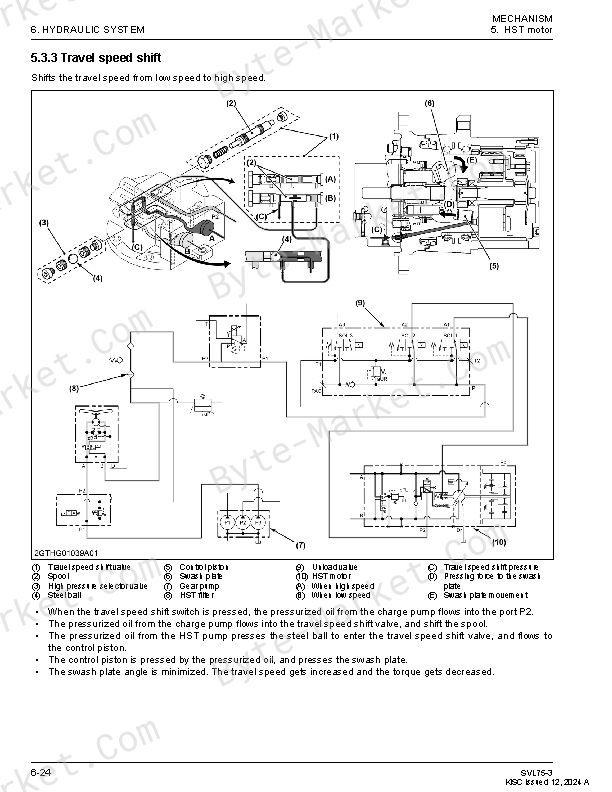
- 5.3.3 Travel speed shift — p. 326
- 5.3.4 Backward traveling circuit — p. 327
- 5.3.5 Flushing — p. 328
- 6. Fan motor — p. 329
- 6.1 Fan motor specifications — p. 329
- 6.2 Fan motor hydraulic circuit — p. 331
- 6.3 Fan motor function and structure — p. 331
- 6.3.1 Fan motor working principles — p. 331
- 7. Control valve — p. 333
- 7.1 Control valve specifications — p. 333
- 7.2 Control valve hydraulic circuit — p. 337
- 7.3 Control valve spool shift performance — p. 339
- 7.4 Control valve function and structure — p. 339
- 7.4.1 Main relief valve — p. 339
- 7.4.2 Overload relief valve — p. 340
- 7.4.3 Lift arm operation circuit — p. 341
- 7.4.4 Bucket operation circuit — p. 343
- 7.4.5 AUX operation circuit — p. 345
- 7.4.6 High-flow circuit — p. 346
- 7.4.7 Self leveling circuit — p. 347
- 7.4.8 Float operation circuit — p. 349
- 8. Hydraulic cylinder — p. 351
- 8.1 Hydraulic cylinder specifications — p. 351
- 9. Pilot control valve — p. 352
- 9.1 Pilot control valve specifications — p. 352
- 9.2 Pilot control valve performance diagram — p. 353
- 9.3 Pilot control valve function and structure — p. 355
- 10. Unload valve — p. 357
- 10.1 Unload valve (travel speed shift, parking brake, work equipment) specifications — p. 357
- 10.2 Unload valve function and structure — p. 359
- 10.2.1 Unload valve (Travel speed shift, parking brake, work equipment) working principles — p. 359
- 10.2.2 Warmup function — p. 359
- 11. Anti-stall solenoid valve — p. 360
- 11.1 Anti-stall solenoid valve specifications — p. 360
- 12. Hydraulic quick hitch solenoid valve — p. 361
- 12.1 Hydraulic quick hitch solenoid valve specifications — p. 361
- 12.2 Hydraulic quick hitch solenoid valve function and structure — p. 362
- 12.2.1 Hydraulic quick hitch solenoid valve working principles — p. 362
- 13. Fan control valve — p. 363
- 13.1 Fan control valve specifications — p. 363
- 13.2 Fan control valve performance diagram — p. 364
- SERVICING — p. 365
- 1. Service specifications — p. 365
- 1.1 Service specifications for hydraulic system — p. 365
- 2. Testing — p. 367
- 2.1 Measuring the hydraulic devices — p. 367
- 2.1.1 Measuring the lift arm cylinder speed — p. 367
- 2.1.2 Measuring the bucket cylinder speed — p. 368
- 2.1.3 Measuring the travel speed — p. 368
- 2.1.4 Measuring the cylinder internal leakage — p. 368
- 2.1.5 Measuring the HST motor internal leakage — p. 369
- 2.1.6 Testing the travel straightness — p. 370
- 2.1.7 Measuring the self-leveling — p. 371
- 2.2 Measuring the HST pump — p. 372
- 2.2.1 Measuring the HST pump flow rate — p. 372
- 2.2.2 Measuring the high pressure relief valve pressure — p. 373
- 2.2.3 Measuring the charge relief valve pressure — p. 374
- 2.3 Measuring the main pump — p. 375
- 2.3.1 Measuring the main pump flow rate — p. 375
- 2.3.2 Measuring the AUX flow rate — p. 376
- 2.4 Measuring the high-flow pump — p. 377
- 2.4.1 Measuring the high-flow pump flow rate — p. 377
- 2.4.2 Measuring the high-flow relief pressure — p. 377
- 2.5 Measuring the charge pump — p. 378
- 2.5.1 Measuring the charge pump flow rate — p. 378
- 2.5.2 Measuring the charge pump relief pressure — p. 379
- 2.6 Measuring the control valve — p. 380
- 2.6.1 Measuring the main relief valve pressure — p. 380
- 2.6.2 Measuring the overload relief valve pressure — p. 381
- 2.7 Measuring the unload valve — p. 382
- 2.7.1 Measuring the unload valve relief pressure — p. 382
- 2.8 Measuring the pilot control valve — p. 383
- 2.8.1 Measuring the pilot primary pressure — p. 383
- 2.8.2 Measuring the pilot secondary pressure — p. 384
- 2.1 Measuring the hydraulic devices — p. 367
- 3. Repairing — p. 385
- 3.1 HST pump — p. 385
- 3.1.1 Removing and installing the HST pump — p. 385
- 3.1.2 HST pump components — p. 389
- 3.1.3 Disassembling the HST pump — p. 393
- 3.1.4 Assembling the HST pump — p. 400
- 3.1.5 Installing adapters for the HST pump — p. 410
- 3.1.6 Removing and installing the pump coupling — p. 411
- 3.2 Gear pump — p. 412
- 3.2.1 Removing and installing the gear pump — p. 412
- 3.2.2 Disassembling the gear pump (standard flow specification) — p. 413
- 3.2.3 Assembling the gear pump (standard flow specification) — p. 416
- 3.2.4 Disassembling the gear pump (high-flow specification) — p. 420
- 3.2.5 Assembling the gear pump (high-flow specification) — p. 425
- 3.2.6 Installing adapters for the gear pump — p. 432
- 3.3 Control valve — p. 434
- 3.3.1 Removing and installing the control valve — p. 434
- 3.3.2 Control valve components — p. 435
- 3.3.3 Disassembling and assembling the control valve — p. 438
- 3.3.4 Installing adapters for the control valve — p. 444
- 3.4 HST motor — p. 446
- 3.4.1 Removing and installing the HST motor — p. 446
- 3.4.2 HST motor components — p. 450
- 3.4.3 Disassembling the HST motor — p. 452
- 3.4.4 Assembling the HST motor — p. 463
- 3.4.5 Installing adapters for the HST motor — p. 478
- 3.5 Fan motor — p. 479
- 3.5.1 Removing and installing the fan motor — p. 479
- 3.5.2 Fan motor components — p. 481
- 3.5.3 Disassembling the fan motor — p. 482
- 3.5.4 Assembling the fan motor — p. 488
- 3.5.5 Installing adapters for the fan motor — p. 495
- 3.6 Hydraulic cylinder — p. 497
- 3.6.1 Lift arm cylinder — p. 497
- 3.6.2 Bucket cylinder — p. 507
- 3.6.3 Hydraulic quick hitch cylinder — p. 516
- 3.6.4 Measuring the hydraulic cylinder — p. 521
- 3.7 Pilot control valve — p. 522
- 3.7.1 Removing and installing the pilot control valve — p. 522
- 3.7.2 Pilot control valve components — p. 525
- 3.7.3 Disassembling the pilot control valve — p. 525
- 3.7.4 Assembling the pilot control valve — p. 529
- 3.7.5 Installing adapters for the pilot control valve — p. 533
- 3.8 Unload valve — p. 533
- 3.8.1 Removing and installing the unload valve — p. 533
- 3.8.2 Unload valve components — p. 535
- 3.8.3 Disassembling and assembling the unload valve — p. 536
- 3.8.4 Installing adapters for the unload valve — p. 538
- 3.9 Anti-stall solenoid valve — p. 538
- 3.9.1 Removing and installing the anti-stall solenoid valve — p. 538
- 3.9.2 Anti-stall solenoid valve components — p. 539
- 3.9.3 Disassembling and assembling the anti-stall solenoid valve — p. 539
- 3.9.4 Installing adapters for the anti-stall solenoid valve — p. 540
- 3.10 Hydraulic quick hitch solenoid valve — p. 540
- 3.10.1 Removing and installing the hydraulic quick hitch solenoid valve — p. 540
- 3.10.2 Hydraulic quick hitch solenoid valve components — p. 544
- 3.10.3 Disassembling and assembling the hydraulic quick hitch solenoid valve — p. 545
- 3.10.4 Installing adapters for the hydraulic quick hitch solenoid valve — p. 546
- 3.11 Fan control valve — p. 546
- 3.11.1 Removing and installing the fan control valve — p. 546
- 3.11.2 Fan control valve components — p. 548
- 3.11.3 Disassembling and assembling the fan control valve — p. 549
- 3.11.4 Installing adapters for the fan control valve — p. 551
- 3.12 Hydraulic oil tank — p. 551
- 3.12.1 Removing and installing the hydraulic oil tank — p. 551
- 3.12.2 Hydraulic oil tank components — p. 559
- 3.12.3 Installing adapters for the hydraulic oil tank — p. 560
- 3.13 Hydraulic hose — p. 561
- 3.13.1 Metal fittings of hydraulic hoses — p. 561
- 3.13.2 Drain hose routing — p. 562
- 3.13.3 Front hose routing — p. 565
- 3.13.4 Pilot hose routing — p. 568
- 3.13.5 Suction hose routing — p. 570
- 3.1 HST pump — p. 385
- 1. Service specifications — p. 365
- MECHANISM — p. 303
- 7. ELECTRICAL SYSTEM — p. 577
- MECHANISM — p. 579
- 1. Electrical device — p. 579
- 1.1 Electrical device layout — p. 579
- 1.2 Switch layout — p. 585
- 1.3 Fuse and relay layout — p. 586
- 1.4 Slow blow fuse layout — p. 589
- 1.5 Communication port layout — p. 589
- 1.6 Ground wiring layout — p. 589
- 2. Functional electrical circuit — p. 590
- 2.1 Power supply electrical circuit diagram — p. 590
- 2.2 Accessory electrical circuit diagram — p. 601
- 2.3 Battery charge electrical circuit diagram — p. 610
- 2.4 Engine start electrical circuit diagram — p. 614
- 2.5 CAN (main bus) circuit diagram — p. 618
- 2.6 CAN (service bus) circuit diagram — p. 622
- 2.7 CAN (INT-I/F bus) circuit diagram — p. 626
- 2.8 AUX operation electrical circuit diagram — p. 627
- 2.9 High-flow electrical circuit diagram — p. 631
- 2.10 Hydraulic unlock electrical circuit diagram — p. 636
- 2.11 Hydraulic quick hitch electrical circuit diagram — p. 641
- 2.12 Float electrical circuit diagram — p. 643
- 2.13 Self-leveling electrical circuit diagram — p. 648
- 2.14 Traveling electrical circuit diagram — p. 652
- 2.15 Travel speed shift electrical circuit diagram — p. 661
- 2.16 Fan motor electrical circuit diagram — p. 671
- 2.17 Sensors electrical circuit diagram — p. 682
- 2.18 Accelerator dial electrical circuit diagram — p. 688
- 2.19 Air conditioning electrical circuit diagram — p. 692
- 2.20 Work light electrical circuit diagram — p. 696
- 2.21 Wiper and washer motor electrical circuit diagram — p. 700
- 2.22 USB electrical circuit diagram — p. 705
- 2.23 Radio electrical circuit diagram — p. 707
- 2.24 Electrical outlet electrical circuit diagram — p. 711
- 2.25 Horn circuit electrical diagram — p. 713
- 3. Meter panel — p. 716
- 3.1 Home screen — p. 716
- 3.2 Meter panel functions — p. 717
- 3.3 Dealer Mode — p. 718
- 3.3.1 Entering the dealer mode — p. 718
- 3.3.2 Dealer mode list — p. 720
- 3.3.3 Diagnostic — p. 722
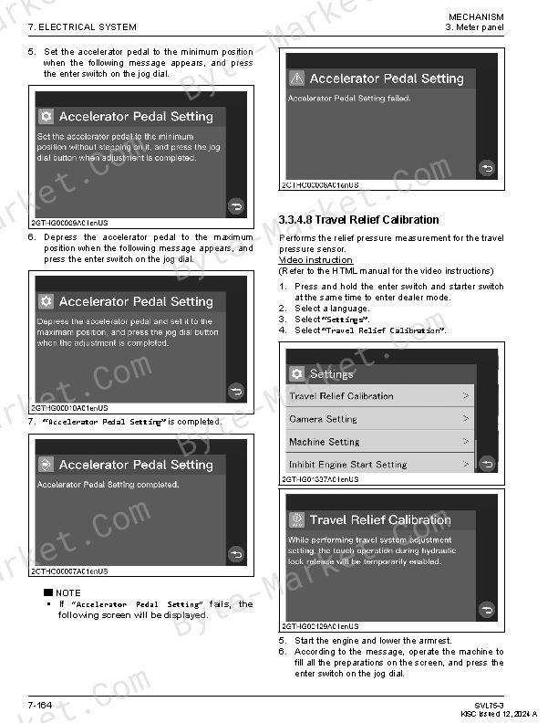
- 3.3.4 Settings — p. 731
- 3.4 Change owner password mode — p. 760
- 3.4.1 Changing owner password — p. 760
- 1. Electrical device — p. 579
- SERVICING — p. 763
- 1. Service specifications for electrical system — p. 763
- MECHANISM — p. 579
- 8. DIAGNOSIS — p. 765
- DIAGNOSIS GENERAL — p. 767
- 1. Diagnostic process — p. 767
- 2. Preliminary diagnosis inspection — p. 767
- 3. Basics of checking electrical/electronic circuit systems — p. 768
- 3.1 Disconnection check — p. 768
- 3.2 Disconnection check — p. 768
- 3.3 Checking voltage — p. 768
- 3.4 Checking for short circuit — p. 769
- 3.5 Checking ground continuity — p. 769
- ERROR WARNING LIST (RED LAMP) — p. 771
- ERROR WARNING LIST (NOT SHOWN ON THE DISPLAY) — p. 781
- ALERT LIST (YELLOW LAMP) — p. 783
- MESSAGE LIST — p. 787
- ENGINE SYSTEM ERROR (RED LAMP) — p. 789
- RECOMMENDED TROUBLESHOOTING AND INSPECTION ITEMS FOR ERRORS — p. 793
- 1. CAN system error (521802-19) — p. 793
- 2. CAN system error (521826-19) — p. 793
- 3. CAN system error (521821-19) — p. 794
- 4. CAN system error (521827-19) — p. 794
- 5. Hyd oil overheat Forced idle (1638-16) — p. 795
- 6. Hyd. temp. sensor err. (1638-3) — p. 796
- 7. Hyd. temp. sensor err. (1638-4) — p. 796
- 8. Fuel Lvl. Sensor Err. (96-3) — p. 797
- 9. Accelerator dial err. (29-2) — p. 797
- 10. Accelerator pedal err. (91-2) — p. 797
- 11. 2-Speed Sys. Error (521652-5) — p. 798
- 12. 2-Speed Sys. Error (521652-4) — p. 798
- 13. Parking Brake Sys. Error (619-5) — p. 799
- 14. Parking Brake Sys. Error (619-4) — p. 799
- 15. Float Sys. Error (521659-5) — p. 800
- 16. Float Sys. Error (521659-4) — p. 800
- 17. Hydraulic Lock Sys. Error (521669-5) — p. 801
- 18. Hydraulic Lock Sys. Error (521669-4) — p. 801
- 19. High-Flow Sys. Error (521662-5) — p. 802
- 20. High-Flow Sys. Error (521662-4) — p. 802
- 21. Hydraulic Hitch Sys. Error (521675-4) — p. 803
- 22. AUX Knob error (521601-2) — p. 804
- 23. Right AUX Solenoid Error (521701-5) — p. 805
- 24. Left AUX Solenoid Error (521702-5) — p. 806
- 25. Anti-stall sys. Error (521706-5) — p. 806
- 26. Overvoltage (168-3) — p. 807
- 27. External 5V sys. err.(short) (3509-1) — p. 807
- 28. Self Leveling Sys. Error (521676-5) — p. 808
- 29. Self Leveling Sys. Error (521676-4) — p. 808
- 30. Meter panel communication error (843-19) — p. 809
- 31. Fan Solenoid Error (521707-5) — p. 809
- 32. Fan Direct. System Error (521671-5) — p. 810
- 33. Fan Direct. System Error (521671-4) — p. 810
- 34. Travel pressure error (521625-3) — p. 811
- 35. Travel pressure error (521625-4) — p. 811
- 36. Travel pressure error (521626-3) — p. 812
- 37. Travel pressure error (521626-4) — p. 812
- 38. Travel pressure error (521627-3) — p. 813
- 39. Travel pressure error (521627-4) — p. 813
- 40. Travel pressure error (521628-3) — p. 813
- 41. Travel pressure error (521628-4) — p. 814
- 42. Travel pilot pressure err. (521629-3) — p. 814
- 43. Travel pilot pressure err. (521629-4) — p. 815
- 44. Travel pilot pressure err. (521630-3) — p. 815
- 45. Travel pilot pressure err. (521630-4) — p. 816
- 46. Travel pilot pressure err. (521631-3) — p. 816
- 47. Travel pilot pressure err. (521631-4) — p. 817
- 48. Travel pilot pressure err. (521632-3) — p. 817
- 49. Travel pilot pressure err. (521632-4) — p. 818
- 50. Engine output is limited (521808-11) — p. 818
- 51. Turn off regen. Inhibit SW (521813-11) — p. 818
- 52. Forced Shutdown to protect DPF (521814-11) — p. 819
- 53. Coolant temp high (521829-1) — p. 819
- 54. Coolant overheat forced idle (110-16) — p. 820
- 55. Engine Oil Pressure Low (100-3) — p. 820
- 56. Charging sys. err. (167-3) — p. 821
- 57. DPF Repair Required (521810-14) — p. 822
- 58. DPF Repair Required (521810-14) — p. 822
- 59. DPF needs replacing (521811-11) — p. 822
- 60. Fan rotation sys. err. (521678-5) — p. 822
- 61. Fan rotation sys. err. (521678-4) — p. 823
- 62. Engine output is limited (521808-11) — p. 823
- 63. Turn off regen. Inhibit SW (521813-11) — p. 824
- 64. Forced Shutdown to protect DPF (521814-11) — p. 824
- 65. Forced Shutdown to protect DPF (521814-11) — p. 824
- 66. CCV system freezing (521829-42) — p. 824
- 67. Accessory power Relay error (3997-5) — p. 825
- 68. Travel pressure error (521625-2) — p. 825
- 69. Travel pressure error (521626-2) — p. 826
- 70. Travel pressure error (521627-2) — p. 826
- 71. Travel pressure error (521628-2) — p. 826
- SYMPTOM LIST — p. 827
- RECOMMENDED TROUBLESHOOTING AND INSPECTION ITEMS BASED ON SYMPTOMS — p. 833
- 1. The travel system and all front attachment operations are slow, weak or do not operate — p. 833
- 2. The lift arm and bucket operations are slow, weak or do not operate when operated independently — p. 834
- 3. The lift arm, bucket, and AUX operation are slow, weak or do not operate, when operated independently — p. 834
- 4. Lift arm up and lift arm down operations are slow, weak or do not operate — p. 835
- 5. Lift arm up operation is slow, weak or does not operate — p. 835
- 6. Lift arm down operation is slow, weak or does not operate — p. 836
- 7. Lift arm works even though the lever is not operated — p. 836
- 8. Lift arm drift is excessive — p. 837
- 9. Bucket crowd and bucket dump operations are slow, weak or do not operate — p. 837
- 10. Bucket dump operation is slow, weak or does not operate — p. 838
- 11. Bucket crowd operation is slow, weak or does not operate — p. 838
- 12. Bucket works even though the lever is not operated — p. 839
- 13. Bucket drift is excessive — p. 839
- 14. AUX male side (RH switch operation) and female side (LH switch operation) operations are slow, weak or do not operate — p. 840
- 15. AUX male side (RH switch operation) operation is slow, weak or does not operate — p. 841
- 16. AUX female side (LH switch operation) operation is slow, weak or does not operate — p. 842
- 17. AUX is flowing even though the AUX is not engaged or operated — p. 843
- 18. Does not respond even if the AUX hold switch is operated — p. 844
- 19. AUX high flow mode does not work — p. 844
- 20. Quick hitch lock and unlock operations are slow or do not work — p. 845
- 21. Quick hitch lock operation is slow or does not work — p. 845
- 22. Quick hitch unlock operation is slow or does not work — p. 846
- 23. Quick hitch is activated even though the quick hitch switch is not operated — p. 847
- 24. Unable to deactivate lift arm float function — p. 847
- 25. Unable to activate lift arm float function — p. 848
- 26. Bucket self leveling function cannot be activated — p. 849
- 27. Bucket self leveling function cannot be disabled — p. 849
- 28. Bucket self leveling needs to be adjusted — p. 849
- 29. The machine does not move forward and backward — p. 850
- 30. The machine is slow to move forward and backward — p. 851
- 31. Turns in the same direction when traveling forward and backward — p. 852
- 32. Turns in the opposite direction when traveling forward and backward — p. 852
- 33. The machine is slow to move forward or backward — p. 852
- 34. The machine moves forward or backward even though the travel lever is not operated — p. 853
- 35. Does not go straight when traveling forward — p. 853
- 36. Does not go straight when traveling backward — p. 854
- 37. The machine turns slow, does not turn, or has not power when operating spin turn — p. 854
- 38. The machine spins right or left even though the travel lever is not operated after the hydraulic lock is released — p. 855
- 39. The machine turns right or left even though the travel lever is not operated after the hydraulic lock is released — p. 855
- 40. Traveling speed does not shift from low to high — p. 856
- 41. Fan rotation control is abnormal — p. 857
- 42. Fan cannot be switched to reverse — p. 858
- 43. Electric fan does not rotate — p. 859
- 44. Nothing is displayed on the meter panel — p. 860
- 45. Meter panel does not respond even if the jog dial is operated — p. 860
- 46. Touch operation on the meter panel does not respond — p. 860
- 47. Engine oil indicator goes off when starter switch ON (engine is stopped) — p. 861
- 48. Charge indicator goes off when starter switch ON (engine is stopped) — p. 861
- 49. Front work light does not work — p. 862
- 50. Rear work light does not work — p. 863
- 51. Room light does not work — p. 863
- 52. Electrical outlet is not available — p. 864
- 53. USB port is not available — p. 865
- 54. Horn does not sound — p. 866
- 55. Back-up buzzer does not sound — p. 867
- 56. Hydraulic lock cannot be released — p. 868
- 57. Radio does not turn on — p. 869
- 58. No sound from speaker — p. 869
- 59. Front wiper and washer cannot be operated — p. 869
- 60. Front wiper does not work — p. 870
- 61. Front washer does not work — p. 871
- 62. Even if the wiper is turned off, it does not return to the stop position — p. 871
- 63. Microphone is not available — p. 872
- 64. Abnormal noise when the air conditioning system is activated — p. 872
- 65. No air volume at all blower levels in the air conditioning system — p. 873
- 66. No air volume on some blower levels in the air conditioning system — p. 874
- 67. Air volume does not change even if the blower level of the fan switch is changed — p. 874
- 68. Low air volume at all blower levels in the air conditioning system — p. 874
- 69. Cooling function of the air conditioning system does not work — p. 875
- 70. Heating function of the air conditioning system does not work — p. 876
- DIAGNOSIS GENERAL — p. 767
- 9. AIR CONDITIONING AND HEATER SYSTEM — p. 877
- MECHANISM — p. 879
- 1. Air conditioning and heater system general description — p. 879
- 2. Air conditioning device layout — p. 880
- 3. Compressor — p. 882
- 3.1 Compressor specifications — p. 882
- 3.2 Compressor function and structure — p. 884
- 3.2.1 Compressor working principles — p. 884
- 3.2.2 Magnetic clutch pulley — p. 884
- 3.2.3 Safety valve — p. 884
- 3.2.4 Temperature switch — p. 885
- 4. Air conditioning unit — p. 886
- 4.1 Air conditioning unit specifications — p. 886
- 4.2 Air conditioning unit function and structure — p. 887
- 4.2.1 Evaporator — p. 887
- 4.2.2 Heater core — p. 887
- 4.2.3 Blower — p. 887
- 4.2.4 Blower resistor — p. 887
- 4.2.5 Expansion valve — p. 888
- 4.2.6 Thermostat — p. 888
- 4.2.7 Heater valve — p. 889
- 5. Condenser — p. 889
- 5.1 Condenser specifications — p. 889
- 5.2 Condenser function and structure — p. 889
- 6. Receiver — p. 890
- 6.1 Receiver specifications — p. 890
- 6.2 Receiver function and structure — p. 890
- 7. Pressure switch — p. 891
- 7.1 Pressure switch specifications — p. 891
- 7.2 Pressure switch function and structure — p. 891
- SERVICING — p. 893
- 1. Service specifications — p. 893
- 1.1 Service specifications for air conditioning and heater system — p. 893
- 2. Testing — p. 893
- 2.1 Checking the refrigerant liquid — p. 893
- 2.2 Measuring the refrigerant pressure — p. 893
- 2.3 Checking the fan switch — p. 895
- 2.4 Measuring the magnetic clutch pulley air gap — p. 896
- 2.5 Checking the blower resistor — p. 897
- 3. Repairing — p. 897
- 3.1 Compressor — p. 897
- 3.1.1 Removing and installing the compressor — p. 897
- 3.2 Air conditioning unit — p. 900
- 3.2.1 Removing and installing the air conditioning unit — p. 900
- 3.3 Condenser — p. 908
- 3.3.1 Removing and installing the condenser — p. 908
- 3.4 Receiver — p. 910
- 3.4.1 Removing and installing the receiver — p. 910
- 3.5 Air conditioning and heater hoses — p. 913
- 3.5.1 Air conditioning and heater hose routing — p. 913
- 3.1 Compressor — p. 897
- 1. Service specifications — p. 893
- MECHANISM — p. 879
- 10. APPENDICES — p. 917
- APPENDICES — p. 919
- 1. Servicing information — p. 919
- 1.1 Service specifications for machine body — p. 919
- 1.2 Service specifications for engine — p. 921
- 1.3 Service specifications for hydraulic system — p. 921
- 1.4 Dealer Mode — p. 924
- 1.4.1 Default settings — p. 924
- 2. Wire harness — p. 927
- 1. Servicing information — p. 919
- APPENDICES — p. 919
- User setting mode flow chart — p. 945
- Dealer mode flow chart — p. 953
- Change owner password mode — p. 960
- Hydraulic circuit diagram — p. 961
- ELECTRICAL CIRCUIT DIAGRAM — p. 964
- INDEX — p. 965
Capabilities
The source outline separates mechanism explanations from servicing instructions for 4. Machine Body, 5. Engine, 6. Hydraulic System, 7. Electrical System, and 9. Air Conditioning And Heater System. Use these indexed headings to locate the applicable system in the source PDF, then confirm model-specific notes, specifications, illustrations, and operating conditions at the relevant page before carrying out service work.
Keep the source's safety sequence, prerequisite steps, labels, units, configuration notes, and footnotes with the selected task; do not apply an isolated value outside the conditions stated in the manual.
Technical reference
Reference tables include torque settings, wear limits, fluid and system capacities, and speed ratings for service checks, adjustment work, and specification lookup. Use the values and conditions in the PDF for the applicable model and procedure.
- Service limits and settings: torque settings and wear limits.
- Fluid reference: fluid and system capacities.
- Machine specifications: speed ratings.
Supplementary information
The source manual identifies these related service publications.
- WSM 07-TE5A (MAF less): 9Y311-00786 (English); 9Y311-00796 (French) — English/French
- DM SVL75-3 (V3307-CR-TE5A-CTL): RY910-31112 (English); RY910-31122 (French) — English/French
- Diesel Particulate Filter Handling Manual (for Compact Track Loader): RY910-22221 (English) — English
Revision history
Source-recorded revision entries:
- Revision 1 — 2023/02: Added hydraulic-oil-tank damage note, fuel-tank-cap maintenance, fuel-tank breather/relief-valve information, and corrected hose/system-reaction entries (source pages 9).
- Revision 2 — 2023/09: Corrected safety labels, battery/rear-upper-cover/diagnostic-tool information, hydraulic circuit and hose details, meter-panel terminology and video instruction, and wire-harness illustration (source pages 9–10).
- Revision 3 — 2024/03: Corrected hydraulic-schematic format, sentence errors, safety-label and IMPORTANT information; deleted engine and air-conditioning/heater troubleshooting information (source page 10).
- Revision 4 — 2024/09: Corrected safety labels, air-filter cleaning time, fall-prevention bolts, compression pressure, pump-coupling details, sentence errors, and blower-resistor illustration (source page 10).
- Revision 5 — 2024/12: Added rear-upper-cover and fuel-tank-breather maintenance items and updated ECU (MAIN) software information (source page 10).
Delivery
This manual is supplied as a digital PDF file and is available for instant download after purchase. No physical media is shipped.
References
Kubota Workshop Manual for Compact Track Loader, document code RY911-31065, PDF edition.


No questions found.