
Kubota Workshop Manual
Kubota KX36-3, KX41-3S, and KX41-3V Workshop Manual
Document number 97899-60810 · English PDF edition · 130 pages
About this manual
Kubota published this Workshop Manual for the KX36-3, KX41-3S, and KX41-3V excavator models. It brings the documented service and technical-reference material for those named excavators into a single publication.
The manual is especially useful for work that crosses electrical and hydraulic systems: it includes electrical troubleshooting, alongside hydraulic diagrams.
Use the Manual Contents below to check that the exact repair, inspection, or maintenance procedure you need is included in this publication.
Manual details
- Manufacturer
- Kubota
- Manual type
- Workshop Manual
- Models
- KX36-3, KX41-3S, and KX41-3V
- Document number
- 97899-60810
- Publication year
- 2003
- Language
- English
- Page count
- 130
Product highlights
Electrical systems
The manual includes wiring diagrams and electrical troubleshooting.
Hydraulic systems
The manual includes hydraulic circuit diagrams.
Diagnostics
The manual includes diagnostic service-mode information and sensor-testing information.
Specifications and settings
The manual includes reference information for pressure specifications.
Manual contents
Use these source headings to locate the task or system you need in the PDF.
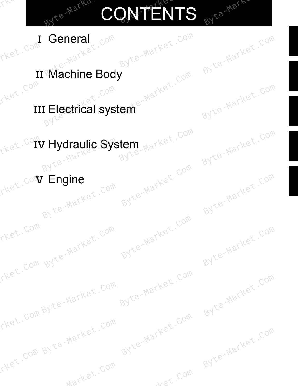
- WSM_KX36-3_41-3S_41-3V_Mechanism — p. 1
- CONTENTS — p. 3
- I. General — p. 4
- a. Sales feature — p. 5
- Product concept : Comfort in conpact — p. 5
- b. Difference between KX36-3 and KX41-3 — p. 5
- c. Quick chart for selling points : KX41-3V — p. 6
- d. Comparison to competitors;EU - version — p. 7
- e. New engineering feature — p. 8
- 1. Hydraulic system — p. 8
- 2. Improvement in user-friendliness and operator's range of vision — p. 9
- 3. Electronic System — p. 9
- f. Compornents compatibility — p. 10
- a. Sales feature — p. 5
- II. Machine Body — p. 12
- a. Quality Specifications — p. 13
- b. Main component — p. 17
- 1. Swivel bearing — p. 17
- 2. Track roller — p. 18
- 3. Idler and tension spring — p. 19
- 4. Pump coupling — p. 20
- 5. Rubber track — p. 21
- 6. Swing bracket — p. 22
- 7. Bucket link pin : North America & Oceanea — p. 23
- III. Electrical System — p. 24
- a. Development concept : KX41-3 — p. 25
- 1. Background of Adoption of New Meter — p. 25
- 2. Features of New Meter — p. 25
- 3. Electrical system : Functional comparison : KX41-3S, V — p. 27
- b. Outline of Kubota ICS (Intelligent Control System) — p. 28
- c. Operating Mode — p. 31
- 1. Outline — p. 31
- 2. LCD display list — p. 32
- d. Service mode menues — p. 35
- 1. Outline — p. 35
- 2. Service mode flow chart — p. 35
- 3. Main menues and functions — p. 36
- e. Failure Diagnosis — p. 57
- 1. Failure display and diagnosis criteria — p. 57
- 2. Fail record in EEPROM — p. 59
- 3. self-diagnosis of controller unit — p. 62
- 4. Electrical component layout — p. 68
- 5. Service Mode KX41-3(Non-AI Non- anti-theft Non-S/P) ver 1.13 — p. 69
- f. Circuit wiring diagram — p. 70
- 1. KX36-3 EU — p. 70
- 2. KX-41-3 Export (EU) (US) — p. 71
- 3. KX-41-3 Export standard type — p. 72
- 4. Main electrical compornents — p. 73
- 5. Covering circuit by controller — p. 74
- g. Electrical component — p. 76
- 1. Battery — p. 76
- 2. Fuel sensor — p. 76
- 3. Fuse box — p. 77
- 4. Heater : EU - version — p. 78
- a. Development concept : KX41-3 — p. 25
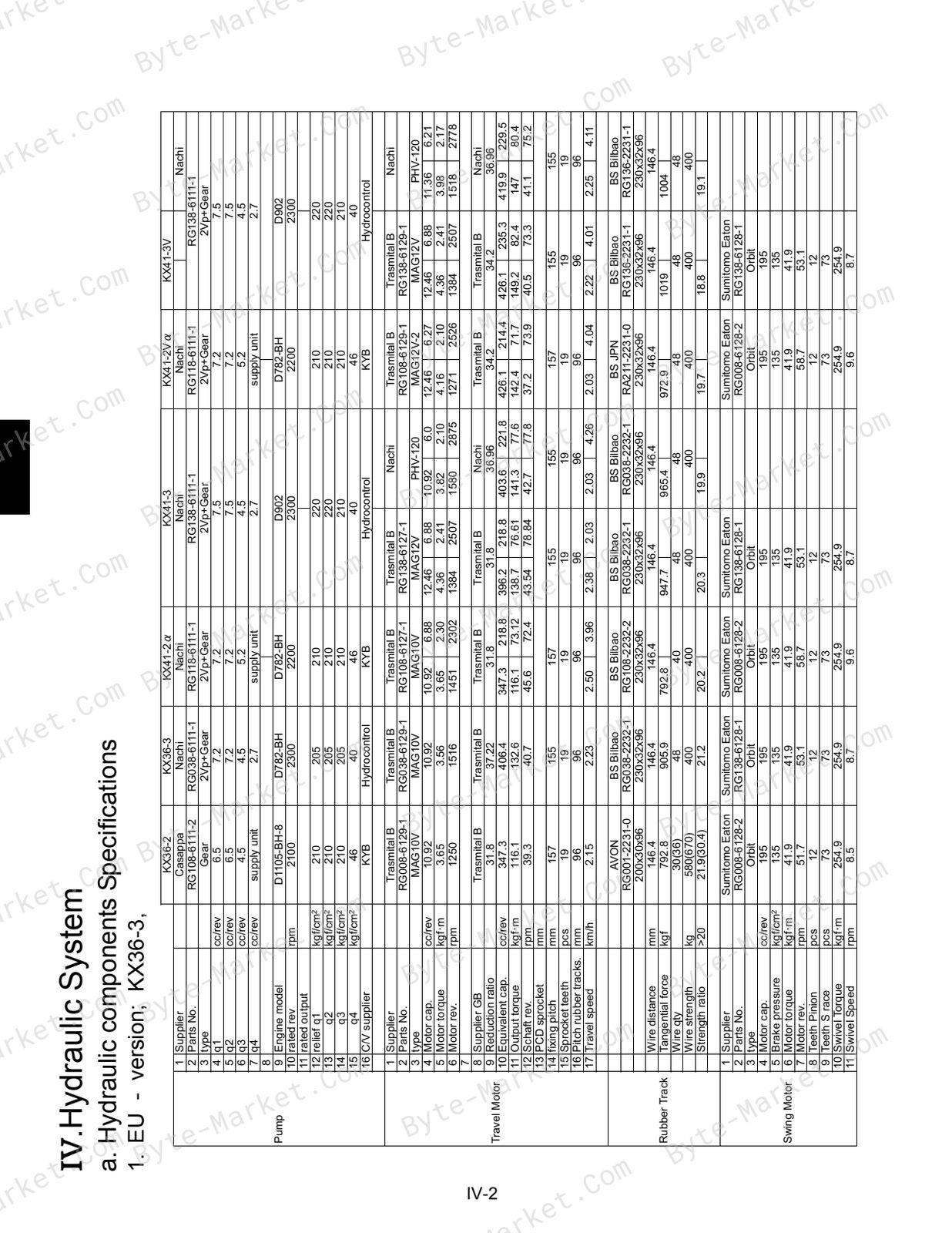
- IV. Hydraulic System — p. 80
- a. Hydraulic components Specifications — p. 81
- 1. EU - version; KX36-3, KX41-3, KX41-3V — p. 81
- 2. Cylinder Specifications; EU - version — p. 82
- b. Hydraulic circuit diagram — p. 84
- 1. KX36-3: EU - version — p. 84
- 2. KX41-3: EU - version — p. 85
- 3. KX41-3V: EU - version — p. 86
- 4. KX41-3V: North America & Oceania - version — p. 87
- c. Main pump — p. 88
- 1. Outer view — p. 88
- 2. structure — p. 89
- 3. P-Q performance curve — p. 90
- 4. Pump Specifications, Type : PVD-00B-15P-5G3-4982A — p. 90
- 5. Function1 — p. 91
- 6. Function2 — p. 91
- d. Control valve assy — p. 92
- 1. KX36-3: EU - version, Code No:RG038-61131, Maker: Hydro control — p. 92
- 2. KX41-3: EU - version, Code No:RG138-61131, Maker: Hydro control — p. 93
- 3. Control valve section : KX41-3S ; RG138-61131 — p. 94
- e. Pilot valve — p. 98
- 1. EU - version — p. 98
- f. Travel motor — p. 99
- 1. EU - version; KX36-3, KX41-3S, KX41-3V Maker: Transmital Bonfiglioli — p. 99
- 2. KTC, KCL, KTA - version : KX41-3V — p. 101
- 3. Structure — p. 102
- 4. Principle of operation — p. 103
- g. Swivel motor — p. 108
- 1. EU - version; KX36-3, KX41-3, KX41-3V Maker: Eaton Fluid Power Ltd. — p. 108
- h. Cylinder — p. 109
- 1. Structure — p. 109
- i. Rotary joint — p. 113
- 1. Structure — p. 113
- j. Unload valve — p. 116
- 1. North America and Oceanea version — p. 116
- 2. EU - version — p. 117
- k. Selector valve : KX41-3V — p. 118
- 1. Structure — p. 118
- 2. Function — p. 118
- 3. Specifications — p. 118
- l. Accessaries of hydraulic compornents — p. 119
- 1. Check valve assy — p. 119
- 2. Hydraulic filter — p. 119
- m. Service port performance — p. 120
- 1. Test sample : KX36-3 GL — p. 120
- 2. Test sample : KX41-3V GL — p. 121
- a. Hydraulic components Specifications — p. 81
- V. Engine — p. 122
- a. Engine Specifications — p. 124
- b. Performance curve — p. 126
- c. Function & structure of coil commander — p. 128
- 1. Circuit diagram — p. 128
- 2. Function — p. 128
- 3. Inspeetion & troubleshooting — p. 129
Capabilities
The source outline indexes servicing instructions, checking and adjustment, and troubleshooting. Use these source-backed headings to locate the applicable task or system in the source PDF, then confirm model-specific notes, specifications, illustrations, and operating conditions at the relevant page before carrying out service work.
Keep the source's safety sequence, prerequisite steps, labels, units, configuration notes, and footnotes with the selected task; do not apply an isolated value outside the conditions stated in the manual.
Technical reference
Reference tables include pressure specifications for service checks, adjustment work, and specification lookup. Use the values and conditions in the PDF for the applicable model and procedure.
- Pressure reference: pressure specifications.
Delivery
This manual is supplied as a digital PDF file and is available for instant download after purchase. No physical media is shipped.
References
Kubota Workshop Manual for Excavator, document code 97899-60810, PDF edition.


No questions found.