
Kubota MECHANIC’S DAILY SERVICE AID Manual
Kubota RY920-2367-3-MDA Manual
Document number RY920-2367-3 · English PDF edition · 126 pages
About this manual
Kubota published this Workshop Manual for the RY920-2367-3-MDA wheel loader models. It brings the documented service and technical-reference material for those named wheel loaders into a single publication.
Use the Manual Contents below to check that the exact repair, inspection, or maintenance procedure you need is included in this publication.
Manual details
- Manufacturer
- Kubota
- Manual type
- MDA Manual
- Models
- R065, R085, R082, R070, R090
- Document number
- RY920-2367-3
- Language
- English
- Page count
- 126
Product highlights
Electrical systems
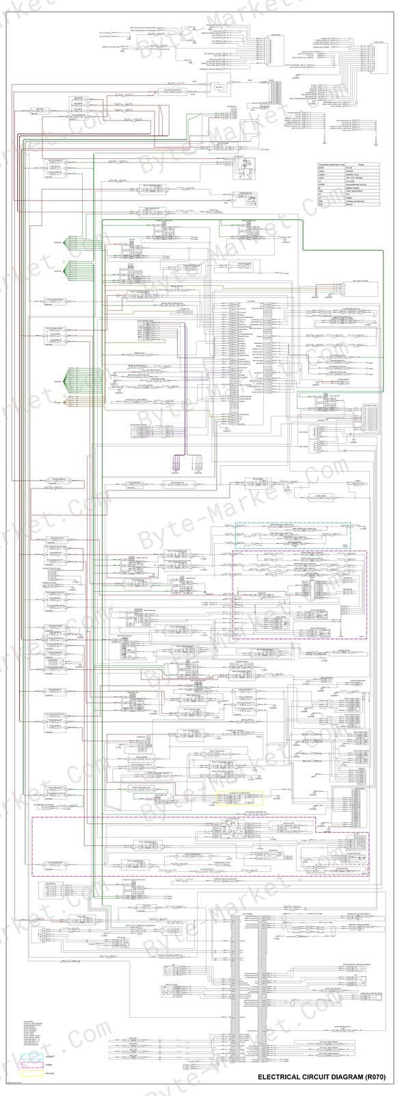
The manual includes wiring diagrams, connector views, and pinouts.
Hydraulic systems
The manual includes hydraulic circuit diagrams and hydraulic pressure-test material.
Maintenance
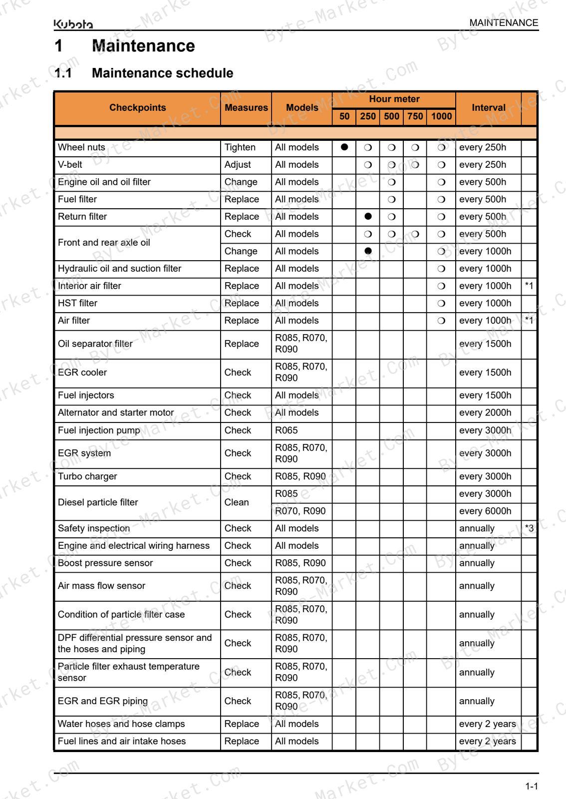
The manual includes a maintenance schedule and a lubrication chart.
Manual contents
Use these source headings to locate the task or system you need in the PDF.
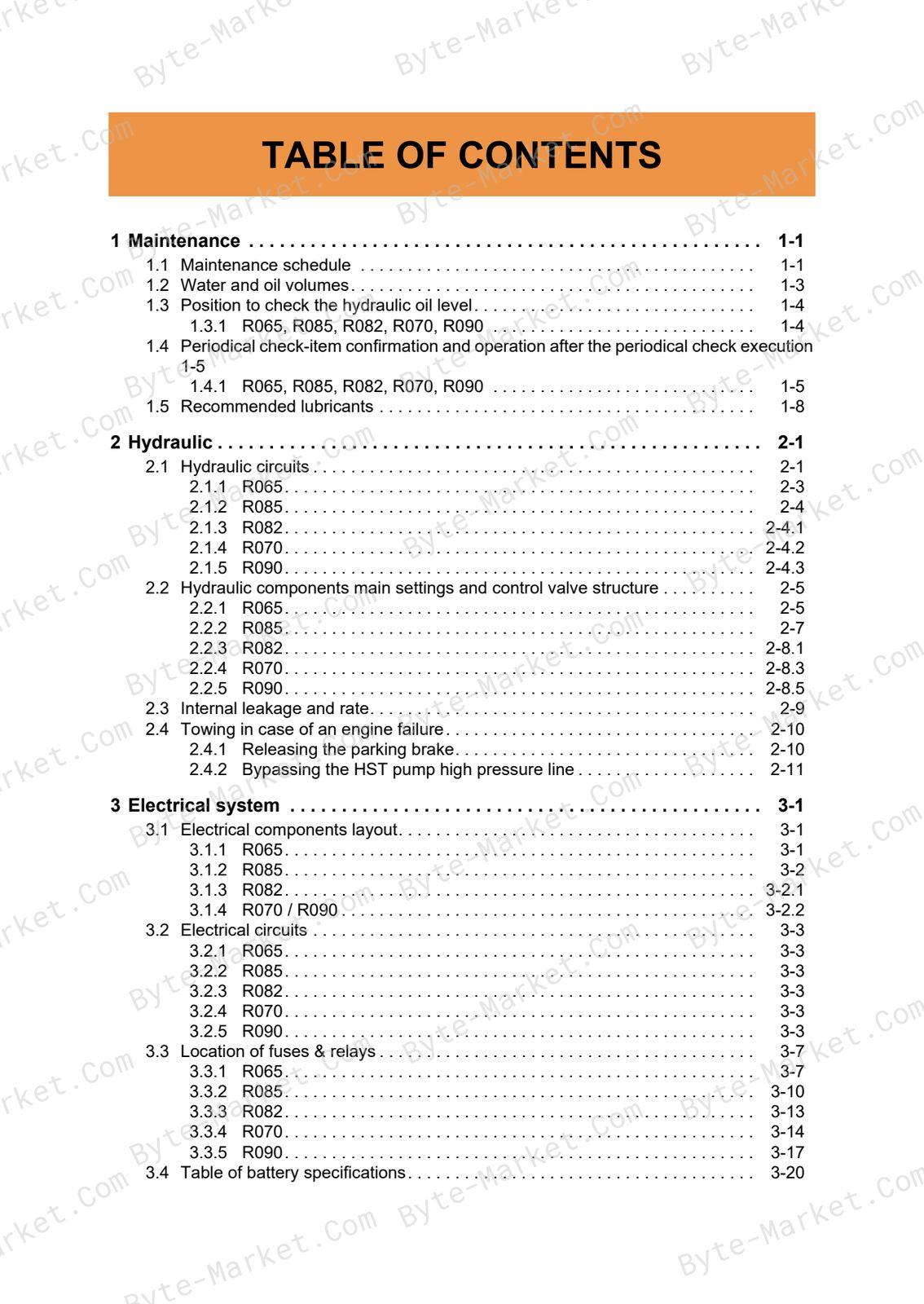
- TABLE OF CONTENTS — p. 2
- Revision history — p. 4
- 1 Maintenance — p. 6
- 1.1 Maintenance schedule — p. 6
- 1.2 Water and oil volumes — p. 8
- 1.3 Position to check the hydraulic oil level — p. 9
- 1.3.1 R065, R085, R082, R070, R090 — p. 9
- 1.4 Periodical check-item confirmation and operation after the periodical check execution — p. 10
- 1.4.1 R065, R085, R082, R070, R090 — p. 10
- 1. Turn the key switch to the RUN position. — p. 10
- 2. Pressing SW1 switches from the normal mode to the user settings mode. — p. 10
- 3. Pressing SW2 toggles the items displayed on the LCD screen in a loop. — p. 10
- 1.4.1 R065, R085, R082, R070, R090 — p. 10
- 1.5 Recommended lubricants — p. 13
- 2 Hydraulic — p. 14
- 2.1 Hydraulic circuits — p. 14
- 2.1.1 R065 — p. 16
- 2.1.2 R085 — p. 17
- 2.1.3 R082 — p. 18
- 2.1.4 R070 — p. 19
- 2.1.5 R090 — p. 20
- 2.2 Hydraulic components main settings and control valve structure — p. 22
- 2.2.1 R065 — p. 22
- 2.2.2 R085 — p. 24
- 2.2.3 R082 — p. 26
- 2.2.4 R070 — p. 28
- 2.2.5 R090 — p. 30
- 2.3 Internal leakage and rate — p. 32
- 2.4 Towing in case of an engine failure — p. 33
- 2.4.1 Releasing the parking brake — p. 33
- 2.4.2 Bypassing the HST pump high pressure line — p. 34
- 2.1 Hydraulic circuits — p. 14
- 3 Electrical system — p. 36
- 3.1 Electrical components layout — p. 36
- 3.1.1 R065 — p. 36
- 3.1.2 R085 — p. 37
- 3.1.3 R082 — p. 38
- 3.1.4 R070 / R090 — p. 39
- 3.2 Electrical circuits — p. 40
- 3.2.1 R065 — p. 42
- 3.2.2 R085 — p. 44
- 3.2.3 R082 — p. 46
- 3.2.4 R070 — p. 48
- 3.2.5 R090 — p. 50
- 3.3 Location of fuses & relays — p. 52
- 3.3.1 R065 — p. 52
- 3.3.2 R085 — p. 55
- 3.3.3 R082 — p. 58
- 3.3.4 R070 — p. 61
- 3.3.5 R090 — p. 64
- 3.4 Table of battery specifications — p. 67
- 3.1 Electrical components layout — p. 36
- 4 Digital meter panel setting mode — p. 68
- 4.1 User setting mode — p. 68
- 4.1.1 R065 — p. 68
- 4.1.2 R082, R085 — p. 69
- 4.1.3 R070, R090 — p. 70
- 4.2 Dealer setting mode — p. 72
- 4.2.1 R065, R082, R085 — p. 72
- 4.2.2 R070, R090 — p. 75
- 4.2.3 Service mode settings - R065, R082, R085 — p. 78
- 4.2.4 Service mode settings - R070, R090 — p. 81
- 4.3 Error codes — p. 85
- 4.3.1 R065 — p. 85
- 4.3.2 R085 — p. 88
- 4.3.3 R082 — p. 94
- 4.3.4 R070, R090 — p. 97
- 4.3.5 Diesel Particle Filter (DPF) regeneration - Conditions and procedures — p. 102
- 4.1 User setting mode — p. 68
- 5 Miscellaneous, Engine — p. 108
- 5.1 AUX lines — p. 108
- 5.1.1 AUX flow rate R065 — p. 108
- 5.1.2 AUX flow rate R085 — p. 108
- 5.1.3 AUX flow rate R082 — p. 109
- 5.1.4 AUX port positions — p. 110
- 5.2 Wheels — p. 110
- 5.2.1 Tire pressure for different tires and pallet fork/bucket R065 up to #00278 — p. 110
- 5.2.2 Tire pressure for different tires and pallet fork/bucket R065HW as of #00279 — p. 111
- 5.2.3 Tire pressure for different tires and pallet fork/bucket R085 — p. 111
- 5.2.4 Tire pressure for different tires and pallet fork/bucket R082 — p. 111
- 5.2.5 Tire pressure for different tires and pallet fork/bucket R070 — p. 111
- 5.2.6 Tire pressure for different tires and pallet fork/bucket R090 — p. 111
- 5.3 Engine basic data — p. 112
- 5.4 A/C pressure switch — p. 112
- 5.5 Center pin play — p. 113
- 5.1 AUX lines — p. 108
- 6 Tightening torques — p. 114
- 6.1 General tightening torques — p. 114
- 6.1.1 Stud bolts — p. 114
- 6.1.2 Torque for hydraulic hose fittings — p. 115
- 6.1.3 Torques of lock nuts for elbows with male seats and adaptors with O-rings (Straight Threads) — p. 115
- 6.2 Specific tightening torques — p. 116
- 6.3 Torque conversion chart N·m to lbf·ft — p. 117
- 6.1 General tightening torques — p. 114
- 7 Annex 1 - Inspection sheets — p. 118
Capabilities
The source outline indexes maintenance tasks, checking and adjustment, and servicing instructions. Use these source-backed headings to locate the applicable task or system in the source PDF, then confirm model-specific notes, specifications, illustrations, and operating conditions at the relevant page before carrying out service work.
Keep the source's safety sequence, prerequisite steps, labels, units, configuration notes, and footnotes with the selected task; do not apply an isolated value outside the conditions stated in the manual.
Technical reference
Reference tables include maintenance schedules and checklists, limits and settings, electrical specifications, and tightening torques for service checks, adjustment work, and specification lookup. Use the values and conditions in the PDF for the applicable model and procedure.
- Service limits and settings: tightening torques and limits and settings.
- Electrical and emissions: electrical specifications.
- Service planning: maintenance schedules and checklists.
Delivery
This manual is supplied as a digital PDF file and is available for instant download after purchase. No physical media is shipped.
References
Kubota Workshop Manual for Wheel Loader, document code RY920-2367-3, PDF edition.


No questions found.