
Kubota Workshop Manual
Kubota R420α and R520α Workshop Manual
Document number 97899-60790 · English PDF edition · 75 pages
About this manual
Kubota published this Workshop Manual for the R420α and R520α wheel loader models. It brings the documented service and technical-reference material for those named wheel loaders into a single publication.
Use the Manual Contents below to check that the exact repair, inspection, or maintenance procedure you need is included in this publication.
Manual details
- Manufacturer
- Kubota
- Manual type
- Workshop Manual
- Models
- R420α and R520α
- Document number
- 97899-60790
- Publication year
- 2012
- Language
- English
- Page count
- 75
Product highlights
Electrical systems
The manual includes wiring diagrams.
Hydraulic systems
The manual includes hydraulic circuit diagrams.
Specifications and settings
The manual includes reference information for pressure specifications.
Manual contents
Use these source headings to locate the task or system you need in the PDF.
- 1. General — p. 4
- [1] Machine specifications — p. 4
- (1) Specification table(1) — p. 4
- (2) Specification table(2), Backhoe-version — p. 5
- (3) Lifting capacity — p. 6
- [2] Development concept of model change — p. 7
- (1) Two main concepts — p. 7
- (2) Product feature — p. 7
- (3) Looks and design renewal — p. 11
- (4) Attachments and regulation — p. 11
- (5) Quality improvement, main points — p. 12
- (6) Quality improvement; Improved startup acceleration — p. 14
- (7) Quality improvement; Bucket dump angle — p. 15
- (8) Quality improvement; Maneuverability — p. 16
- (9) Quality improvement; Durability & reliability — p. 17
- (10) Quality improvement; Operator comfort, Travelling noise reduction — p. 18
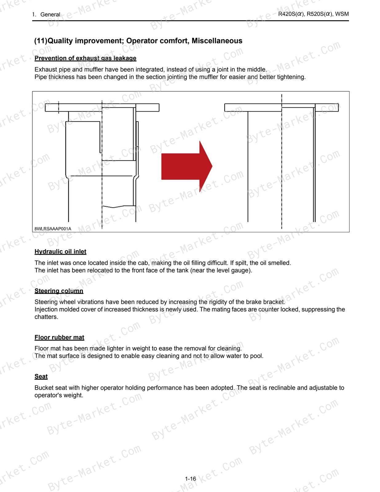
- (11) Quality improvement; Operator comfort, Miscellaneous — p. 19
- (12) Prevention of oil leakage from axle shaft — p. 20
- [3] Quality specifications; R420S, R520S — p. 21
- [1] Machine specifications — p. 4
- 2. Machine Body & Front Attachment — p. 25
- [1] Front attachment — p. 25
- [2] Frame articulation and center pin — p. 26
- 3. Engine — p. 27
- [1] Engine specifications — p. 27
- [2] Engine performance curve — p. 29
- 4. Hydraulic System — p. 31
- [1] Circuit diagram & components — p. 31
- (1) Hydraulic circuit diagram — p. 31
- (2) Components'layout — p. 33
- (3) Backhoe circuit diagram — p. 34
- [2] LST pump — p. 35
- (1) Function of LST pump (A4V pump) — p. 35
- (2) Servo cylinder (DA regulator) — p. 37
- (3) High-pressure relief valve — p. 39
- (4) Low pressure relief valve (Charge relief valve) — p. 40
- (5) Automatic shift function — p. 41
- (6) Torque control function — p. 41
- (7) Inclined rotation resetting force and advance angle — p. 42
- (8) LST pump orifice — p. 43
- (9) DA valve (speed relay valve) — p. 44
- (10) Function of DA valve — p. 45
- (11) Bypassing the looped line — p. 48
- (12) Improvement of temperature characteristics of LST system — p. 49
- [3] LST motor — p. 50
- (1) Series comparison — p. 50
- (2) LST motor structure — p. 51
- (3) LST motor diagram — p. 52
- (4) LST motor, oil flow — p. 53
- (5) LST motor mechanism — p. 55
- (6) LST motor servo-regulator — p. 56
- (7) LST motor servo-regulator — p. 58
- (8) Theory — p. 61
- (9) LST system diagram — p. 62
- [4] Steering system — p. 63
- (1) Steering unit — p. 63
- (2) Steering unit diagram — p. 63
- [1] Circuit diagram & components — p. 31
- 5. Brake control system — p. 65
- [1] Outline — p. 65
- [2] Parking brake — p. 66
- [3] Service brake: Axle brake (EU-version) — p. 68
- [4] Negative brake releasing method — p. 70
- 6. Electrical System — p. 72
- [1] Electrical wiring — p. 72
- [2] Electrical circuit diagram — p. 73
Capabilities
The source outline indexes mechanism explanations and servicing instructions. Use these source-backed headings to locate the applicable task or system in the source PDF, then confirm model-specific notes, specifications, illustrations, and operating conditions at the relevant page before carrying out service work.
Keep the source's safety sequence, prerequisite steps, labels, units, configuration notes, and footnotes with the selected task; do not apply an isolated value outside the conditions stated in the manual.
Technical reference
Reference tables include pressure specifications for service checks, adjustment work, and specification lookup. Use the values and conditions in the PDF for the applicable model and procedure.
- Pressure reference: pressure specifications.
Delivery
This manual is supplied as a digital PDF file and is available for instant download after purchase. No physical media is shipped.
References
Kubota Workshop Manual for Wheel Loader, document code 97899-60790, PDF edition.


No questions found.