
Kubota Service Manual
Kubota RT210-2E and RT220-2E Service Manual
Document number TOB-0087051 · English PDF edition · 243 pages
About this manual
Kubota published this Service Manual for RT210-2E and RT220-2E. It is intended for maintenance, source-supported service, and source-supported repair, where those subjects appear in the source publication.
Use the Manual Contents below to check that the exact maintenance, inspection, service, or repair procedure you need is included in this publication.
Manual details
- Manufacturer
- Kubota
- Manual type
- Service Manual
- Models
- RT210-2E and RT220-2E
- Document number
- TOB-0087051
- Publication year
- 2023
- Language
- English
- Page count
- 243
Product highlights
Electrical systems
The manual includes wiring diagrams and electrical troubleshooting.
Hydraulic systems
The manual includes hydraulic circuit diagrams.
Diagnostics
The manual includes diagnostic trouble-code reference information and sensor-testing information.
Specifications and settings
The manual includes reference information for pressure specifications.
Special tools
A special-tools section is included.
Manual contents
Use these source headings to locate the task or system you need in the PDF.
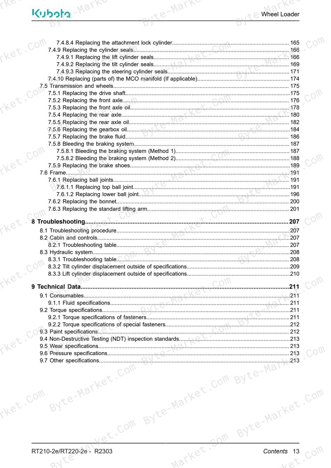
- Preface — p. 3
- Language — p. 3
- Related documents — p. 4
- OEM documentation overview — p. 4
- Icons and signal words used in the document — p. 4
- Tools — p. 5
- Illustrations — p. 5
- Version history — p. 5
- Typographical conventions — p. 6
- Abbreviations — p. 6
- Terminology — p. 7
- 1 Safety — p. 15
- 1.1 Service-related safety instructions — p. 15
- 1.1.1 General safety instructions — p. 15
- 1.1.2 Safety instructions for service on the transmission — p. 15
- 1.1.3 Safety instructions for service below the lifting arm — p. 15
- 1.2 Battery safety — p. 16
- 1.3 Disconnecting the battery — p. 17
- 1.4 Approved trainer — p. 18
- 1.5 Approved service engineer — p. 18
- 1.1 Service-related safety instructions — p. 15
- 2 Description — p. 19
- 2.1 Electrical system — p. 19
- 2.1.1 Schematic overview — p. 19
- 2.1.2 Electrical diagram — p. 19
- 2.1.3 DCU (Display Control Unit) — p. 20
- 2.1.4 MCU (Machine Control Unit) — p. 20
- 2.1.5 DC-DC converter — p. 21
- 2.1.6 Power controller — p. 21
- 2.1.7 TLC (Traffic Light Controller) — p. 22
- 2.1.8 CAN (Control Area Network) isolator — p. 22
- 2.1.9 Battery and internal charger — p. 23
- 2.1.10 MFC (Multi-Function Controller) — p. 23
- 2.1.11 FCM (Function Control Module) — p. 24
- 2.1.12 Termination resistors — p. 25
- 2.1.13 Fuses and relays — p. 25
- 2.1.13.1 Fuse box 1 — p. 26
- 2.1.13.2 Fuse box 2 (If applicable) — p. 28
- 2.1.13.3 Fuse box 3 (If applicable) — p. 29
- 2.1.13.4 Main contactor — p. 30
- 2.1.14 Ground connections — p. 30
- 2.1.15 High power connections — p. 32
- 2.1.16 Electric motors — p. 34
- 2.1.17 Diagnostic connector — p. 35
- 2.1.18 Service Tool — p. 36
- 2.2 Hydraulic system — p. 36
- 2.2.1 Hydraulic diagram — p. 36
- 2.2.2 Overview of the steering hydraulics — p. 37
- 2.2.3 Overview of the work hydraulics — p. 38
- 2.2.4 Work pump — p. 39
- 2.2.5 Main control valve — p. 39
- 2.2.6 Hydraulic cylinders — p. 41
- 2.2.6.1 Tilt and lift cylinders — p. 41
- 2.2.6.2 Steering cylinder — p. 42
- 2.2.6.3 Attachment lock cylinder — p. 42
- 2.2.7 Steering unit — p. 43
- 2.2.8 6/2-diverter valve (If applicable) — p. 44
- 2.3 Transmission and wheels — p. 45
- 2.3.1 Overview — p. 45
- 2.3.2 Brake and inching system — p. 46
- 2.1 Electrical system — p. 19
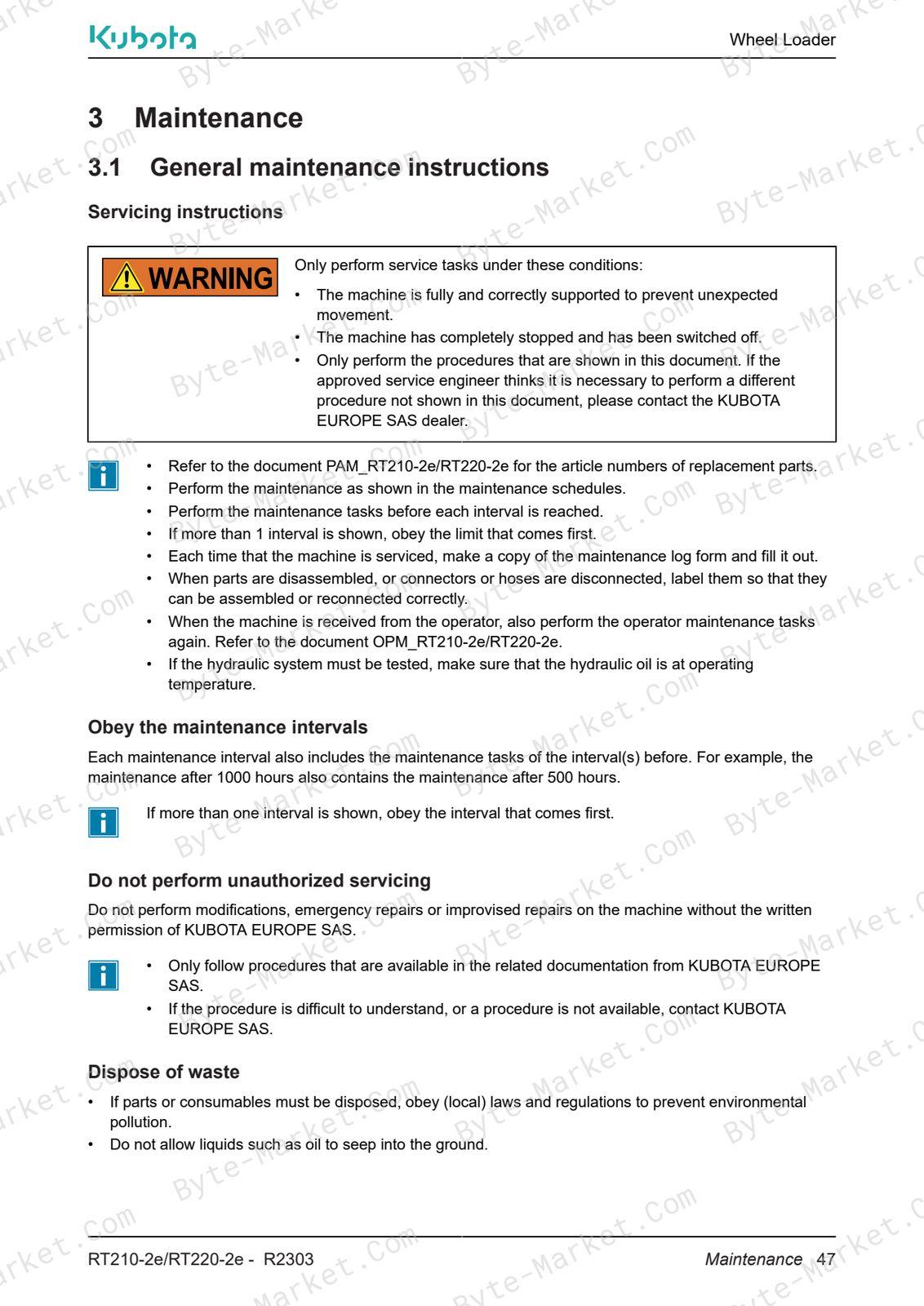
- 3 Maintenance — p. 47
- 3.1 General maintenance instructions — p. 47
- 3.2 Performing a test drive — p. 48
- 3.3 Ordering parts — p. 48
- 3.4 Servicing below the lifting arm — p. 48
- 3.4.1 Installing the safety bracket — p. 48
- 3.4.2 Storing the safety bracket — p. 49
- 3.5 Accessing parts — p. 50
- 3.5.1 Opening the bonnet — p. 50
- 3.5.2 Tilting the driver's seat — p. 50
- 3.5.3 Accessing the steering unit — p. 51
- 3.5.4 Accessing the brakes — p. 52
- 3.6 Panolin synthetic hydraulic oil (If applicable) — p. 52
- 3.6.1 Requirements — p. 53
- 3.6.2 Sample method — p. 53
- 3.6.3 Test intervals — p. 54
- 3.7 Maintenance schedules — p. 54
- 3.7.1 Maintenance: quick reference — p. 54
- 3.7.2 Maintenance before delivery — p. 56
- 3.7.3 Maintenance after the first 50 hours — p. 59
- 3.7.4 Maintenance every 50 hours — p. 60
- 3.7.5 Maintenance every 500 hours — p. 60
- 3.7.6 Maintenance every 1000 hours — p. 62
- 3.7.7 Maintenance every 1 year — p. 62
- 3.8 Maintenance tasks — p. 64
- 3.8.1 Electric motors — p. 64
- 3.8.2 Hydraulic system — p. 65
- 3.8.3 Electrical system — p. 65
- 3.8.4 Cabin and controls — p. 66
- 3.8.5 Transmission and wheels — p. 68
- 3.8.6 Frame — p. 69
- 4 Checks, cleaning and functional tests — p. 71
- 4.1 Cabin and controls — p. 71
- 4.1.1 Checking the ROPS-FOPS structure — p. 71
- 4.1.2 Checking the windscreen wiper blades (If applicable) — p. 72
- 4.1.3 Testing the steering system — p. 72
- 4.1.4 Checking the steering wheel — p. 72
- 4.1.5 Testing the steering column — p. 72
- 4.1.6 Checking the steering column lock — p. 72
- 4.1.7 Testing the radio (If applicable) — p. 72
- 4.1.8 Testing the driver's seat — p. 73
- 4.1.9 Testing the 12-V connection (If applicable) — p. 73
- 4.1.10 Testing the rotating beacon (If applicable) — p. 73
- 4.1.11 Testing the heater (If applicable) — p. 73
- 4.1.12 Checking OPM (operator manual) presence — p. 73
- 4.1.13 Checking the cabin/canopy vibration dampers — p. 74
- 4.2 Electric motors — p. 75
- 4.2.1 Checking the cable connectors — p. 75
- 4.2.2 Checking the vibration dampers — p. 76
- 4.2.3 Checking the drive motor cooling fan — p. 77
- 4.3 Electrical system — p. 77
- 4.3.1 Checking the electrical wiring — p. 77
- 4.3.2 Checking the DTCs — p. 78
- 4.3.3 Checking the software version of the DCU/MCU — p. 78
- 4.3.4 Checking the power controller cooling fan — p. 79
- 4.4 Hydraulic system — p. 80
- 4.4.1 Checking the hydraulic cylinder scraper — p. 80
- 4.4.2 Testing the cylinder seals — p. 80
- 4.4.3 Testing the lifting arm displacements — p. 81
- 4.5 Transmission and wheels — p. 82
- 4.5.1 Checking the front axle oil level — p. 82
- 4.5.2 Checking the rear axle oil level — p. 83
- 4.5.3 Cleaning the axle breather plugs — p. 84
- 4.5.4 Checking gearbox oil level — p. 84
- 4.5.5 Testing the braking system — p. 85
- 4.6 Frame — p. 85
- 4.6.1 Checking the paintwork — p. 85
- 4.6.2 Checking the attachment lock position — p. 85
- 4.6.3 Checking the hinge pin bolts and spring pins — p. 87
- 4.1 Cabin and controls — p. 71
- 5 Measurements — p. 89
- 5.1 Cabin and controls — p. 89
- 5.1.1 Measuring the front automotive lights inclination — p. 89
- 5.2 Electrical system — p. 90
- 5.2.1 Measuring battery voltage — p. 90
- 5.2.2 Measuring output voltage of the DC-DC converter — p. 91
- 5.3 Hydraulic system — p. 92
- 5.3.1 Measuring the main work pressure — p. 92
- 5.3.1.1 Measuring the main work pressure (With pressure gauge) — p. 92
- 5.3.1.2 Measuring the main work pressure (With service tool) — p. 93
- 5.3.1 Measuring the main work pressure — p. 92
- 5.4 Measuring the steering pressure — p. 94
- 5.5 Transmission and wheels — p. 95
- 5.5.1 Measuring the brake shoes wear — p. 95
- 5.1 Cabin and controls — p. 89
- 6 Adjustments — p. 97
- 6.1 Cabin and controls — p. 97
- 6.1.1 Adjusting the front automotive lights inclination — p. 97
- 6.2 Electrical system — p. 97
- 6.2.1 Charging the battery — p. 97
- 6.2.2 Updating the software of a specific control unit — p. 98
- 6.2.3 Updating the MFC software — p. 99
- 6.2.4 Updating the power controller software — p. 100
- 6.2.5 Calibrating the drive pedal — p. 101
- 6.2.6 Calibrating the spool stroke sensors — p. 102
- 6.3 Hydraulic system — p. 103
- 6.3.1 Adjusting the main work pressure — p. 103
- 6.3.2 Adjusting the tilt cylinder load-holding valve — p. 104
- 6.3.3 Adjusting the lift cylinder load-holding valve — p. 105
- 6.4 Transmission and wheels — p. 106
- 6.4.1 Adding oil to the front axle — p. 106
- 6.4.2 Adding oil to the rear axle — p. 107
- 6.4.3 Adding oil to the gearbox — p. 108
- 6.1 Cabin and controls — p. 97
- 7 Replacements — p. 109
- 7.1 Cabin and controls — p. 109
- 7.1.1 Replacing the safety roof — p. 109
- 7.1.1.1 Replacing the canopy — p. 109
- 7.1.1.2 Replacing the cabin — p. 112
- 7.1.1.3 Replacing the foldable roof — p. 116
- 7.1.2 Replacing the steering wheel — p. 118
- 7.1.3 Replacing the steering column — p. 119
- 7.1.4 Replacing the DCU — p. 120
- 7.1.5 Replacing the switch panels — p. 121
- 7.1.5.1 Switch panel in steering column — p. 121
- 7.1.5.2 Replacing the rear right switch panel — p. 122
- 7.1.6 Replacing the driver's seat — p. 123
- 7.1.7 Replacing the windscreen wiper blades (If applicable) — p. 124
- 7.1.8 Replacing the radio (If applicable) — p. 124
- 7.1.9 Replacing the joystick — p. 124
- 7.1.1 Replacing the safety roof — p. 109
- 7.2 Electric motors — p. 126
- 7.2.1 Replacing the drive motor — p. 126
- 7.2.2 Replacing the drive motor parking brake — p. 129
- 7.2.3 Replacing the drive motor cooling fan — p. 131
- 7.2.4 Replacing the work motor — p. 132
- 7.2.5 Replacing the speed sensor — p. 134
- 7.3 Electrical system — p. 135
- 7.3.1 Replacing the battery — p. 135
- 7.3.2 Replacing the internal battery charger — p. 140
- 7.3.3 Replacing the main contactor — p. 142
- 7.3.4 Replacing the DC-DC converter — p. 144
- 7.3.5 Replacing the MCU — p. 146
- 7.3.6 Replacing the MFC — p. 147
- 7.3.7 Replacing the power controller — p. 149
- 7.3.8 Replacing the power controller cooling fan — p. 151
- 7.4 Hydraulic system — p. 152
- 7.4.1 Replacing the hydraulic oil — p. 152
- 7.4.2 Replacing the complete hydraulic filter — p. 154
- 7.4.3 Replacing the hydraulic oil tank filler cap — p. 155
- 7.4.4 Replacing the work pump — p. 155
- 7.4.5 Replacing the steering unit — p. 157
- 7.4.6 Replacing the main control valve — p. 159
- 7.4.7 Replacing the hydraulic hoses — p. 161
- 7.4.8 Replacing the hydraulic cylinders — p. 162
- 7.4.8.1 Replacing the lift cylinder — p. 162
- 7.4.8.2 Replacing the tilt cylinder — p. 163
- 7.4.8.3 Replacing the steering cylinder — p. 164
- 7.4.8.4 Replacing the attachment lock cylinder — p. 165
- 7.4.9 Replacing the cylinder seals — p. 166
- 7.4.9.1 Replacing the lift cylinder seals — p. 166
- 7.4.9.2 Replacing the tilt cylinder seals — p. 169
- 7.4.9.3 Replacing the steering cylinder seals — p. 171
- 7.4.10 Replacing (parts of) the MCO manifold (If applicable) — p. 174
- 7.5 Transmission and wheels — p. 175
- 7.5.1 Replacing the drive shaft — p. 175
- 7.5.2 Replacing the front axle — p. 176
- 7.5.3 Replacing the front axle oil — p. 178
- 7.5.4 Replacing the rear axle — p. 180
- 7.5.5 Replacing the rear axle oil — p. 182
- 7.5.6 Replacing the gearbox oil — p. 184
- 7.5.7 Replacing the brake fluid — p. 186
- 7.5.8 Bleeding the braking system — p. 187
- 7.5.8.1 Bleeding the braking system (Method 1) — p. 187
- 7.5.8.2 Bleeding the braking system (Method 2) — p. 188
- 7.5.9 Replacing the brake shoes — p. 189
- 7.6 Frame — p. 191
- 7.6.1 Replacing ball joints — p. 191
- 7.6.1.1 Replacing top ball joint — p. 191
- 7.6.1.2 Replacing lower ball joint — p. 196
- 7.6.2 Replacing the bonnet — p. 200
- 7.6.3 Replacing the standard lifting arm — p. 201
- 7.6.1 Replacing ball joints — p. 191
- 7.1 Cabin and controls — p. 109
- 8 Troubleshooting — p. 207
- 8.1 Troubleshooting procedure — p. 207
- 8.2 Cabin and controls — p. 207
- 8.2.1 Troubleshooting table — p. 207
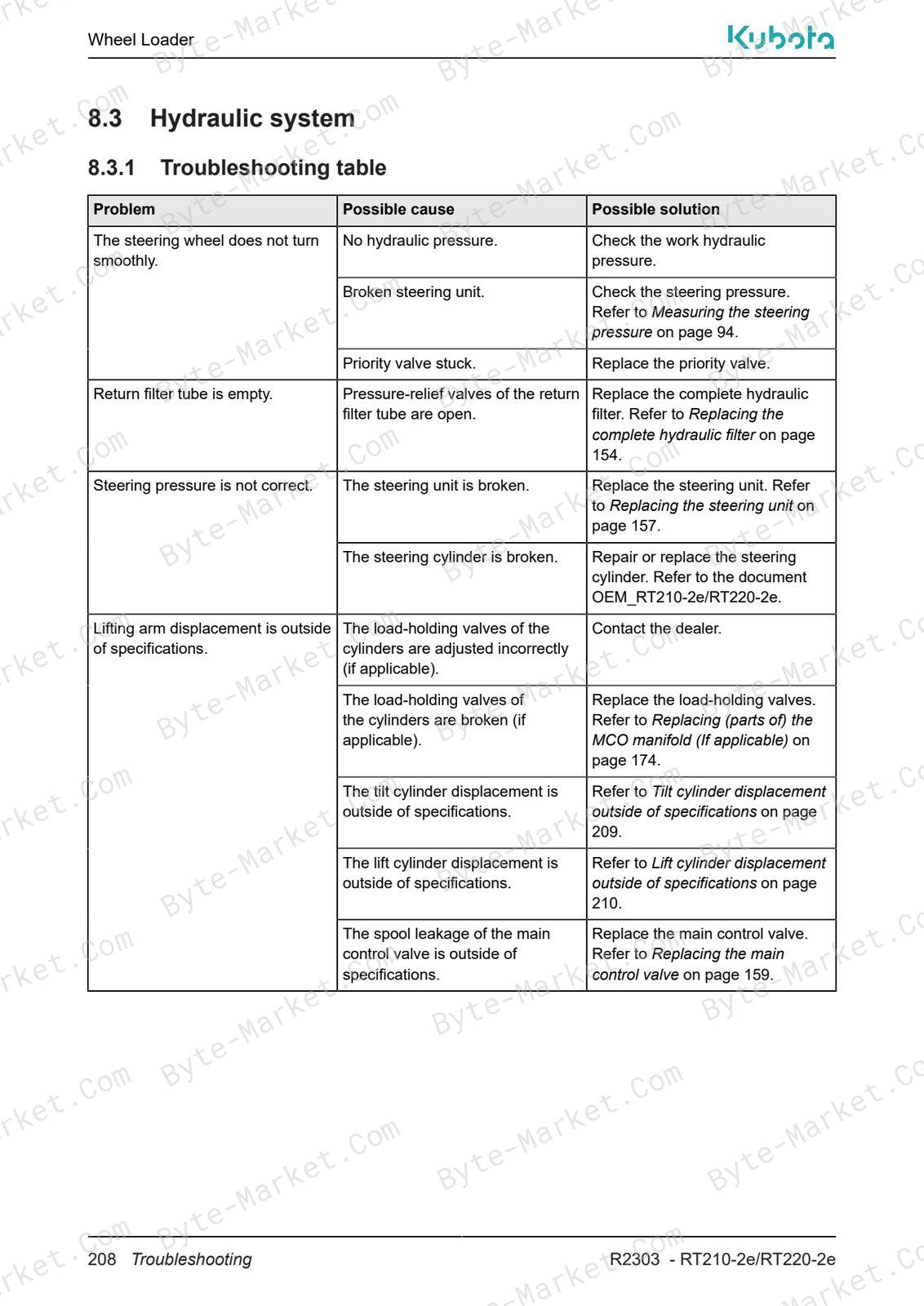
- 8.3 Hydraulic system — p. 208
- 8.3.1 Troubleshooting table — p. 208
- 8.3.2 Tilt cylinder displacement outside of specifications — p. 209
- 8.3.3 Lift cylinder displacement outside of specifications — p. 210
- 9 Technical Data — p. 211
- 9.1 Consumables — p. 211
- 9.1.1 Fluid specifications — p. 211
- 9.2 Torque specifications — p. 211
- 9.2.1 Torque specifications of fasteners — p. 211
- 9.2.2 Torque specifications of special fasteners — p. 212
- 9.3 Paint specifications — p. 212
- 9.4 Non-Destructive Testing (NDT) inspection standards — p. 213
- 9.5 Wear specifications — p. 213
- 9.6 Pressure specifications — p. 213
- 9.7 Other specifications — p. 213
- 9.1 Consumables — p. 211
Capabilities
The source outline indexes servicing instructions, maintenance, checking and adjustment, replacement procedures, troubleshooting, and inspection. Use these source-backed headings to locate the applicable service or repair topic in the source PDF, then confirm model-specific notes, specifications, illustrations, and operating conditions at the relevant page before carrying out service or repair work.
Keep the source's safety sequence, prerequisite steps, labels, units, configuration notes, and footnotes with the selected task; do not apply an isolated value outside the conditions stated in the manual.
Technical reference
Reference tables include pressure specifications for service specifications, limits, adjustment and repair reference data. Use the values and conditions in the PDF for the applicable model and procedure.
- Pressure reference: pressure specifications.
Delivery
This manual is supplied as a digital PDF file and is available for instant download after purchase. No physical media is shipped.
References
Kubota Service Manual for Wheel Loader, document code TOB-0087051, PDF edition.


No questions found.