
Kubota SVL95-2S Workshop Manual — RY911-23872
Overview
This Kubota SVL95-2S Workshop Manual — RY911-23872 is the 526-page, model-specific PDF reference for the listed compact track loader equipment.
For service preparation and technical reference, the publication keeps its source-backed system coverage, demonstrated work types, and detailed manual navigation in separate sections below.
Manual Details
- Manufacturer
- Kubota
- Manual type
- Workshop Manual
- Models
- SVL95-2S
- Equipment type
- Compact Track Loader
- Document number
- RY911-23872
- Publication / year
- 2018
- Pages
- 526
- Language
- English
- Format
Technical Coverage
- Engine and fuel-related systems
- Hydraulic circuits and control components
- Electrical systems, wiring and connector reference
- Powertrain and drive components
- Machine assemblies and work equipment
Service & Diagnostic Procedures
- Scheduled maintenance work
- Troubleshooting and fault isolation
- Inspection, testing and measurement checks
- Adjustment and specification-setting work
- Component removal and installation
Manual Contents
- SVL95-2s(p. 1)
- CONTENTS(p. 5)
- 1. INFORMATION(p. 18)
- SAFETY FIRST(p. 19)
- 1. In the interest of work safety(p. 20)
- 1.1 Precautions before working on the equipment(p. 20)
- 1.2 Be ready for an emergency(p. 20)
- 1.3 Precautions before working on the equipment(p. 21)
- 1.4 Starting the machine safely(p. 21)
- 1.5 Keep away from fire(p. 22)
- 1.6 Processing waste liquid(p. 22)
- 2. Safety labels(p. 23)
- 2.1 Affixing positions of safety labels(p. 23)
- 2.2 Maintenance of safety labels(p. 27)
- 2. GENERAL(p. 28)
- WORK PRECAUTIONS(p. 29)
- 1. General work(p. 29)
- 1.1 Using plumber's tape(p. 29)
- 1.2 Replacing O-rings(p. 29)
- 1.3 Replacing the oil seal(p. 29)
- 1.4 Replacing the floating seal(p. 30)
- 1.5 Assemble the snap ring(p. 30)
- 1.6 How to insert a spring pin(p. 30)
- 1.7 Apply threadlock.(p. 30)
- 1.8 Tightening bolts and nuts(p. 31)
- 1.9 Assembly of hydraulic hoses(p. 31)
- 1.10 Assemble elbow with seat(p. 31)
- 1.11 Installing and removing quick hoses(p. 31)
- 2. Handling of electrical parts and electrical wiring(p. 32)
- 2.1 Wiring(p. 32)
- 2.2 Fuse(p. 33)
- 2.3 Connector(p. 34)
- 3. Tightening torque(p. 35)
- 3.1 Screws, bolts, nuts(p. 35)
- 3.2 Stud bolt(p. 36)
- 3.3 Hydraulic hose union nuts(p. 36)
- 3.4 Hydraulic hose tapered screw(p. 36)
- 3.5 Elbow with seat, Lock Nut (straight screw) of adapter with O-ring(p. 36)
- 3.6 Adapter (tapered screw)(p. 37)
- 3.7 Screw-type hose clamp (type 1)(p. 37)
- 3.8 Screw-type hose clamp (type 2)(p. 37)
- OVERVIEW OF THE EQUIPMENT(p. 39)
- 1. Product models and serial numbers(p. 39)
- 2. Engine models and serial numbers(p. 39)
- 3. DPF parts numbers and serial numbers(p. 40)
- 4. SCR parts numbers and serial numbers(p. 41)
- 5. Basic information(p. 42)
- 6. Main dimensions(p. 43)
- 7. Maintenance(p. 44)
- 7.1 Maintenance intervals(p. 44)
- 8. Oil, fuel, coolant, urea water(p. 47)
- 8.1 Lubricants quantity(p. 47)
- 8.2 Recommended lubricants(p. 48)
- 8.3 Checking and refilling hydraulic oil(p. 50)
- 9. EF4B engine(p. 50)
- 3. MACHINE(p. 52)
- SERVICING(p. 53)
- 1. Machine layout(p. 53)
- 2. Safety mechanism(p. 54)
- 2.1 Lock mechanism(p. 54)
- 2.1.1 Cabin lock safety mechanism(p. 54)
- 2.1.2 Rear bonnet lock of the safety mechanism(p. 54)
- 2.1.3 Lift arm stopper safety mechanism(p. 55)
- 3. Cabin(p. 55)
- 3.1 Removing/Installing cabin(p. 55)
- 3.1.1 Collecting the refrigerant gas(p. 56)
- 3.1.2 Draining the coolant(p. 56)
- 3.1.3 Removing the cabin(p. 56)
- 4. Armrest(p. 59)
- 4.1 Armrest parts drawing(p. 59)
- 5. Seat and seat belt(p. 60)
- 5.1 Seat and seat belt parts drawing(p. 60)
- 6. Front window(p. 60)
- 6.1 Assembling the front window(p. 60)
- 6.1.1 Assembling window parts(p. 60)
- 6.1.2 Assembling the front window linkage(p. 64)
- 6.1.3 Assembling the front window frame(p. 65)
- 6.2 Front window components(p. 68)
- 7. Upper window(p. 70)
- 7.1 Removing/Installing the upper window(p. 70)
- 7.1.1 Removing the upper window(p. 70)
- 7.1.2 Installing the upper window(p. 70)
- 8. Rear window(p. 71)
- 8.1 Removing/Installing the rear window(p. 71)
- 8.1.1 Installing the rear window trim(p. 71)
- 8.1.2 Installing the glass for rear window(p. 71)
- 9. Side window(p. 72)
- 9.1 Removing/Installing the side window(p. 72)
- 9.1.1 Removing the side window(p. 72)
- 9.2 Side window parts drawing(p. 73)
- 10. Lift arm/linkage(p. 74)
- 10.1 Removing/Installing the lift arm / linkage(p. 74)
- 10.1.1 Removing the cabin(p. 74)
- 10.1.2 Installing the vacuum pump(p. 74)
- 10.1.3 Rear bonnet lock(p. 74)
- 10.1.4 Removing the lift arm(p. 74)
- 10.1.5 Removing the linkage 1(p. 76)
- 11. Quick hitch(p. 77)
- 11.1 Quick hitch parts drawing(p. 77)
- 11.1.1 Mechanical quick hitch parts drawing(p. 77)
- 11.1.2 Hydraulic quick hitch parts drawing(p. 78)
- 12. Accelerator pedal(p. 79)
- 12.1 Removing/Installing the accelerator pedal(p. 79)
- 12.1.1 Removing the accelerator pedal(p. 79)
- 12.2 Accelerator pedal parts drawing(p. 79)
- 13. Rear bonnet/rear cover(p. 79)
- 13.1 Removing/Installing the rear bonnet/rear cover(p. 79)
- 13.1.1 Removing the rear bonnet(p. 79)
- 13.1.2 Collecting the refrigerant gas(p. 80)
- 13.1.3 Removing the rear cover(p. 80)
- 13.2 Rear bonnet parts drawing(p. 82)
- 13.3 Rear cover parts drawing(p. 83)
- 13.3.1 Rear cover parts drawing (Open cab model)(p. 83)
- 13.3.2 Rear cover parts drawing (Closed cab model)(p. 84)
- 14. Radiator(p. 85)
- 14.1 Removing/Installing the radiator(p. 85)
- 14.1.1 Draining the coolant(p. 85)
- 14.1.2 Removing the battery(p. 85)
- 14.1.3 Installing the vacuum pump(p. 86)
- 14.1.4 Removing the radiator(p. 86)
- 14.2 Radiator parts drawing(p. 87)
- 15. Rubber crawler(p. 90)
- 15.1 Removing/Installing the rubber crawler(p. 90)
- 15.1.1 Removing the rubber crawlers(p. 90)
- 15.2 Rubber crawler parts drawing(p. 91)
- 16. Front idler, tension spring, and grease cylinder(p. 91)
- 16.1 Front idler, tension spring, and grease cylinder parts drawing(p. 91)
- 16.2 Front idler components(p. 92)
- 16.3 Tension spring components(p. 92)
- 16.4 Grease cylinder components(p. 92)
- 17. Track roller(p. 92)
- 17.1 Track roller parts drawing(p. 92)
- 17.2 Track roller components(p. 93)
- 18. Rear idler(p. 93)
- 18.1 Rear idler parts drawing(p. 93)
- 18.2 Rear idler components(p. 93)
- 19. Pin, bushing(p. 94)
- 19.1 Pins, bushing and shims list(p. 94)
- 4. ENGINE(p. 97)
- MECHANISM(p. 98)
- 1. Engine device layout(p. 98)
- 2. Engine specifications(p. 101)
- 3. Engine external dimensions(p. 103)
- 4. Engine performance curve(p. 104)
- 5. Engine control system(p. 106)
- 5.1 Engine control system general description(p. 106)
- 6. Common rail system(p. 108)
- 6.1 Common rail system general description(p. 108)
- 7. EGR system(p. 109)
- 7.1 EGR system general description(p. 109)
- 8. Supercharger system(p. 110)
- 8.1 Supercharger system general description(p. 110)
- 9. DPF(p. 111)
- 9.1 DPF general description(p. 111)
- 9.2 DPF output limit and warning lamp(p. 112)
- 10. SCR system(p. 113)
- 10.1 SCR system general description(p. 113)
- 10.2 SCR output limit and warning lamp(p. 114)
- 10.2.1 Diesel Exhaust Fluid (DEF) level in SCR(p. 114)
- 10.2.2 DEF concentration and quality(p. 115)
- 10.2.3 SCR defrost control(p. 116)
- 10.2.4 DEF pump (Tampering)(p. 117)
- 10.2.5 SCR system error (Tampering)(p. 118)
- 10.2.6 SCR system error (Derating)(p. 119)
- SERVICING(p. 120)
- 1. Intercooler(p. 120)
- 1.1 Removing/Installing the intercooler(p. 120)
- 1.1.1 Removing the intercooler(p. 120)
- 1.2 Intercooler parts drawing(p. 121)
- 2. Air cleaner(p. 123)
- 2.1 Air cleaner parts drawing(p. 123)
- 3. SCR muffler(p. 124)
- 3.1 Removing/Installing the SCR muffler(p. 124)
- 3.1.1 Removing the intercooler(p. 124)
- 3.1.2 Removing the SCR muffler(p. 124)
- 3.1.3 Installing the SCR muffler(p. 125)
- 3.2 SCR muffler pipe parts drawing(p. 128)
- 4. DPF muffler(p. 128)
- 4.1 Removing/Installing the DPF muffler(p. 128)
- 4.1.1 Removing the intercooler(p. 129)
- 4.1.2 Removing the SCR muffler(p. 129)
- 4.1.3 Removing the DPF muffler(p. 129)
- 5. Engine(p. 131)
- 5.1 Removing/Installing the engine(p. 131)
- 5.1.1 Removing the cabin(p. 131)
- 5.1.2 Removing the battery(p. 131)
- 5.1.3 Draining fuel(p. 132)
- 5.1.4 Removing the radiator(p. 132)
- 5.1.5 Removal of the air cleaner(p. 133)
- 5.1.6 Removing the intercooler(p. 133)
- 5.1.7 Removing the HST pump(p. 133)
- 5.1.8 Removing the SCR muffler(p. 134)
- 5.1.9 Removing the engine(p. 134)
- 5.2 Engine parts drawing(p. 137)
- 5.2.1 Engine mount parts drawing(p. 137)
- 5.2.2 Oil separator parts drawing(p. 139)
- 5.2.3 Muffler bracket parts drawing(p. 140)
- 5.3 Removing/Installing the fuel tank(p. 141)
- 5.3.1 Cabin lock(p. 141)
- 5.3.2 Draining fuel(p. 141)
- 5.3.3 Removing the step(p. 141)
- 5.3.4 Removing the fuel tank(p. 142)
- 6. Fuel tank(p. 144)
- 6.1 Fuel tank parts drawing(p. 144)
- 6.2 Fuel pump parts drawing(p. 145)
- 6.3 Fuel hose route(p. 146)
- 7. DEF tank(p. 147)
- 7.1 Removing/Installing the DEF tank(p. 147)
- 7.1.1 Removing the radiator(p. 147)
- 7.1.2 Removing the DEF tank(p. 147)
- 7.2 DEF tank parts drawing(p. 149)
- 7.3 Urea hose route(p. 150)
- 8. DEF pump(p. 151)
- 8.1 DEF pump parts drawing(p. 151)
- 9. Coolant valve(p. 152)
- 9.1 Coolant valve parts drawing(p. 152)
- 9.1.1 Coolant valve parts drawing (Open cab model)(p. 152)
- 9.1.2 Coolant valve parts drawing (Closed cab model)(p. 153)
- 5. HYDRAULIC EQUIPMENT(p. 154)
- MECHANISM(p. 155)
- 1. Hydraulic equipment layout(p. 155)
- 2. HST pump(p. 156)
- 2.1 HST Pump specifications(p. 156)
- 2.2 HST Pump functions and structures(p. 157)
- 2.2.1 HST pump working principles(p. 157)
- 3. Piston pump(p. 160)
- 3.1 Piston pump specifications(p. 160)
- 3.2 Piston pump functions and structures(p. 161)
- 3.2.1 Piston pump working principles(p. 161)
- 3.2.2 Piston pump "Regulator" functions and structures(p. 161)
- 3.2.3 Piston pump "Relief cut" function(p. 162)
- 4. Gear pump(p. 163)
- 4.1 Gear pump specifications(p. 163)
- 5. Control valve(p. 164)
- 5.1 Control valve specifications(p. 164)
- 5.2 Control valve functions and structures(p. 166)
- 5.2.1 Control valve "Main relief valve" functions and structures(p. 166)
- 5.2.2 Control valve "LS relief valve" functions and structures(p. 166)
- 5.2.3 Control valve "Overload relief valve" functions and structures(p. 167)
- 5.2.4 Control valve "Non-operation" hydraulic description(p. 168)
- 5.2.5 Control valve "Lift arm down" hydraulic description(p. 169)
- 5.2.6 Control valve "Lift arm up" hydraulic description(p. 170)
- 5.2.7 Control valve "Bucket leveling mechanism" hydraulic description(p. 172)
- 5.2.8 Control valve "Bucket operation" hydraulic description(p. 173)
- 5.2.9 Control valve "AUX operation" hydraulic description(p. 174)
- 5.2.10 Control valve "Load Sensing (flow control)" hydraulic description(p. 175)
- 5.2.11 Control valve "Anti-Saturation" hydraulic description(p. 178)
- 5.2.12 Control valve "Lift arm float operation" hydraulic description(p. 179)
- 5.2.13 Control valve "Hydraulic quick hitch" hydraulic description(p. 180)
- 6. Pilot valve (Travel)(p. 181)
- 6.1 Pilot valve (Travel) specifications(p. 181)
- 6.2 Pilot valve (Travel) functions and structures(p. 184)
- 6.2.1 Pilot valve (Travel) working principles(p. 184)
- 6.2.2 Pilot valve (Shuttle valve) functions(p. 185)
- 7. Pilot valve (Front operation)(p. 185)
- 7.1 Pilot valve (Front operation) specifications(p. 185)
- 7.2 Pilot valve (working equipment operation) functions and structures(p. 189)
- 7.2.1 Pilot valve (working equipment operation) working principles(p. 189)
- 8. Travel motor(p. 191)
- 8.1 Travel motor specifications(p. 191)
- 8.2 Travel motor functions and structures(p. 193)
- 8.2.1 Travel motor working principles(p. 193)
- 8.2.2 Travel motor "Reduction gear" working principles(p. 193)
- 8.2.3 Travel motor (Flushing) hydraulic description(p. 194)
- 8.2.4 Travel motor "Parking brake" working principles(p. 195)
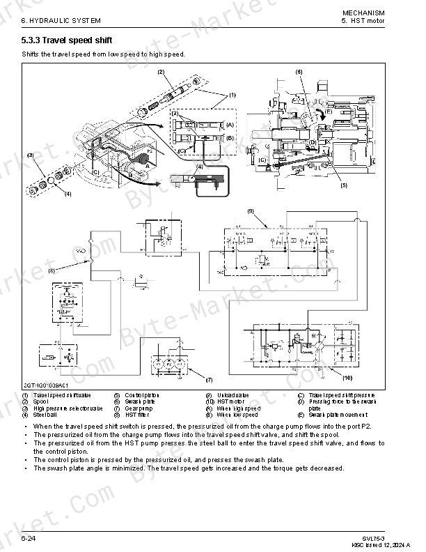
- 8.2.5 Travel motor "Travel speed shift" working principles(p. 195)
- 8.3 Travel system(p. 196)
- 8.3.1 Travel system "Forward" hydraulic description(p. 196)
- 8.3.2 Travel system "Reverse" hydraulic description(p. 197)
- 8.3.3 Travel system "Left swivel" hydraulic description(p. 198)
- 8.3.4 Travel system "right swivel" hydraulic description(p. 199)
- 8.3.5 Travel system "Pivot turn (forward left)" hydraulic description(p. 200)
- 8.3.6 Travel system "Charge circuit" hydraulic description(p. 201)
- 8.3.7 Anti-stall function of the travel system(p. 202)
- 9. Hydraulic cylinder(p. 203)
- 9.1 Hydraulic cylinder specifications(p. 203)
- 10. Unload valve (Travel speed shift, parking brake, working equipment)(p. 204)
- 10.1 Unload valve (Travel speed shift, parking brake, work equipment) specifications(p. 204)
- 10.2 Unload valve (Travel speed shift, parking brake, work equipment) functions and structures(p. 205)
- 10.2.1 Unload valve (Travel speed shift, parking brake, work equipment) working principles(p. 205)
- 11. Solenoid valve (Anti-stall, AUX)(p. 206)
- 11.1 Solenoid valve (Anti-stall, AUX) specifications(p. 206)
- 12. Solenoid valve (Hydraulic pressure quick hitch)(p. 207)
- 12.1 Solenoid valve (Hydraulic pressure quick hitch) specifications(p. 207)
- SERVICING(p. 209)
- 1. Troubleshooting hydraulic(p. 209)
- 1.1 Troubleshooting hydraulic for working equipment(p. 209)
- 1.2 Troubleshooting hydraulic for traveling(p. 211)
- 2. Measuring this machine(p. 213)
- 2.1 Hydraulic performance list(p. 213)
- 2.2 Hydraulic operating time(p. 213)
- 2.2.1 Measuring the operating time for lift arm cylinder(p. 213)
- 2.2.2 Measuring the operating time for bucket cylinder(p. 213)
- 2.2.3 Measuring the drift for working equipment(p. 214)
- 2.2.4 Measuring the operating time for travel motor(p. 214)
- 2.2.5 Measuring the block performance for travel motor(p. 214)
- 2.2.6 Measuring the travel straightness for the travel motor(p. 215)
- 3. HST pump(p. 215)
- 3.1 Measuring the HST pump(p. 215)
- 3.1.1 Measuring the flow rate for HST pump(p. 215)
- 3.1.2 Measuring travel relief pressure for HST pump(p. 216)
- 3.1.3 Adjusting the travel straightness for the HST pump(p. 216)
- 3.1.4 Adjusting swash plate neutral for HST pump(p. 217)
- 3.2 Removing/Installing the HST pump(p. 217)
- 3.2.1 Draining the hydraulic oil(p. 218)
- 3.2.2 Removing the cabin(p. 218)
- 3.2.3 Removing the step(p. 218)
- 3.2.4 Removing the LS pump(p. 220)
- 3.2.5 Removing the HST pump(p. 220)
- 3.3 Disassembling the HST pump(p. 221)
- 3.3.1 Disassembling the shaft assembly(p. 221)
- 3.3.2 Disassembling the cylinder block(p. 223)
- 3.3.3 Disassembling the relief valve(p. 224)
- 3.3.4 Disassembling the servo piston(p. 224)
- 3.4 Assembling the HST pump(p. 226)
- 3.4.1 Assembling the servo cylinder(p. 226)
- 3.4.2 Assembling the relief valve(p. 228)
- 3.4.3 Assembling the cylinder block (Engine side)(p. 229)
- 3.4.4 Assembling the shaft (Engine side)(p. 231)
- 3.4.5 Assembling the cylinder block (Pump side)(p. 233)
- 3.4.6 Assembling the the shaft (Pump side)(p. 233)
- 3.4.7 Assembling the adapter(p. 235)
- 3.5 HST pump components(p. 236)
- 3.6 Installing adapter layout for HST pump(p. 240)
- 3.7 Pump coupling parts drawing(p. 241)
- 4. Piston pump(p. 242)
- 4.1 Measuring the piston pump(p. 242)
- 4.1.1 Measuring the flow rate for piston pump(p. 242)
- 4.2 Bleeding air from the piston pump(p. 242)
- 4.3 Removing/Installing the piston pump(p. 243)
- 4.3.1 Removing the cabin(p. 243)
- 4.3.2 Removing the step(p. 243)
- 4.3.3 Installing the vacuum pump(p. 245)
- 4.3.4 Removing the piston pump(p. 245)
- 4.4 Disassembling the piston pump(p. 245)
- 4.4.1 Removing the gear pump(p. 246)
- 4.4.2 Removing the valve cover(p. 246)
- 4.4.3 Removing internal parts for piston pump(p. 247)
- 4.4.4 Disassembling the regulator for piston pump(p. 248)
- 4.5 Assembling the piston pump(p. 249)
- 4.5.1 Assembling the regulator for piston pump(p. 249)
- 4.5.2 Assembling internal parts for piston pump(p. 249)
- 4.5.3 Assembling valve cover for piston pump(p. 252)
- 4.5.4 Assembling the gear pump(p. 253)
- 4.6 Piston pump components(p. 254)
- 4.7 Installing adapter layout for piston pump(p. 256)
- 4.8 Servicing standards of piston pump(p. 257)
- 4.8.1 Measuring the piston clearance(p. 257)
- 4.8.2 Measuring the play for shoe crimping section(p. 257)
- 4.8.3 Measuring shoe thickness(p. 257)
- 4.8.4 Measuring the length for cylinder spring(p. 258)
- 4.8.5 Measuring the sinkage for spherical bushing(p. 258)
- 5. Control valve(p. 258)
- 5.1 Measuring the control valve(p. 258)
- 5.1.1 Measuring the unload LS valve(p. 258)
- 5.1.2 Measuring the LS relief valve(p. 259)
- 5.1.3 Measuring the overload relief valve(p. 259)
- 5.1.4 Adjusting the flow dividing valve(p. 260)
- 5.2 Removing/Installing the control valve(p. 260)
- 5.2.1 Removing the cabin(p. 261)
- 5.2.2 Installing the vacuum pump(p. 261)
- 5.2.3 Removing/Installing the control valve(p. 261)
- 5.3 Disassembling the control valve(p. 262)
- 5.3.1 Removing the section for control valve(p. 262)
- 5.3.2 Removing the flow divider section for the control valve(p. 264)
- 5.3.3 Removing the relief valve for the control valve(p. 265)
- 5.3.4 Removing the float solenoid valve for the control valve(p. 267)
- 5.4 Assembling the control valve(p. 268)
- 5.4.1 Assembling the section for control valve(p. 268)
- 5.4.2 Assembling the flow divider section for control valve(p. 270)
- 5.4.3 Assembling the relief valve for the control valve(p. 272)
- 5.4.4 Assembling the float solenoid valve for the control valve(p. 274)
- 5.5 Control valve components(p. 276)
- 5.6 Installing adapter layout for control valve(p. 279)
- 6. Travel motor(p. 281)
- 6.1 Removing/Installing the travel motor(p. 281)
- 6.1.1 Removing/Installing the rubber crawler(p. 281)
- 6.1.2 Installing the vacuum pump(p. 281)
- 6.1.3 Removing the travel motor(p. 281)
- 6.2 Disassembling the travel motor(p. 282)
- 6.2.1 Disassembling the gear case for travel motor(p. 282)
- 6.2.2 Disassembling the hydraulic motor for the travel motor(p. 285)
- 6.3 Assembling the travel motor(p. 288)
- 6.3.1 Assembling the gear case for travel motor(p. 288)
- 6.3.2 Assembly of travel motor(p. 293)
- 6.4 Travel motor components(p. 299)
- 6.5 Installing adapter layout for travel motor(p. 301)
- 7. Pilot valve(p. 301)
- 7.1 Measuring the piston pump(p. 301)
- 7.1.1 Measuring pressure for pilot valve(p. 301)
- 7.1.2 Measuring pressure for the pilot valve (Lift arm, bucket)(p. 302)
- 7.2 Disassembling the pilot valve(p. 302)
- 7.2.1 Removing the reducing valve(p. 303)
- 7.2.2 Disassembling the reducing valve(p. 304)
- 7.3 Assembling the pilot valve(p. 305)
- 7.3.1 Assembling the reducing valve(p. 305)
- 7.3.2 Assembling the pilot valve(p. 306)
- 7.4 Pilot valve components(p. 308)
- 8. Lift arm cylinder(p. 309)
- 8.1 Disassembling/Installing the lift arm cylinder(p. 309)
- 8.1.1 Removing the lift arm(p. 309)
- 8.1.2 Removing the battery(p. 309)
- 8.1.3 Removing the lift arm cylinder(p. 309)
- 8.2 Disassembling the lift arm cylinder(p. 310)
- 8.2.1 Disassembling the cylinder rod for lift arm cylinder(p. 310)
- 8.2.2 Disassembling the cylinder head for lift arm cylinder(p. 312)
- 8.3 Assembling the lift arm cylinder(p. 313)
- 8.3.1 Assembling the cylinder head for lift arm cylinder(p. 313)
- 8.3.2 Assembling the cylinder rod for lift arm cylinder(p. 314)
- 8.4 Servicing standards for hydraulic cylinder(p. 317)
- 8.4.1 Measuring the bend for cylinder rod(p. 317)
- 8.4.2 Measuring the wear for cylinder rod and cylinder head(p. 318)
- 8.4.3 Measuring the wear for the cylinder tube and piston wear ring(p. 318)
- 8.5 Lift arm cylinder components(p. 319)
- 9. Bucket cylinder(p. 320)
- 9.1 Removing/Installing the bucket cylinder(p. 320)
- 9.1.1 Removing the bucket cylinder(p. 320)
- 9.2 Bucket cylinder components(p. 322)
- 10. Hydraulic quick hitch cylinder(p. 323)
- 10.1 Removing/Installing the hydraulic quick hitch cylinder(p. 323)
- 10.1.1 Removing the quick hitch cylinder(p. 323)
- 10.2 Hydraulic quick hitch cylinder components(p. 323)
- 11. Unload valve(p. 324)
- 11.1 Removing/Installing the unload valve(p. 324)
- 11.1.1 Installing the vacuum pump(p. 324)
- 11.1.2 Cabin lock(p. 324)
- 11.1.3 Removing the unload valve(p. 324)
- 11.2 Installing adapter layout for unload valve(p. 326)
- 12. Solenoid valve (Anti-stall, AUX)(p. 327)
- 12.1 Disassembly/Assembly of solenoid valves (Anti-stall, AUX)(p. 327)
- 12.1.1 Installing the vacuum pump(p. 327)
- 12.1.2 Cabin lock(p. 327)
- 12.1.3 Removal of solenoid valve (Anti-stall, AUX)(p. 327)
- 12.2 Installing adapter layout for solenoid valve (Anti-stall, AUX)(p. 328)
- 13. Solenoid valve (Hydraulic pressure quick hitch)(p. 328)
- 13.1 Installing adapter layout for solenoid valve (Hydraulic quick hitch)(p. 328)
- 14. Hydraulic oil tank(p. 328)
- 14.1 Removing/Installing the hydraulic oil tank(p. 328)
- 14.1.1 Draining the hydraulic oil(p. 328)
- 14.1.2 Cabin lock(p. 329)
- 14.1.3 Removing the step(p. 329)
- 14.1.4 Removing the LS pump(p. 331)
- 14.1.5 Removing the hydraulic oil tank(p. 331)
- 14.2 Hydraulic oil tank components(p. 333)
- 14.3 Installing adapter layout for hydraulic oil tank(p. 335)
- 15. Hydraulic hoses(p. 336)
- 15.1 Total length for hydraulic hoses(p. 336)
- 15.2 Hydraulic hose fittings(p. 336)
- 15.3 Hose route(p. 337)
- 15.3.1 Piston pump(p. 337)
- 15.3.2 HST pump, HST filter(p. 339)
- 15.3.3 Control valve(p. 341)
- 15.3.4 Bucket cylinder(p. 344)
- 15.3.5 Unload valve(p. 345)
- 15.3.6 AUX solenoid valve(p. 347)
- 15.3.7 Relay, Pilot valve(p. 349)
- 15.3.8 Quick hitch model(p. 351)
- 16. Special jigs and tools(p. 353)
- 16.1 Piston ring correction jig(p. 353)
- 16.2 Shaft seal press-fit jig(p. 354)
- 16.3 Needle bearing insertion jig(p. 355)
- 16.4 U-joint tightening jig(p. 356)
- 16.5 Ring nut fastening jig(p. 357)
- 16.6 Angular bearing press-fit jig (upper)(p. 358)
- 16.7 Angular bearing press-fit jig (lower)(p. 359)
- 16.8 Roller bearing press-fit jig(p. 360)
- 16.9 Oil seal press-fit jig(p. 361)
- 16.10 Floating seal insertion jig(p. 362)
- 16.11 Ring gear disassembly jig(p. 364)
- 16.12 Inner race extraction jig(p. 365)
- 16.13 Piston ring correction jig(p. 366)
- 16.14 Seal ring insertion inner jig(p. 367)
- 16.15 Seal ring insertion jig(p. 368)
- 16.16 U ring insertion inner jig(p. 369)
- 16.17 U-ring insertion jig(p. 370)
- 16.18 Wiper ring press-fit jig(p. 371)
- 16.19 Bushing punching jig(p. 372)
- 16.20 Bushing press-fit jig(p. 373)
- 16.21 Handle(p. 374)
- 16.22 Bearing press-in jig(p. 374)
- 16.23 Piston pump dimension measuring jig(p. 375)
- 6. ELECTRICAL(p. 378)
- MECHANISM(p. 379)
- 1. Electrical circuit(p. 379)
- 1.1 Electrical circuit diagram notation(p. 379)
- 1.2 Electrical circuit diagram unit symbols(p. 379)
- 1.3 Electrical wiring color coding(p. 380)
- 1.4 Electrical wiring clamps(p. 380)
- 1.5 Bus notation(p. 381)
- 1.6 Battery terminal and composite terminal notation(p. 381)
- 2. Connector(p. 381)
- 2.1 Handling of connectors(p. 381)
- 2.2 Connector diagram notation(p. 381)
- 3. Electrical device(p. 383)
- 3.1 Layout of electrical device(p. 383)
- 4. Meter panel(p. 386)
- 4.1 Meter panel function(p. 386)
- 4.2 Lamps(p. 387)
- 4.3 Buzzer(p. 387)
- 4.4 Meter panel display list(p. 388)
- 4.5 Normal mode(p. 388)
- 4.5.1 Normal mode display(p. 388)
- 4.6 User settings mode(p. 388)
- 4.6.1 AUX flow rate setting in user setting mode(p. 388)
- 4.7 Service mode(p. 390)
- 4.7.1 Service mode settings list(p. 390)
- SERVICING(p. 391)
- 1. Troubleshooting electrical issues(p. 391)
- 1.1 Troubleshooting electrical(p. 391)
- 2. Troubleshooting errors(p. 391)
- 2.1 Error warning list(p. 391)
- 2.2 Engine error warning list(p. 393)
- 2.3 E:001 CAN communication error(p. 395)
- 2.3.1 Checking on the meter panel for E:001 CAN communication error(p. 395)
- 2.3.2 Checking on the meter panel for E:001 CAN communication error(p. 395)
- 2.3.3 Checking with circuit tester for E:001 CAN communication error(p. 396)
- 2.4 E:005 High hydraulic oil temperature(p. 396)
- 2.4.1 Checking on the meter panel for E:005 high hydraulic oil temperature(p. 396)
- 2.4.2 Checking devices for E:005 high hydraulic oil temperature(p. 396)
- 2.5 E:008 Fuel sensor error(p. 397)
- 2.5.1 Checking on the meter panel for E:008 fuel sensor error(p. 397)
- 2.5.2 Checking devices for E:008 fuel sensor error(p. 397)
- 2.5.3 Checking circuit tester for E:008 fuel sensor error(p. 398)
- 2.6 E:009 Accelerator dial sensor (Break or short)(p. 399)
- 2.6.1 Checking on the meter panel for E:009 accelerator sensor error(p. 399)
- 2.6.2 Checking devices for E:009 accelerator sensor error(p. 400)
- 2.6.3 Checking with circuit tester for E:009 Accelerator sensor error(p. 400)
- 2.7 E:010 Travel speed shift solenoid error(p. 401)
- 2.7.1 Checking on the meter panel for E:010 travel speed shift solenoid error(p. 401)
- 2.7.2 Checking devices for E:010 travel speed shift solenoid error(p. 402)
- 2.7.3 Checking with circuit tester for E:010 travel speed shift solenoid error(p. 402)
- 2.8 E:011 Parking brake solenoid error(p. 404)
- 2.8.1 Checking on the meter panel for E:011 parking brake solenoid error(p. 404)
- 2.8.2 Checking devices for E:011 parking brake solenoid error(p. 404)
- 2.8.3 Checking with circuit tester for E:011 parking brake solenoid error(p. 405)
- 2.9 E:012 Float solenoid error(p. 406)
- 2.9.1 Checking on the meter panel for E:012 float solenoid error(p. 406)
- 2.9.2 Checking devices for E:012 float solenoid error(p. 407)
- 2.9.3 Checking with circuit tester for E:012 float solenoid error(p. 407)
- 2.10 E:013 Hydraulic lock release solenoid error(p. 409)
- 2.10.1 Checking on the meter panel for E:013 hydraulic lock release solenoid error(p. 409)
- 2.10.2 Checking devices for E:013 hydraulic lock release solenoid error(p. 409)
- 2.10.3 Checking with circuit tester for E:013 hydraulic lock release solenoid error(p. 410)
- 2.11 E:014 Low hydraulic oil temperature error(p. 412)
- 2.11.1 Checking on the meter panel for E:014 low hydraulic oil temperature(p. 412)
- 2.11.2 Checking devices for E:014 low hydraulic oil temperature error(p. 412)
- 2.11.3 Checking with circuit tester for E:014 low hydraulic oil temperature error(p. 413)
- 2.12 E:015 Hydraulic hitch solenoid error(p. 414)
- 2.12.1 Checking on the meter panel for E:015 hydraulic hitch solenoid error(p. 414)
- 2.12.2 Checking devices for E:015 hydraulic hitch solenoid error(p. 414)
- 2.12.3 Checking with circuit tester for E:015 hydraulic hitch solenoid error(p. 415)
- 2.13 E:016 AUX knob-switch error(p. 417)
- 2.13.1 Checking on the meter panel for E:016 AUX knob-switch error(p. 417)
- 2.13.2 Checking devices for E:016 AUX knob-switch error(p. 417)
- 2.13.3 Checking with the circuit tester for E:016 AUX knob-switch error(p. 417)
- 2.14 E:018 AUX right solenoid error(p. 418)
- 2.14.1 Checking on the meter panel for E:018 AUX right solenoid error(p. 418)
- 2.14.2 Checking devices for E:018 AUX right solenoid error(p. 419)
- 2.14.3 Checking with circuit tester for E:018 AUX right solenoid error(p. 419)
- 2.15 E:019 AUX left solenoid error(p. 420)
- 2.15.1 Checking on the meter panel for E:019 AUX left solenoid error(p. 420)
- 2.15.2 Checking devices for E:019 AUX left solenoid error(p. 421)
- 2.15.3 Checking with circuit tester for E:019 AUX left solenoid error(p. 421)
- 2.16 E:020 Anti-stall solenoid error(p. 422)
- 2.16.1 Checking on the meter panel for E:020 Anti-stall solenoid error(p. 422)
- 2.16.2 Checking devices for E:020 Anti-stall solenoid error(p. 423)
- 2.16.3 Checking with circuit tester for E:020 Anti-stall solenoid error(p. 423)
- 2.17 E:021 5 V error(p. 424)
- 2.17.1 Checking on the meter panel for E:021 5 V error(p. 424)
- 2.17.2 Checking devices for E:021 5 V error(p. 424)
- 2.17.3 Checking external 5 V short with a circuit tester(p. 426)
- 2.18 E:023 Overvoltage(p. 429)
- 2.18.1 Checking on the meter panel for E:023 overvoltage(p. 429)
- 2.18.2 Checking devices for E:023 overvoltage(p. 429)
- 2.18.3 Checking with circuit tester for E:023 overvoltage(p. 429)
- 2.19 E:024 Hydraulic oil temperature sensor error(p. 430)
- 2.19.1 Checking on the meter panel for E:024 hydraulic oil temperature sensor error(p. 430)
- 2.19.2 Checking devices for E:024 hydraulic oil temperature sensor error(p. 430)
- 2.19.3 Checking with circuit tester for E:024 hydraulic oil temperature sensor error(p. 430)
- 2.20 E:026 CRS CAN communication error(p. 432)
- 2.20.1 Checking on the meter panel for E:026 CRS CAN communication error(p. 432)
- 2.20.2 Checking devices for E:026 CRS CAN communication error(p. 432)
- 2.20.3 Checking with circuit tester for E:026 CRS CAN communication error(p. 434)
- 2.21 E:027 ACU CAN communication error(p. 434)
- 2.21.1 Check on the meter panel for E:027 ACU CAN communication error(p. 434)
- 2.21.2 Checking devices for E:027 ACU CAN communication error(p. 435)
- 2.21.3 Check with circuit tester for E:027 ACU CAN communication error(p. 437)
- 2.22 E:028 Foot accelerator sensor error(p. 437)
- 2.22.1 Checking on the meter panel for E:028 foot accelerator sensor error(p. 437)
- 2.22.2 Checking devices for E:028 foot accelerator sensor error(p. 438)
- 2.22.3 Checking with circuit tester for E:028 foot accelerator sensor error(p. 438)
- 2.23 E:9116 Engine overheating(p. 440)
- 2.23.1 Checking on the meter panel for E:9116 Engine overheating(p. 440)
- 2.23.2 Checking devices for E:9116 engine overheating(p. 440)
- 2.24 E:9118 Engine oil pressure error(p. 440)
- 2.24.1 Checking on the meter panel for E:9118 engine oil pressure error(p. 440)
- 2.24.2 Checking devices for E:9118 engine oil pressure error(p. 441)
- 2.24.3 Checking with circuit tester for E:9118 engine oil pressure error(p. 442)
- 2.25 E:9119 Battery charging error(p. 443)
- 2.25.1 Checking on the meter panel for E:9119 battery charging error(p. 443)
- 2.25.2 Checking devices for E:9119 battery charging error(p. 443)
- 2.25.3 Checking with circuit tester for E:9119 battery charging error(p. 443)
- 2.26 E:9120 Water separator error(p. 444)
- 2.26.1 Checking on the meter panel for E:9120 water separator error(p. 444)
- 2.26.2 Checking devices for E:9120 water separator error(p. 444)
- 2.26.3 Checking with circuit tester for E:9120 water separator error(p. 445)
- 3. Meter panel settings(p. 445)
- 3.1 Meter panel switches operation(p. 445)
- 3.2 AUX flow rate setting(p. 445)
- 3.3 Service mode operations(p. 446)
- 3.4 No-01 Tester mode(p. 446)
- 3.5 No-02 AUX knob setting(p. 450)
- 3.6 No-03 AUX start-up point setting(p. 450)
- 3.7 No-04 AUX current fine setting(p. 451)
- 3.8 No-05 HST start-up point setting(p. 452)
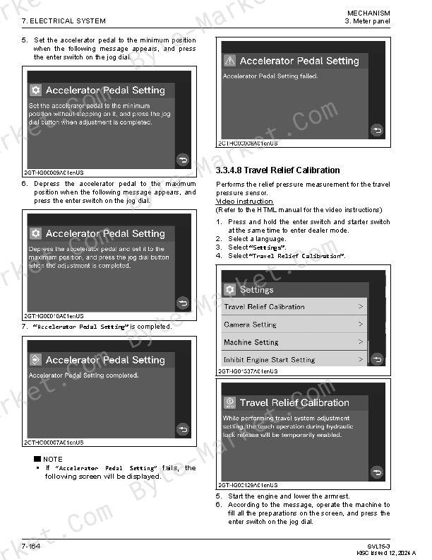
- 3.9 No-07 Accelerator pedal/dial setting(p. 453)
- 3.10 No-09 Read error history(p. 453)
- 3.11 No-10 Clear error history(p. 453)
- 3.12 No-11 Read all error history(p. 454)
- 3.13 No-12 AUX flow rate adjustment(p. 454)
- 7. AIR CONDITIONING(p. 456)
- MECHANISM(p. 457)
- 1. Air conditioning system(p. 457)
- 1.1 Air conditioning equipments layout(p. 457)
- 1.2 Air conditioning system general description(p. 459)
- 2. Compressor(p. 460)
- 2.1 Compressor specifications(p. 460)
- 2.2 Compressor functions and structures(p. 461)
- 2.3 Magnetic clutch functions and structures(p. 461)
- 2.4 Safety valve functions and structures(p. 462)
- 2.5 Temperature sensor functions and structures(p. 462)
- 2.6 Compressor oil functions and structures(p. 462)
- 3. Air conditioner unit(p. 463)
- 3.1 Air conditioning specifications(p. 463)
- 3.2 Evaporator functions and structures(p. 464)
- 3.3 Heater core functions and structures(p. 464)
- 3.4 Blower motor functions and structures(p. 464)
- 3.5 Blower resistor functions and structures(p. 465)
- 3.6 Expansion valve functions and structures(p. 465)
- 3.7 Fin thermistor functions and structures(p. 466)
- 3.8 Hot water valve functions and structures(p. 466)
- 4. Capacitor(p. 467)
- 4.1 Condenser specifications(p. 467)
- 4.2 Condenser functions and structures(p. 467)
- 5. Receiver(p. 467)
- 5.1 Receiver specifications(p. 467)
- 5.2 Receiver functions and structures(p. 468)
- 6. Pressure switch(p. 468)
- 6.1 Pressure switch specifications(p. 468)
- 6.2 Pressure switch functions and structures(p. 469)
- SERVICING(p. 471)
- 1. Troubleshooting(p. 471)
- 1.1 Troubleshooting the air conditioning system(p. 471)
- 1.2 Troubleshooting the compressor(p. 473)
- 2. Fuse(p. 473)
- 2.1 Checking the fuses(p. 473)
- 3. Relay(p. 474)
- 3.1 Checking the relays(p. 474)
- 4. Air conditioning control panel(p. 475)
- 4.1 Checking the air conditioning control panel(p. 475)
- 5. Air conditioning system(p. 476)
- 5.1 Special tools for air conditioning system(p. 477)
- 5.2 Measuring and checking the air conditioning system(p. 480)
- 5.2.1 Connecting the manifold gauge set(p. 480)
- 5.2.2 Measuring the refrigeration cycle(p. 481)
- 5.2.3 Normal refrigeration cycle(p. 481)
- 5.2.4 Undercharged(p. 481)
- 5.2.5 Excess refrigerant or insufficient condenser cooling(p. 481)
- 5.2.6 Air is mixed in the refrigerant cycle(p. 482)
- 5.2.7 Moisture mixed into the refrigeration cycle(p. 482)
- 5.2.8 Refrigerant fails to circulate(p. 483)
- 5.2.9 Expansion valve too far open(p. 483)
- 5.2.10 Compressor failure(p. 483)
- 5.2.11 Checking with the sight glass(p. 484)
- 5.3 Collecting refrigerant(p. 484)
- 5.4 Evacuating the refrigeration cycle(p. 485)
- 5.5 Charging refrigerant(p. 485)
- 5.5.1 Connecting to the refrigerant recharging equipment and service canister(p. 485)
- 6. Compressor(p. 487)
- 6.1 Measuring and checking the compressor(p. 487)
- 6.2 Removing/Installing the compressor(p. 487)
- 6.3 Oil amount in the compressor(p. 489)
- 7. Air conditioner unit(p. 489)
- 7.1 Measuring and checking the air conditioning unit(p. 489)
- 7.1.1 Measuring and checking the blower motor(p. 489)
- 7.1.2 Measuring and checking the blower resistor(p. 490)
- 7.2 Removing/Installing the air conditioning unit(p. 490)
- 7.3 Air conditioning unit parts drawing(p. 493)
- 8. Condenser and receiver(p. 493)
- 8.1 Measuring and checking the condenser(p. 493)
- 8.1.1 Measuring and checking the condenser fan motor(p. 493)
- 8.2 Removing/Installing the condenser and the receiver(p. 493)
- 9. Air conditioning hose(p. 495)
- 9.1 Removing/Installing the air conditioning hose(p. 495)
- 10. Heater hose(p. 496)
- 10.1 Removing/Installing the heater hose(p. 496)
- APPENDICES(p. 497)
- INDEX(p. 518)
Delivery (Instant Download)
This manual is supplied as a digital PDF file and is available for instant download after purchase. No physical media is shipped.
References
Kubota SVL95-2S Workshop Manual.
Document number: RY911-23872.
PDF edition.


No questions found.