
Kubota U-10, U-20, U-35, and U-45 Workshop Manual
Document number 97899-60501 · English PDF edition · 1052 pages
About this manual
Kubota published this Workshop Manual for the U-10, U-20, U-35, and U-45 excavator models. It brings the documented service and technical-reference material for those named excavators into a single publication.
Use the Manual Contents below to check that the exact repair, inspection, or maintenance procedure you need is included in this publication.
Manual details
- Manufacturer
- Kubota
- Manual type
- Workshop Manual
- Models
- U-10, U-20, U-35, and U-45
- Document number
- 97899-60501
- Language
- English
- Page count
- 1052
Manual contents
Use these source headings to locate the required system or procedure in the PDF.
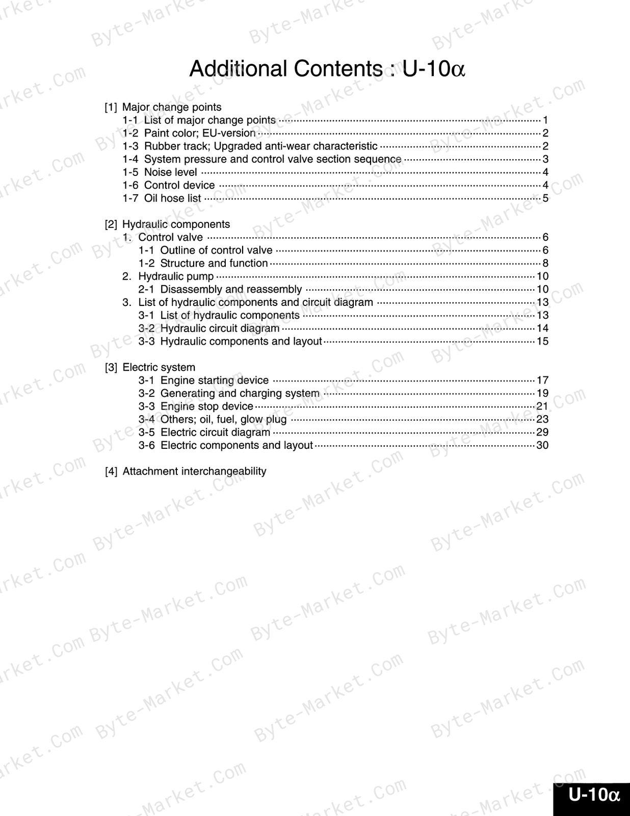
- Additional Contents: U-10α
- Major Change Points
- 1-1 List of Major Change Points — p. 1
- 1-2 Paint Color; EU-Version — p. 2
- 1-3 Rubber Track; Upgraded Anti-Wear Characteristic — p. 2
- 1-4 System Pressure and Control Valve Section Sequence — p. 3
- 1-5 Noise Level — p. 4
- 1-6 Control Device — p. 4
- 1-7 Oil Hose List — p. 5
- Hydraulic Components
- Control Valve — p. 6
- 1-1 Outline of Control Valve — p. 6
- 1-2 Structure and Function — p. 8
- Hydraulic Pump — p. 10
- 2-1 Disassembly and Reassembly — p. 10
- List of Hydraulic Components and Circuit Diagram — p. 13
- 3-1 List of Hydraulic Components — p. 13
- 3-2 Hydraulic Circuit Diagram — p. 14
- 3-3 Hydraulic Components and Layout — p. 15
- Control Valve — p. 6
- Electric System
- 3-1 Engine Starting Device — p. 17
- 3-2 Generating and Charging System — p. 19
- 3-3 Engine Stop Device — p. 21
- 3-4 Others; Oil, Fuel, Glow Plug — p. 23
- 3-5 Electric Circuit Diagram — p. 29
- 3-6 Electric Components and Layout — p. 30
- Attachment Interchangeability
- Major Change Points
- General — p. 34
- Mechanism — p. 36
- Section 1 — p. 172
- General Layout: U-35 — 1-M1
- Arm: U-20, U-35 — 1-M2
- Telescopic Frame / Telescopic Dozer Blade: U-10, 20 — 1-M3
- Function of Telescopic Frame — 1-M4
- Service Specification of Rubber Track — 1-M6
- Section 2 — p. 332
- Feature — 2-M1
- Low-Noise — 2-M1
- Environment Friendly Exhaust Gas Control — 2-M1
- Specification — 2-M1
- Cooling System — 2-M2
- Radiator — 2-M3
- Fuel System — 2-M5
- Fuel Line — 2-M5
- Fuel Filter — 2-M5
- Water Separator — 2-M6
- Electro Magnetic Fuel Feed Pump — 2-M7
- Injection Pump — 2-M7
- Injection Nozzle — 2-M9
- Governor — 2-M10
- Engine Performance Curve — 2-M12
- Feature — 2-M1
- Section 3 — p. 432
- Hydraulic Components Specifications — 3-M1
- Hydraulic Components Layout, Flow & Hydraulic Circuit Diagram — 3-M3
- U-10 — 3-M3
- U-20 — 3-M8
- U-35 — 3-M12
- Hydraulic System Specifications — 3-M18
- Specifications — 3-M18
- Breaker Applicational Compatibility — 3-M19
- Hydraulic Components Function & Structure — 3-M20
- Main Pump — 3-M20
- Control Valve — 3-M27
- Pilot Valve (U-20, U-35, U-45) — 3-M44
- Change Valve (U-20, U-35, U-45) — 3-M50
- Swivel Motor — 3-M51
- Wheel Motor (Travel Motor) — 3-M63
- Section 4 — p. 985
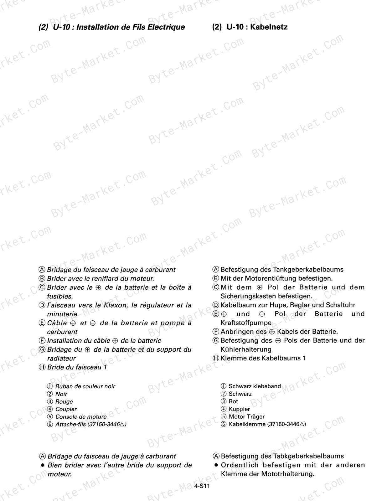
- Electrical Circuit Diagram — 4-M1
- U-10 — 4-M1
- U-20 — 4-M2
- U-35 — 4-M3
- U-45 — 4-M4
- Electrical Components Layout — 4-M5
- U-10 Layout — 4-M5
- U-20 Layout — 4-M6
- U-35 Layout — 4-M7
- Electrical Current Flow Chart — 4-M8
- Glow — 4-M8
- Switch Turn On: AC Stage — 4-M8
- Engin Start: 50 Position — 4-M9
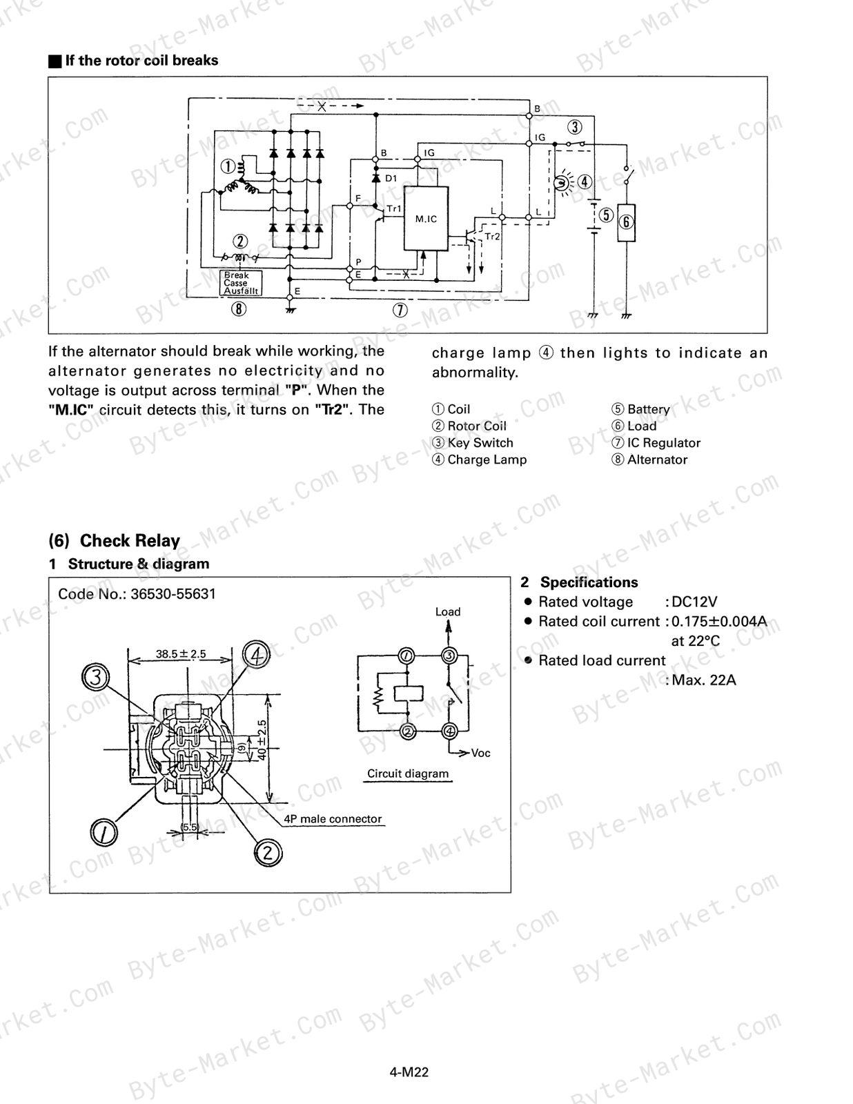
- Charging Circuit — 4-M9
- Safety Lever Lock Circuit — 4-M10
- Oil, Coolant & Fuel Warning Circuit — 4-M10
- Engine Stop Circuit — 4-M11
- Electrical Equipment — 4-M12
- Structure & Functions — 4-M16
- Electrical Circuit Diagram — 4-M1
- Section 1 — p. 172
Capabilities
The source outline indexes mechanism explanations. Use these source-backed headings to locate the applicable task or system in the source PDF, then confirm model-specific notes, specifications, illustrations, and operating conditions at the relevant page before carrying out service work.
Keep the source's safety sequence, prerequisite steps, labels, units, configuration notes, and footnotes with the selected task; do not apply an isolated value outside the conditions stated in the manual.
Delivery
This manual is supplied as a digital PDF file and is available for instant download after purchase. No physical media is shipped.
References
Kubota Workshop Manual for Excavator, document code 97899-60501, PDF edition.


No questions found.