
Kubota Workshop Manual
Kubota U48-4 and U55-4 Workshop Manual
Document number RY921-20530 · English PDF edition · 799 pages
About this manual
Kubota published this Workshop Manual for the U48-4 and U55-4 excavator models. It brings the documented service and technical-reference material for those named excavators into a single publication.
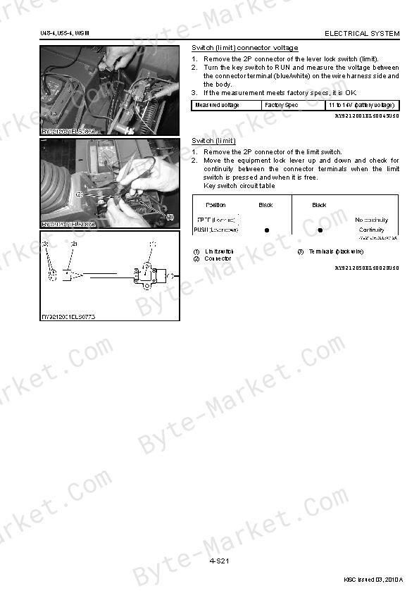
The manual is especially useful for work that crosses electrical and hydraulic systems: it includes electrical troubleshooting, alongside hydraulic diagrams, pressure-test evidence, and valve-adjustment information.
Use the Manual Contents below to check that the exact repair, inspection, or maintenance procedure you need is included in this publication.
Manual details
- Manufacturer
- Kubota
- Manual type
- Workshop Manual
- Models
- U48-4 and U55-4
- Document number
- RY921-20530
- Language
- English
- Page count
- 799
Product highlights
Electrical systems
The manual includes wiring diagrams, electrical troubleshooting, and pinouts.
Hydraulic systems
The manual includes hydraulic circuit diagrams, hydraulic pressure-test material, and hydraulic valve-adjustment material.
Specifications and settings
The manual includes reference information for torque specifications, wear limits, and dimensions.
Special tools
A special-tools section is included.
Maintenance
The manual includes a maintenance schedule and a lubrication chart.
Manual contents
Use these source headings to locate the task or system you need in the PDF.
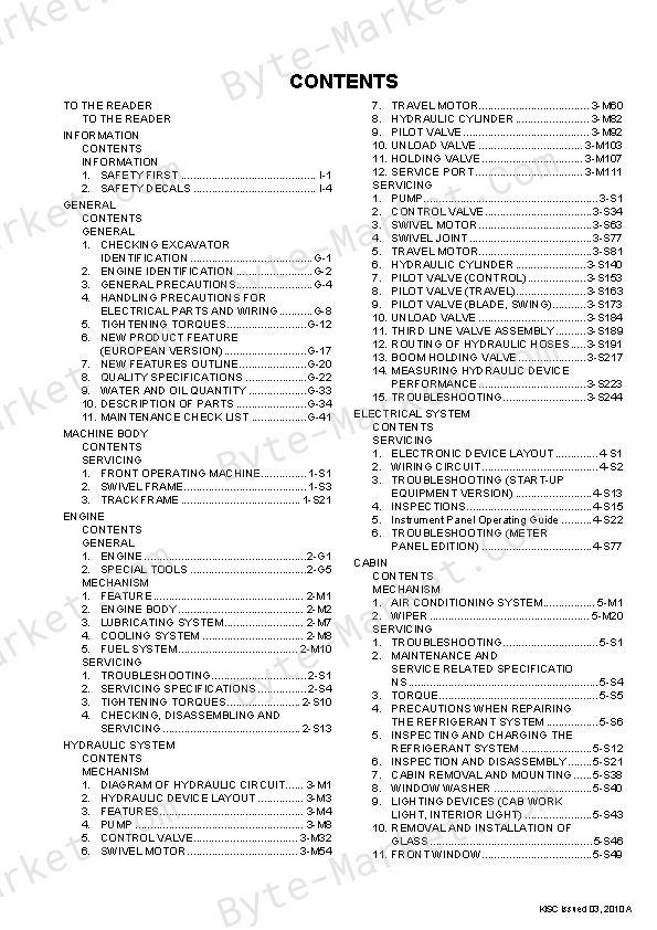
- CONTENTS — p. 1
- TO THE READER — p. 2
- I INFORMATION — p. 4
- INFORMATION — p. 5
- 1. SAFETY FIRST — p. 6
- 2. SAFETY DECALS — p. 9
- INFORMATION — p. 5
- G GENERAL — p. 14
- GENERAL — p. 15
- 1. CHECKING EXCAVATOR IDENTIFICATION — p. 16
- 2. ENGINE IDENTIFICATION — p. 17
- [1] MODEL NAME AND SERIAL NUMBER — p. 17
- [2] E3B ENGINE — p. 18
- [3] CYLINDER NUMBER — p. 18
- 3. GENERAL PRECAUTIONS — p. 19
- 4. HANDLING PRECAUTIONS FOR ELECTRICAL PARTS AND WIRING — p. 23
- [1] WIRING — p. 23
- [2] FUSES — p. 25
- [3] CONNECTOR — p. 25
- [4] WASHING THE EXCAVATOR WITH A HIGH-PRESSURE WASHER — p. 26
- 5. TIGHTENING TORQUES — p. 27
- [1] GENERAL USE SCREWS, BOLTS AND NUTS — p. 27
- [2] STUD BOLTS — p. 27
- [3] TORQUE FOR HYDRAULIC HOSE FITTINGS — p. 28
- (1) Torque for Hydraulic Hose Fittings — p. 28
- (2) Torques of Lock-Nuts for Elbows with Male Seats and Adaptors with O-rings (Straight Threads) — p. 29
- (3) Torque for Tapering Adaptors — p. 29
- [4] HOSE CLAMP SCREW TORQUE — p. 30
- 6. NEW PRODUCT FEATURE (EUROPEAN VERSION) — p. 32
- 7. NEW FEATURES OUTLINE — p. 35
- 8. QUALITY SPECIFICATIONS — p. 37
- 9. WATER AND OIL QUANTITY — p. 48
- 10. DESCRIPTION OF PARTS — p. 49
- [1] BUCKET — p. 49
- (1) Bucket dimensions — p. 49
- (2) Bucket installation relevant dimensions — p. 50
- [2] RUBBER CRAWLER — p. 51
- [3] STEEL CRAWLER — p. 51
- [4] TRUCK ROLLER, IDLER, SPROCKET — p. 52
- [5] CYLINDER — p. 53
- [6] PARTS WEIGHT — p. 54
- [1] BUCKET — p. 49
- 11. MAINTENANCE CHECK LIST — p. 56
- GENERAL — p. 15
- 1 MACHINE BODY — p. 58
- SERVICING — p. 59
- 1. FRONT OPERATING MACHINE — p. 60
- [1] BLADE — p. 60
- (1) Blade dimension — p. 60
- [2] FRONT PIN — p. 61
- [1] BLADE — p. 60
- 2. SWIVEL FRAME — p. 62
- [1] WEIGHT DIASSEMBLY / ASSEMBLY — p. 62
- [2] FUEL TANK — p. 64
- [3] HYDRAULIC OIL TANK — p. 67
- (1) Hydraulic oil tank components — p. 67
- (2) Hydraulic oil return filter replacement procedure — p. 68
- (3) Filter (suction) replacement procedure — p. 69
- (4) Filter (breather) replacement procedure — p. 70
- (5) Assembly of anti vibration support for the hydraulic oil tank — p. 71
- [4] ENGINE — p. 72
- (1) Engine mount — p. 72
- (2) Muffler — p. 73
- (3) Arch, Air cleaner — p. 74
- (4) Radiator — p. 75
- (5) Oil cooler — p. 76
- (6) Accelerator cable — p. 77
- [5] ASSEMBLING OF OPERATING LEVERS — p. 78
- (1) Travel lever — p. 78
- (2) Blade lever — p. 79
- 3. TRACK FRAME — p. 80
- [1] ASSEMBLING OF SWIVEL BEARING — p. 80
- [2] TRACK — p. 82
- (1) Assembly / disassembly of rubber track — p. 82
- (2) Assembly / disassembly of iron tracks — p. 83
- [3] FRONT IDLER — p. 86
- (1) Assembly / disassembly of front idler — p. 86
- (2) Front idler structural components — p. 86
- [4] SPRING ASSY — p. 87
- (1) Assembly / disassembly of spring assy — p. 87
- [5] CYLINDER ASSEMBLY — p. 88
- (1) Assembly / disassembly of cylinder assy — p. 88
- (2) Cylinder assembly structural components — p. 88
- [6] TRACK ROLLER — p. 90
- (1) Assembly / disassembly of track roller — p. 90
- (2) Track roller structural components — p. 91
- [7] CARRIER ROLLER — p. 92
- (1) Assembly / disassembly of carrier roller — p. 92
- (2) Carrier roller structural components — p. 93
- 1. FRONT OPERATING MACHINE — p. 60
- SERVICING — p. 59
- 2 ENGINE — p. 94
- GENERAL — p. 95
- 1. ENGINE — p. 96
- [1] ENGINE SPECIFICATIONS — p. 96
- [2] PERFORMANCE CURVE — p. 98
- [3] DIMENSIONS — p. 99
- 2. SPECIAL TOOLS — p. 100
- 1. ENGINE — p. 96
- MECHANISM — p. 115
- 1. FEATURE — p. 116
- 2. ENGINE BODY — p. 117
- [1] CYLINDER BLOCK — p. 117
- [2] COOLING JACKET — p. 117
- [3] HALF-FLOATING HEAD COVER — p. 118
- [4] CYLINDER HEAD — p. 118
- [5] 4 SCREWS PER EACH CYLINDER ASSEMBLING STRUCTURE — p. 119
- [6] CENTER DIRECT INJECTION SYSTEM (E-CDIS) — p. 120
- [7] GEAR TRAIN CONFIGURATION — p. 121
- [8] PISTON — p. 121
- 3. LUBRICATING SYSTEM — p. 122
- [1] OIL COOLER — p. 122
- 4. COOLING SYSTEM — p. 123
- [1] THERMOSTAT — p. 123
- [2] BOTTOM BYPASS SYSTEM — p. 124
- 5. FUEL SYSTEM — p. 125
- [1] GOVERNOR — p. 125
- [2] 2 STAGE DI NOZZLE — p. 127
- [3] INJECTION PUMP WITH F.S.P. — p. 128
- [4] CPV EQUIPPED DELIVERY VALVE — p. 129
- SERVICING — p. 130
- 1. TROUBLESHOOTING — p. 131
- 2. SERVICING SPECIFICATIONS — p. 134
- 3. TIGHTENING TORQUES — p. 140
- [1] TIGHTENING TORQUES FOR GENERAL USE SCREWS, BOLTS AND NUTS — p. 140
- [2] TIGHTENING TORQUES FOR SPECIAL USE SCREWS, BOLTS AND NUTS — p. 141
- 4. CHECKING, DISASSEMBLING AND SERVICING — p. 143
- [1] CHECKING AND ADJUSTING — p. 143
- (1) Engine Body — p. 143
- (2) Lubricating System — p. 145
- (3) Cooling System — p. 145
- (4) Fuel System — p. 148
- (5) Electrical System — p. 151
- [2] DISASSEMBLING AND ASSEMBLING — p. 155
- (1) Draining Oil and Coolant — p. 155
- (2) External Components — p. 155
- (3) Cylinder Head and Valves — p. 156
- (4) Thermostat — p. 160
- (5) Injection Pump Unit — p. 161
- (6) Water Pump and Oil Cooler — p. 171
- (7) Front Cover — p. 171
- (8) Flywheel and Timing Gears — p. 172
- (9) Piston and Connecting Rod — p. 175
- (10) Crankshaft and Crankcase — p. 178
- (11) Starter — p. 180
- (12) Alternator — p. 180
- [3] SERVICING — p. 183
- (1) Cylinder Head and Valves — p. 183
- (2) Timing Gears — p. 189
- (3) Piston and Connecting Rod — p. 191
- (4) Crankshaft — p. 195
- (5) Cylinder — p. 200
- (6) Oil Pump — p. 200
- (7) Relief Valve — p. 201
- (8) Starter — p. 202
- (9) Alternator — p. 204
- [1] CHECKING AND ADJUSTING — p. 143
- GENERAL — p. 95
- 3 HYDRAULIC SYSTEM — p. 205
- MECHANISM — p. 206
- 1. DIAGRAM OF HYDRAULIC CIRCUIT — p. 208
- 2. HYDRAULIC DEVICE LAYOUT — p. 210
- 3. FEATURES — p. 211
- [1] ADOPTION OF THE 1-PUMP LS SYSTEM [U48-4] — p. 211
- [2] ADOPTION OF THE 3-PUMP LS SYSTEM [U55-4] — p. 211
- [3] LOAD PRESSURE DETECTION SYSTEM — p. 212
- [4] ADOPTION OF AN AUTOMATIC SPEED REDUCTION FUNCTION ON THE TRAVEL MOTOR — p. 213
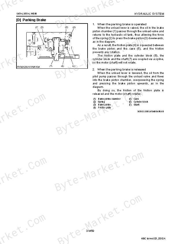
- [5] ADOPTION OF A PARKING BRAKE TO THE TRAVEL MOTOR — p. 213
- [6] ADOPTION OF AN OIL PRESSURE PILOT SYSTEM FOR ALL OPERATIONS — p. 213
- [7] CHARACTERISTICS OF LS PUMPS — p. 214
- (1) Variable displacement pump with LS control functions — p. 214
- (2) Variable displacement pump without LS control functions — p. 214
- (3) Gear Pump — p. 214
- 4. PUMP — p. 215
- [1] PUMP (48-4) — p. 215
- (1) Specifications — p. 215
- (2) Components — p. 218
- (3) Function and Structure — p. 220
- [2] PUMP (U55-4) — p. 226
- (1) Specifications — p. 226
- (2) Components — p. 230
- (3) Function and Structure — p. 232
- [1] PUMP (48-4) — p. 215
- 5. CONTROL VALVE — p. 239
- [1] CONTROL VALVE [U48-4] — p. 239
- (1) Specifications — p. 239
- (2) Diagram of Hydraulic Circuit — p. 241
- (3) Function & Structure — p. 242
- [2] CONTROL VALVE [U55-4] — p. 251
- (1) Specifications — p. 251
- (2) Diagram of Hydraulic Circuit — p. 253
- (3) Function and Structure — p. 253
- [1] CONTROL VALVE [U48-4] — p. 239
- 6. SWIVEL MOTOR — p. 261
- [1] SWIVEL MOTOR [U48-4, U55-4] — p. 261
- (1) Specifications — p. 261
- (2) Components — p. 262
- (3) Function and Structure — p. 264
- [1] SWIVEL MOTOR [U48-4, U55-4] — p. 261
- 7. TRAVEL MOTOR — p. 267
- [1] TRAVEL MOTOR [U48-4] — p. 267
- (1) Specifications — p. 267
- (2) Components — p. 268
- (3) Function & Structure — p. 270
- [2] TRAVEL MOTOR [U55-4] — p. 278
- (1) Specifications — p. 278
- (2) Components — p. 280
- (3) Function and Structure — p. 282
- [1] TRAVEL MOTOR [U48-4] — p. 267
- 8. HYDRAULIC CYLINDER — p. 289
- [1] BOOM CYLINDER [U48-4, U55-4] — p. 289
- (1) Specifications — p. 289
- (2) Components — p. 289
- (3) Function & Structure — p. 291
- [2] ARM CYLINDER [U48-4, U55-4] — p. 292
- (1) Specifications — p. 292
- (2) Components — p. 292
- (3) Function and Structure — p. 294
- [3] BUCKET CYLINDER [U48-4, U55-4] — p. 295
- (1) Specifications — p. 295
- (2) Components — p. 295
- [4] SWING CYLINDER [U48-4, U55-4] — p. 297
- (1) Specifications — p. 297
- (2) Components — p. 297
- [5] BLADE CYLINDER [U48-4, U55-4] — p. 298
- (1) Specifications — p. 298
- (2) Components — p. 298
- [1] BOOM CYLINDER [U48-4, U55-4] — p. 289
- 9. PILOT VALVE — p. 299
- [1] PILOT VALVE (BOOM, ARM, BUCKET, SWIVEL) [U48-4, U55-4] — p. 299
- (1) Specifications — p. 299
- (2) Components — p. 301
- (3) Function and Structure — p. 302
- [2] PILOT VALVE (TRAVEL) [U48-4, U55-4] — p. 303
- (1) Specifications — p. 303
- (2) Components — p. 304
- (3) Function and Structure — p. 305
- [3] PILOT VALVE (SWING, BLADE) [U48-4, U55-4] — p. 307
- (1) Specifications — p. 307
- (2) Components — p. 308
- (3) Function and Structure — p. 309
- [1] PILOT VALVE (BOOM, ARM, BUCKET, SWIVEL) [U48-4, U55-4] — p. 299
- 10. UNLOAD VALVE — p. 310
- [1] UNLOAD VALVE [U48-4, U55-4] — p. 310
- (1) Specifications — p. 310
- (2) Components — p. 311
- (3) Function and Structure — p. 312
- [1] UNLOAD VALVE [U48-4, U55-4] — p. 310
- 11. HOLDING VALVE — p. 314
- [1] BOOM HOLDING VALVE — p. 314
- (1) Specifications — p. 314
- (2) Components — p. 315
- (3) Function and Structure — p. 316
- [1] BOOM HOLDING VALVE — p. 314
- 12. SERVICE PORT — p. 318
- [1] SERVICE PORT — p. 318
- (1) Specifications — p. 318
- (2) Components — p. 320
- (3) Function and Structure — p. 322
- [1] SERVICE PORT — p. 318
- SERVICING — p. 328
- 1. PUMP — p. 330
- [1] PUMP DISASSEMBLY / ASSEMBLY — p. 330
- [2] PUMP DISASSEMBLY PROCEDURES [U48-4] — p. 336
- (1) Disassembly Procedures — p. 338
- (2) Assembly Procedures — p. 342
- [3] PUMP DISASSEMBLY PROCEDURES [U55-4] — p. 347
- (1) Disassembly Procedures — p. 349
- (2) Assembly Procedures — p. 355
- [4] SPECIAL TOOLS — p. 361
- [5] STANDARDS FOR REPLACING PUMP PARTS — p. 362
- 2. CONTROL VALVE — p. 363
- [1] CONTROL VALVE REMOVAL — p. 363
- [2] CONTROL VALVE DISASSEMBLY / ASSEMBLY PROCEDURES — p. 368
- (1) Control Valve [U48-4] — p. 369
- (2) Control Valve [U55-4] — p. 380
- 3. SWIVEL MOTOR — p. 392
- [1] REMOVAL AND INSTALLATION OF THE SWIVEL MOTOR — p. 392
- [2] SWIVEL MOTOR ASSEMBLY PROCEDURES — p. 395
- (1) Assembly Procedures — p. 397
- 4. SWIVEL JOINT — p. 406
- [1] SWIVEL JOINT REMOVAL & INSTALLATION — p. 406
- 5. TRAVEL MOTOR — p. 410
- [1] REMOVAL AND INSTALLATION OF THE TRAVEL MOTOR — p. 410
- [2] TRAVEL MOTOR DISASSEMBLY / ASSEMBLY PROCEDURES [U48-4] — p. 413
- (1) Disassembly Procedures — p. 415
- (2) Assembly Procedures — p. 425
- [3] TRAVEL MOTOR DISASSEMBLY / ASSEMBLY PROCEDURES [U55-4] — p. 440
- (1) Disassembly Procedures — p. 442
- (2) Assembly Procedures — p. 452
- [4] SPECIAL TOOLS — p. 466
- 6. HYDRAULIC CYLINDER — p. 469
- [1] HYDRAULIC CYLINDER DISASSEMBLY / ASSEMBLY PROCEDURES — p. 469
- (1) Cylinder Components — p. 469
- (2) Disassembly Procedures — p. 471
- (3) Assembly Procedures — p. 475
- [1] HYDRAULIC CYLINDER DISASSEMBLY / ASSEMBLY PROCEDURES — p. 469
- 7. PILOT VALVE (CONTROL) — p. 482
- [1] PILOT VALVE (CONTROL) ASSEMBLY — p. 482
- [2] PILOT VALVE (CONTROL) DISASSEMBLY / ASSEMBLY PROCEDURES — p. 484
- (1) Pilot valve components — p. 484
- (2) Disassembly — p. 484
- (3) Assembly — p. 488
- (4) U-joint Tightening Tool — p. 491
- 8. PILOT VALVE (TRAVEL) — p. 492
- [1] PILOT VALVE (TRAVEL) ASSEMBLY — p. 493
- [2] PILOT VALVE (TRAVEL) DISASSEMBLY / ASSEMBLY PROCEDURES — p. 494
- (1) Disassembly Procedures — p. 494
- (2) Assembly Procedures — p. 497
- 9. PILOT VALVE (BLADE, SWING) — p. 502
- [1] PILOT VALVE (BLADE, SWING) ASSEMBLY — p. 502
- [2] PILOT VALVE (BLADE, SWING) DISASSEMBLY / ASSEMBLY PROCEDURES — p. 504
- (1) Disassembly — p. 505
- (2) Assembly — p. 508
- 10. UNLOAD VALVE — p. 513
- [1] UNLOAD VALVE ASSEMBLY — p. 513
- [2] UNLOAD VALVE DISASSEMBLY / ASSEMBLY PROCEDURES — p. 514
- (1) Disassembly / Assembly Procedures — p. 515
- 11. THIRD LINE VALVE ASSEMBLY — p. 518
- [1] THIRD LINE VALVE ASSEMBLY COMPONENTS — p. 518
- [2] THIRD LINE HOSE ROUTE — p. 519
- 12. ROUTING OF HYDRAULIC HOSES — p. 520
- [1] TABLE OF HYDRAULIC HOSES — p. 520
- (1) Hydraulic Hoses — p. 520
- (2) Table of High-Pressure Hoses — p. 521
- (3) Delivery Hose Routing (U48-4) — p. 524
- (4) Delivery Hose Routing (U55-4) — p. 524
- (5) Delivery Hose Clamp Positions — p. 525
- (6) Suction Pipe — p. 526
- (7) Installation of Pipes (suction) — p. 527
- (8) Front Hose Routing (U48-4, U55-4) — p. 527
- (9) High-pressure Hydraulic Hose Routing (Travel, Swivel, Blade, Swing) (U48-4) — p. 528
- (10) High-pressure Hydraulic Hose Routing (Travel, Swivel, Blade, Swing) (U55-4) — p. 529
- (11) Swivel Hose Routing — p. 530
- (12) Travel Motor Hose Routing — p. 530
- (13) Hose Routing Inside the Track Frame (U48-4, U55-4) — p. 531
- [2] TABLE OF HYDRAULIC HOSES (LOW-PRESSURE HOSES) — p. 532
- (1) Table of Low-Pressure Hoses — p. 532
- (2) Table of Protective Tubing — p. 532
- (3) Drain Hose Routing (U48-4) — p. 533
- (4) Drain Hose Routing (U55-4) — p. 534
- [3] TABLE OF HYDRAULIC HOSES (PILOT HOSES) — p. 535
- (1) Table of Pilot Hoses — p. 535
- (2) Pilot Hose Routing (P) (U48-4) — p. 538
- (3) Pilot Hose Routing (P) (U55-4) — p. 538
- (4) Pilot Hose Routing (P) (U48-4, U55-4) — p. 539
- (5) Pilot Hose Routing (T) (U48-4, U55-4) — p. 539
- (6) Pilot Hose Routing (Front) (U48-4) — p. 540
- (7) Pilot Hose Routing (Front) (U55-4) — p. 540
- (8) Pilot Hose Routing (Travel, Blade, Swing, AUX1, AUX2) (U48-4) — p. 541
- (9) Pilot Hose Routing (Travel, Blade, Swing, AUX1, AUX2) (U55-4) — p. 541
- (10) Pilot Hose Routing (Control Valve) (U48-4) — p. 542
- (11) Pilot Hose Routing (Control Valve) (U55-4) — p. 542
- (12) Overall Routing of Pilot Hoses (Front of Machine) (U48-4, U55-4) — p. 543
- (13) Overall Routing of Pilot Hoses (Right of Machine) (U48-4, U55-4) — p. 544
- (14) Pilot Hose Routing (around the driver's seat) — p. 545
- [1] TABLE OF HYDRAULIC HOSES — p. 520
- 13. BOOM HOLDING VALVE — p. 546
- [1] BOOM HOLDINF VALVE DISASSEMBLY / ASSEMBLY PROCEDURES — p. 546
- (1) Boom Holding Valve Components — p. 546
- (2) Disassembly Procedures — p. 547
- (3) Assembly Procedures — p. 549
- [2] GUIDE TO RELEASING THE HOLDING VALVE — p. 551
- [1] BOOM HOLDINF VALVE DISASSEMBLY / ASSEMBLY PROCEDURES — p. 546
- 14. MEASURING HYDRAULIC DEVICE PERFORMANCE — p. 552
- 15. TROUBLESHOOTING — p. 573
- 1. PUMP — p. 330
- MECHANISM — p. 206
- 4 ELECTRICAL SYSTEM — p. 577
- SERVICING — p. 578
- 1. ELECTRONIC DEVICE LAYOUT — p. 580
- 2. WIRING CIRCUIT — p. 581
- [1] PRECAUTIONS ON HOW TO CLAMP THE ELECTRICAL WIRING — p. 581
- [2] PRECAUTIONS ON HANDLING ELECTRICAL CONNECTORS — p. 581
- [3] UNPLUGING ELECTRICAL CONNECTORS AND WIRING LAYOUT — p. 582
- 3. TROUBLESHOOTING (START-UP EQUIPMENT VERSION) — p. 592
- 4. INSPECTIONS — p. 594
- [1] POWER AND GROUND — p. 594
- [2] STARTING AND STOPPING DEVICE — p. 597
- 5. Instrument Panel Operating Guide — p. 601
- [1] METER CONSOLE — p. 601
- (1) Names and Functions of Each Meter and Switch — p. 601
- [2] DETAILS OF OPERATIONAL PROCEDURES TABLE — p. 601
- [3] DETAILS OF THE OPERATIONAL PROCEDURES — p. 602
- (1) Refer to the Hour Meter, Clock, Engine rpm, Water Temperature, and Fuel — p. 602
- (2) Refer to the Operational Information — p. 602
- (3) Periodical-check-item Confirmation and Operation after the Periodical Check Execution — p. 603
- (4) How to set the Clock — p. 604
- (5) Switching-over of the items of “AM/PM · 24 hours” — p. 605
- (6) Language Selection — p. 605
- (7) Setting of Anti-theft — p. 606
- (8) Beep the Buzzer while Fueling — p. 607
- [4] AUXILIARY PORT OPERATION — p. 607
- (1) Selecting the Action Modes — p. 607
- (2) AUX Port Handling Procedure — p. 610
- (3) Setting the Maximum Flow Volume — p. 611
- [5] Service Dealer Settings — p. 616
- (1) Diagnosis — p. 617
- (2) — p. 623
- [6] LIST OF WARNING ALARM DISPLAYS — p. 652
- [1] METER CONSOLE — p. 601
- 6. TROUBLESHOOTING (METER PANEL EDITION) — p. 656
- [1] ENGINE SYSTEMS — p. 656
- (1) Engine Oil Pressure Errors — p. 656
- (2) Charging System Errors — p. 659
- (3) Fuel Sensor Errors — p. 662
- (4) Water Temperature Sensor Errors — p. 666
- [2] FRONT-END SYSTEMS — p. 669
- (1) Lever Lock System Errors — p. 669
- (2) Travel 2-speed System Error — p. 675
- [3] AUTO IDLING (AI) SYSTEM — p. 680
- (1) Governor Sensor Errors — p. 680
- (2) Accelerator Sensor Errors — p. 684
- (3) AI Motor Errors — p. 688
- (4) Testing the AI Pressure Switch — p. 693
- (5) Testing the AI Switch — p. 697
- [4] ANTI-THEFT (AT) SYSTEM — p. 701
- (1) Anti-Theft System Errors — p. 701
- [5] POWER SUPPLY SYSTEM — p. 706
- (1) Over voltage — p. 706
- (2) 5V Short System Error — p. 707
- (3) 12V Short System Error — p. 708
- [6] COMMUNICATION SYSTEM — p. 709
- (1) CAN Communication Errors — p. 709
- [7] AUX SYSTEM — p. 712
- (1) AUX1 / AUX2 System Errors — p. 712
- [8] HOLDING VALVE — p. 717
- [9] BATTERY ISOLATOR — p. 719
- [1] ENGINE SYSTEMS — p. 656
- SERVICING — p. 578
- 5 CABIN — p. 721
- MECHANISM — p. 722
- 1. AIR CONDITIONING SYSTEM — p. 723
- [1] STRUCTURE — p. 723
- [2] HOW THE MECHANISMS OF THE SYSTEM WORK — p. 725
- [3] COMPRESSOR — p. 726
- [4] AIR CONDITIONING UNIT — p. 729
- [5] CONDENSER — p. 734
- [6] RECEIVER — p. 735
- [7] PRESSURE SWITCH — p. 736
- [8] SYSTEM CONTROLS — p. 737
- [9] ADJUSTING THE AIR FLOW AND DIRECTION — p. 738
- [10] ELECTRICAL SYSTEM — p. 739
- (1) Electrical Circuits — p. 739
- (2) Relays — p. 740
- (3) Blower switch — p. 741
- 2. WIPER — p. 742
- [1] WIPER SWITCH — p. 742
- [2] WIPER — p. 742
- [3] WIPER MOTOR — p. 743
- 1. AIR CONDITIONING SYSTEM — p. 723
- SERVICING — p. 744
- 1. TROUBLESHOOTING — p. 746
- 2. MAINTENANCE AND SERVICE RELATED SPECIFICATIONS — p. 749
- 3. TORQUE — p. 750
- 4. PRECAUTIONS WHEN REPAIRING THE REFRIGERANT SYSTEM — p. 751
- [1] USE OF SERVICE TOOLS — p. 751
- (1) Manifold Gauge Set — p. 751
- (2) Refrigerant charging hoses — p. 754
- (3) Vacuum Pump Adapter — p. 755
- (4) Electric Gas Leak Tester — p. 755
- (5) Canister Tap Valve — p. 755
- (6) T-Joint — p. 756
- (7) R134a Refrigerant Collection/Recycling Device — p. 756
- [1] USE OF SERVICE TOOLS — p. 751
- 5. INSPECTING AND CHARGING THE REFRIGERANT SYSTEM — p. 757
- [1] CHECKING THE SYSTEM WITH A MANIFOLD GAUGE — p. 757
- [2] COLLECTION, VACUUMING AND CHARGING — p. 761
- (1) Collecting Refrigerant — p. 761
- (2) Vacuuming out the System — p. 761
- (3) Charging from the High-pressure Side — p. 763
- (4) Charging from the Low-Pressure Side — p. 763
- (5) Inspections and Troubleshooting — p. 764
- 6. INSPECTION AND DISASSEMBLY — p. 766
- [1] CHECKS AND ADJUSTMENTS — p. 766
- (1) Compressor — p. 766
- (2) Relays — p. 766
- (3) Blower motor — p. 768
- (4) Blower resistor — p. 769
- (5) Blower switch — p. 770
- (6) Servo Motor (for temp control) — p. 771
- (7) Pressure Switch — p. 772
- [2] DISASSEMBLY AND ASSEMBLY — p. 773
- (1) Connecting / Disconnecting AC Hoses — p. 774
- (2) Mounting and Removing the Compressor — p. 775
- (3) Connecting / Disconnecting Hoses — p. 777
- (4) Removing and Mounting the Receiver — p. 778
- (5) Removing and Mounting AC Ducts — p. 779
- (6) Removal and Installation of AC Cabin Air Inlets — p. 781
- [1] CHECKS AND ADJUSTMENTS — p. 766
- 7. CABIN REMOVAL AND MOUNTING — p. 783
- [1] REMOVING THE CABIN — p. 783
- 8. WINDOW WASHER — p. 785
- [1] WIPER SWITCH — p. 785
- [2] COMPONENT SCHEMATIC — p. 786
- [3] WIPER MOTOR — p. 787
- [4] WASHER MOTOR — p. 787
- 9. LIGHTING DEVICES (CAB WORK LIGHT, INTERIOR LIGHT) — p. 788
- 10. REMOVAL AND INSTALLATION OF GLASS — p. 791
- [1] PREPARATION — p. 791
- [2] REMOVING GLASS — p. 791
- [3] INSTALLING GLASS — p. 792
- [4] GLASS TRIM TYPE — p. 793
- 11. FRONT WINDOW — p. 794
- [1] ADJUSTING THE CLOSING LOCK OF THE FRONT WINDOW (TOP) — p. 794
- [2] ADJUSTING THE OPEN LOCK OF THE FRONT WINDOW (TOP) — p. 795
- MECHANISM — p. 722
- ELECTRICAL DIAGRAM
- ELECTRICAL WIRING DIAGRAM — p. 796
- ELECTRICAL CIRCUIT DIAGRAM — p. 797
Capabilities
The source outline separates mechanism explanations from servicing instructions for Engine, Hydraulic System, and Cabin. Use these indexed headings to locate the applicable system in the source PDF, then confirm model-specific notes, specifications, illustrations, and operating conditions at the relevant page before carrying out service work.
Keep the source's safety sequence, prerequisite steps, labels, units, configuration notes, and footnotes with the selected task; do not apply an isolated value outside the conditions stated in the manual.
Technical reference
Reference tables include torque settings, wear limits, and dimensions for service checks, adjustment work, and specification lookup. Use the values and conditions in the PDF for the applicable model and procedure.
- Service limits and settings: torque settings and wear limits.
- Machine specifications: dimensions.
Delivery
This manual is supplied as a digital PDF file and is available for instant download after purchase. No physical media is shipped.
References
Kubota Workshop Manual for Excavator, document code RY921-20530, PDF edition.


No questions found.