
Kubota Workshop Manual
Kubota U56-5 Excavator Workshop Manual
Document number RY911-27935 · English PDF edition · 795 pages
About this manual
Kubota published this Workshop Manual for the U56-5 excavator models. It brings the documented service and technical-reference material for those named excavators into a single publication.
The manual is especially useful for work that crosses electrical and hydraulic systems: it includes electrical troubleshooting with connector views and pinouts, alongside hydraulic diagrams, pressure-test evidence, and valve-adjustment information.
Use the Manual Contents below to check that the exact repair, inspection, or maintenance procedure you need is included in this publication.
Manual details
- Manufacturer
- Kubota
- Manual type
- Workshop Manual
- Equipment type
- Excavator
- Models
- U56-5
- Document number
- RY911-27935
- Publication year
- 2020
- Publication date
- February 2020
- KiSC issue / revision
- April 2023 (A)
- Language
- English
- Page count
- 795
Product highlights
Electrical systems
The manual includes wiring diagrams, electrical troubleshooting, connector views, and pinouts.
Hydraulic systems
The manual includes hydraulic circuit diagrams, hydraulic pressure-test material, and hydraulic valve-adjustment material.
Specifications and settings
The manual includes reference information for torque specifications, wear limits, clearances, capacities, and speed ratings.
Special tools
A special-tools section is included.
Maintenance
The manual includes a maintenance schedule.
Applicability and key coverage
Named models: U56-5.
Manual contents
Use these source headings to locate the task or system you need in the PDF.
- U56-5 — p. 1
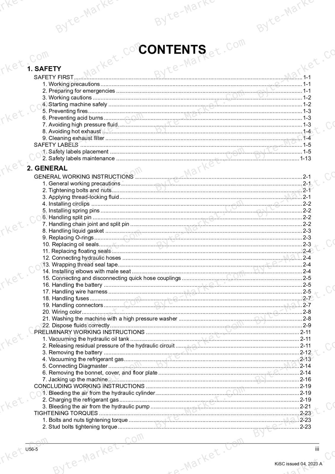
- 1. SAFETY — p. 20
- SAFETY FIRST — p. 21
- 1. Working precautions — p. 21
- 2. Preparing for emergencies — p. 21
- 3. Working cautions — p. 22
- 4. Starting machine safely — p. 22
- 5. Preventing fires — p. 23
- 6. Preventing acid burns — p. 23
- 7. Avoiding high pressure fluid — p. 23
- 8. Avoiding hot exhaust — p. 24
- 9. Cleaning exhaust filter — p. 24
- SAFETY LABELS — p. 25
- 1. Safety labels placement — p. 25
- 2. Safety labels maintenance — p. 33
- SAFETY FIRST — p. 21
- 2. GENERAL — p. 34
- GENERAL WORKING INSTRUCTIONS — p. 35
- 1. General working precautions — p. 35
- 2. Tightening bolts and nuts — p. 35
- 3. Applying thread-locking fluid — p. 35
- 4. Installing circlips — p. 36
- 5. Installing spring pins — p. 36
- 6. Handling split pin — p. 36
- 7. Handling chain joint and split pin — p. 36
- 8. Handling liquid gasket — p. 37
- 9. Replacing O-rings — p. 37
- 10. Replacing oil seals — p. 37
- 11. Replacing floating seals — p. 38
- 12. Connecting hydraulic hoses — p. 38
- 13. Wrapping thread seal tape — p. 38
- 14. Installing elbows with male seat — p. 38
- 15. Connecting and disconnecting quick hose couplings — p. 39
- 16. Handling the battery — p. 39
- 17. Handling wire harness — p. 39
- 18. Handling fuses — p. 41
- 19. Handling connectors — p. 41
- 20. Wiring color — p. 42
- 21. Washing the machine with a high pressure washer — p. 42
- 22. Dispose fluids correctly — p. 43
- PRELIMINARY WORKING INSTRUCTIONS — p. 45
- 1. Vacuuming the hydraulic oil tank — p. 45
- 2. Releasing residual pressure of the hydraulic circuit — p. 45
- 3. Removing the battery — p. 46
- 4. Vacuuming the refrigerant gas — p. 47
- 5. Connecting Diagmaster — p. 48
- 6. Removing the bonnet, cover, and floor plate — p. 48
- 7. Jacking up the machine — p. 50
- CONCLUDING WORKING INSTRUCTIONS — p. 53
- 1. Bleeding the air from the hydraulic cylinder — p. 53
- 2. Charging the refrigerant gas — p. 53
- 3. Bleeding the air from the hydraulic pump — p. 55
- TIGHTENING TORQUES — p. 57
- 1. Bolts and nuts tightening torque — p. 57
- 2. Stud bolts tightening torque — p. 57
- 3. Hydraulic hose fitting tightening torque — p. 58
- 4. Hydraulic hoses tightening torque (taper thread) — p. 58
- 5. Locknuts of adapters with O-ring tightening torque (straight thread) — p. 58
- 6. Adapters tightening torque (taper thread) — p. 59
- 7. Hose clamps tightening torque — p. 59
- GENERAL MACHINE INFORMATION — p. 61
- 1. Machine model identification — p. 61
- 2. Engine model identification — p. 61
- 3. DPF muffler model identification — p. 62
- 4. Injector code identification — p. 63
- 5. Specifications — p. 64
- 6. Machine dimensions — p. 68
- 7. Machine mass table — p. 69
- GENERAL ELECTRICAL INFORMATION — p. 71
- 1. Electrical circuit general description — p. 71
- 1.1 Electrical circuit diagram description — p. 71
- 1.2 Electrical circuit diagram unit symbol — p. 71
- 1.3 Electrical wiring color coding — p. 72
- 1.4 Electrical wiring clamp — p. 72
- 1.5 Bus description — p. 73
- 1.6 Composite terminal description — p. 73
- 2. Connector — p. 73
- 2.1 Connector handling precaution — p. 73
- 2.2 Connector diagram description — p. 73
- 1. Electrical circuit general description — p. 71
- TRANSPORTING THE MACHINE — p. 75
- 1. Loading and unloading the machine on a truck — p. 75
- 2. Towing the inoperable machine — p. 76
- SPECIAL JIGS AND TOOLS — p. 77
- 1. Engine compression pressure measuring kit — p. 77
- 2. Overload relief valve measuring kit — p. 79
- 3. Universal joint tightening jig — p. 80
- 4. Hydraulic cylinder special jigs — p. 81
- 5. Manifold gauge — p. 84
- 6. Charging hoses — p. 84
- 7. Refrigerant gas vacuum machine — p. 84
- 8. Refrigerant gas leak tester — p. 85
- 9. Refrigerant gas canister — p. 85
- GENERAL WORKING INSTRUCTIONS — p. 35
- 3. MAINTENANCE — p. 86
- MAINTENANCE INTERVALS TABLE — p. 87
- LUBRICANT QUANTITY — p. 93
- RECOMMENDED LUBRICANTS — p. 95
- DAILY CHECK — p. 97
- 1. Walk-around inspection — p. 97
- 2. Cleaning the dust valve — p. 97
- 3. Checking the engine oil level — p. 97
- 4. Checking the coolant level — p. 97
- 5. Checking the radiator and A/C condenser — p. 98
- 6. Checking the air conditioning belt and fan belt — p. 98
- 7. Checking the exhaust system leakage — p. 99
- 8. Checking the hydraulic oil level — p. 100
- 9. Checking the water separator — p. 100
- 10. Greasing the lubrication points — p. 101
- 11. Checking the fuel level — p. 102
- 12. Checking the washer liquid level — p. 102
- 13. Checking the engine and electrical wiring — p. 103
- EVERY 50 HOURS — p. 105
- 1. Draining the water from the fuel tank — p. 105
- 2. Checking the battery — p. 105
- 3. Greasing the swivel gear — p. 107
- 4. Checking and adjusting the track tension — p. 107
- 5. Cleaning the water separator — p. 109
- INITIAL 50 HOURS / EVERY 500 HOURS — p. 111
- 1. Replacing the travel motor gear oil — p. 111
- EVERY 150 HOURS — p. 113
- 1. Checking and cleaning the air conditioning filter — p. 113
- EVERY 200 HOURS — p. 115
- 1. Greasing the swivel bearing — p. 115
- 2. Checking and cleaning the engine air cleaner elements — p. 115
- 3. Checking the intake air line — p. 116
- 4. Checking the fuel line — p. 116
- EVERY 250 HOURS — p. 117
- 1. Adjusting the air conditioning belt and fan belt — p. 117
- 2. Greasing the pilot valve linkage — p. 118
- 3. Checking the radiator hoses and clamps — p. 118
- EVERY 500 HOURS — p. 121
- 1. Replacing the water separator element — p. 121
- 2. Replacing the engine oil and engine oil filter — p. 121
- 3. Replacing the fuel filter — p. 122
- 4. Replacing the hydraulic oil tank breather filter — p. 123
- 5. Replacing the air conditioning filter — p. 124
- EVERY 1000 HOURS — p. 125
- 1. Replacing the return filter — p. 125
- 2. Replacing the pilot filter — p. 126
- 3. Replacing the hydraulic oil and suction filter — p. 127
- 4. Replacing the engine air cleaner elements — p. 128
- 5. Checking the valve clearance — p. 129
- 6. Replacing the pilot line filter — p. 134
- EVERY 1500 HOURS — p. 137
- 1. Replacing the oil separator element — p. 137
- 2. Checking the EGR cooler — p. 137
- 3. Checking the injector — p. 138
- EVERY 2000 HOURS — p. 139
- 1. Replacing the engine oil in the front idler and track roller — p. 139
- 2. Checking the alternator — p. 140
- 3. Checking the starter motor — p. 140
- EVERY 3000 HOURS — p. 143
- 1. Checking the EGR valve — p. 143
- EVERY 6000 HOURS — p. 145
- 1. Replacing the DPF muffler — p. 145
- EVERY 1 YEAR — p. 147
- 1. Safety inspection — p. 147
- 2. Checking the intake air line — p. 147
- 3. Checking the DPF muffler — p. 147
- 4. Checking the EGR and EGR piping — p. 148
- 5. Checking the air conditioning and heater hoses — p. 149
- 6. Electric lines and connections — p. 150
- 7. Checking the refrigerant — p. 150
- EVERY 2 YEARS — p. 151
- 1. Replacing the air conditioning and heater hoses — p. 151
- 2. Replacing the radiator hoses and clamps — p. 152
- 3. Replacing the fuel line — p. 153
- 4. Replacing the intake air line — p. 153
- 5. Changing the coolant — p. 154
- 6. Replacing the oil separator rubber piping — p. 155
- 7. Replacing the DPF differential pressure sensor rubber piping — p. 155
- 8. Replacing the EGR cooler hose — p. 156
- 9. Replacing the hydraulic hoses — p. 156
- 4. MACHINE BODY — p. 157
- MECHANISM — p. 158
- 1. Machine device layout — p. 158
- 2. Bucket — p. 160
- 2.1 Bucket dimensions — p. 160
- 3. Arm — p. 162
- 3.1 Arm dimensions — p. 162
- 4. Boom — p. 164
- 4.1 Boom dimensions — p. 164
- 5. Blade — p. 166
- 5.1 Blade dimensions — p. 166
- 6. Rubber track — p. 166
- 6.1 Rubber track dimensions — p. 166
- 7. Steel track — p. 166
- 7.1 Steel track dimensions — p. 166
- 8. Front idler — p. 167
- 8.1 Front idler dimensions — p. 167
- 9. Sprocket — p. 167
- 9.1 Sprocket dimensions — p. 167
- 10. Track roller — p. 168
- 10.1 Track roller dimensions — p. 168
- 11. Carrier roller — p. 168
- 11.1 Carrier roller dimensions — p. 168
- 12. Pins, bushings, and shims — p. 169
- 12.1 Pin, bushing, and shim dimensions — p. 169
- SERVICING — p. 176
- 1. Service specifications — p. 176
- 1.1 Service specifications for the machine body — p. 176
- 2. Testing — p. 179
- 2.1 Measuring the front attachment horizontal play — p. 179
- 2.2 Measuring the swivel bearing vertical play — p. 180
- 2.3 Measuring the swing bracket vertical clearance — p. 181
- 2.4 Measuring the operating force for levers and pedals — p. 181
- 3. Repairing — p. 182
- 3.1 Bucket — p. 182
- 3.1.1 Removing the bucket — p. 182
- 3.2 Arm — p. 182
- 3.2.1 Removing the arm — p. 182
- 3.3 Boom — p. 184
- 3.3.1 Removing the boom — p. 184
- 3.4 Blade — p. 187
- 3.4.1 Removing the blade — p. 187
- 3.5 Swing bracket — p. 188
- 3.5.1 Removing the swing bracket — p. 188
- 3.6 Counterweight — p. 189
- 3.6.1 Removing and installing the counterweight — p. 189
- 3.7 Seat — p. 190
- 3.7.1 Removing and installing the seat — p. 190
- 3.8 Cabin — p. 192
- 3.8.1 Removing and installing the cabin — p. 192
- 3.9 Lever lock — p. 196
- 3.9.1 Removing and installing the lever lock — p. 196
- 3.10 Swivel bearing — p. 200
- 3.10.1 Removing and installing the swivel bearing — p. 200
- 3.11 Rubber track — p. 202
- 3.11.1 Removing and installing the rubber track — p. 202
- 3.12 Steel track — p. 204
- 3.12.1 Removing and installing the steel track — p. 204
- 3.13 Front idler — p. 207
- 3.13.1 Removing the front idler — p. 207
- 3.13.2 Front idler components — p. 208
- 3.13.3 Disassembling the front idler — p. 208
- 3.13.4 Assembling the front idler — p. 209
- 3.14 Tension spring — p. 211
- 3.14.1 Removing and installing the tension spring — p. 211
- 3.15 Grease cylinder — p. 212
- 3.15.1 Removing the grease cylinder — p. 212
- 3.16 Track roller — p. 212
- 3.16.1 Removing and installing the track roller — p. 212
- 3.16.2 Track roller components — p. 213
- 3.16.3 Disassembling the track roller — p. 213
- 3.16.4 Assembling the track roller — p. 214
- 3.17 Carrier roller — p. 215
- 3.17.1 Removing and installing the carrier roller — p. 215
- 3.1 Bucket — p. 182
- 1. Service specifications — p. 176
- MECHANISM — p. 158
- 5. ENGINE — p. 217
- MECHANISM — p. 218
- 1. Engine device layout — p. 218
- 2. Engine specifications — p. 223
- 3. Engine dimensions — p. 225
- 4. Engine performance curves — p. 226
- 5. Lubricating system — p. 228
- 5.1 Lubricating system general description — p. 228
- 6. Cooling system — p. 228
- 6.1 Cooling system general description — p. 228
- 7. Intake air system — p. 229
- 7.1 Intake air system general description — p. 229
- 8. EGR system — p. 230
- 8.1 EGR system general description — p. 230
- 9. Common rail system — p. 231
- 9.1 Common rail system general description — p. 231
- 10. Aftertreatment system — p. 232
- 10.1 Aftertreatment system general description — p. 232
- 10.2 DPF regeneration control — p. 233
- SERVICING — p. 238
- 1. Troubleshooting — p. 238
- 1.1 Engine troubleshooting — p. 238
- 2. Service specifications — p. 240
- 2.1 Service specifications for the engine — p. 240
- 3. Testing — p. 240
- 3.1 Measuring engine compression pressure — p. 240
- 3.2 Measuring engine oil pressure — p. 240
- 4. Repairing — p. 241
- 4.1 Fuel hose and tank — p. 241
- 4.1.1 Removing and installing the fuel tank — p. 241
- 4.1.2 Fuel hose routing — p. 245
- 4.2 Engine — p. 250
- 4.2.1 Removing and installing the engine — p. 250
- 4.2.2 Removing the alternator — p. 258
- 4.2.3 Removing the starter motor — p. 259
- 4.2.4 Removing and installing the rail — p. 259
- 4.2.5 Removing and installing the supply pump — p. 261
- 4.2.6 Removing and installing the injector — p. 263
- 4.2.7 Removing the EGR valve — p. 269
- 4.2.8 Removing the EGR cooler — p. 270
- 4.2.9 Removing the throttle valve — p. 271
- 4.3 Radiator — p. 273
- 4.3.1 Removing and installing the radiator — p. 273
- 4.4 DPF muffler — p. 277
- 4.4.1 Removing and installing the DPF muffler — p. 277
- 4.1 Fuel hose and tank — p. 241
- 1. Troubleshooting — p. 238
- MECHANISM — p. 218
- 6. HYDRAULIC SYSTEM — p. 280
- MECHANISM — p. 281
- 1. Hydraulic device layout — p. 281
- 2. Hydraulic system general description — p. 283
- 2.1 Load sensing system general description — p. 283
- 2.2 Pilot control system general description — p. 285
- 3. Hydraulic pump — p. 287
- 3.1 Hydraulic pump specifications — p. 287
- 3.2 Hydraulic pump hydraulic circuit — p. 288
- 3.3 Piston pump P-Q performance — p. 289
- 3.4 Hydraulic pump function and structure — p. 290
- 3.4.1 Piston pump working principles — p. 290
- 3.4.2 Horsepower control — p. 291
- 3.4.3 Flow control (load sensing control) — p. 293
- 3.4.4 Standby flow — p. 295
- 3.4.5 Gain control — p. 296
- 4. Control valve — p. 298
- 4.1 Control valve specifications — p. 298
- 4.2 Control valve hydraulic circuit — p. 302
- 4.3 Control valve spool shift performance — p. 303
- 4.4 Control valve function and structure — p. 304
- 4.4.1 Main relief valve — p. 304
- 4.4.2 Overload relief valve — p. 304
- 4.4.3 Boom lowering valve — p. 306
- 4.4.4 Unload valve — p. 307
- 4.4.5 High pressure selector function — p. 309
- 4.4.6 Pressure compensator valve — p. 311
- 4.4.7 Arm regeneration — p. 313
- 4.4.8 Independent travel valve — p. 314
- 4.4.9 Auto-idle signal circuit — p. 318
- 5. Swivel motor — p. 319
- 5.1 Swivel motor specifications — p. 319
- 5.2 Swivel motor hydraulic circuit — p. 320
- 5.3 Swivel motor function and structure — p. 320
- 5.3.1 Swivel motor working principles — p. 320
- 5.3.2 Shockless function — p. 321
- 5.3.3 Swivel motor parking brake — p. 321
- 5.3.4 Make-up circuit — p. 322
- 6. Travel motor — p. 323
- 6.1 Travel motor specifications — p. 323
- 6.2 Travel motor hydraulic circuit — p. 324
- 6.3 Travel motor function and structure — p. 325
- 6.3.1 Travel motor working principles — p. 325
- 6.3.2 Counterbalance valve — p. 325
- 6.3.3 Anti-cavitation valve — p. 327
- 6.3.4 Automatic deceleration — p. 329
- 6.3.5 Travel motor parking brake — p. 331
- 7. Hydraulic cylinder — p. 332
- 7.1 Hydraulic cylinder specifications — p. 332
- 8. Swivel joint — p. 333
- 8.1 Swivel joint specifications — p. 333
- 9. Pilot control valve — p. 335
- 9.1 Pilot control valve specifications — p. 335
- 9.2 Pilot control valve performance diagram — p. 336
- 9.3 Pilot control valve function and structure — p. 337
- 10. Travel control valve — p. 337
- 10.1 Travel control valve specifications — p. 337
- 10.2 Travel control valve performance diagram — p. 338
- 10.3 Travel control valve function and structure — p. 338
- 11. Swing control valve — p. 339
- 11.1 Swing control valve specifications — p. 339
- 11.2 Swing control valve performance diagram — p. 339
- 11.3 Swing control valve function and structure — p. 340
- 12. Blade control valve — p. 340
- 12.1 Blade control valve specifications — p. 340
- 12.2 Blade control valve performance diagram — p. 341
- 12.3 Blade control valve function and structure — p. 342
- 13. Unload valve — p. 344
- 13.1 Unload valve specifications — p. 344
- 13.2 Unload valve function and structure — p. 345
- 13.2.1 Unload valve working principles — p. 345
- 14. Proportional valve — p. 346
- 14.1 Proportional valve specifications — p. 346
- 14.2 Proportional valve performance diagram — p. 347
- 14.3 Proportional valve function and structure — p. 347
- 14.3.1 Proportional valve working principles — p. 347
- 15. Boom holding valve — p. 348
- 15.1 Boom holding valve specifications — p. 348
- 15.2 Boom holding valve function and structure — p. 348
- 15.2.1 Boom holding valve working principles — p. 348
- 16. Arm holding valve — p. 350
- 16.1 Arm holding valve specifications — p. 350
- 16.2 Arm holding valve function and structure — p. 350
- 16.2.1 Arm holding valve working principles — p. 350
- 17. Mechanical third line valve — p. 352
- 17.1 Mechanical third line valve specifications — p. 352
- 18. Hydraulic third line valve — p. 352
- 18.1 Hydraulic third line valve specifications — p. 352
- 19. Third line solenoid valve — p. 353
- 19.1 Third line solenoid valve specifications — p. 353
- 19.2 Third line solenoid valve control diagram — p. 354
- 19.3 Third line solenoid valve function and structure — p. 354
- 19.3.1 Third line solenoid valve working principles — p. 354
- SERVICING — p. 355
- 1. Troubleshooting — p. 355
- 1.1 Hydraulic troubleshooting for front attachment — p. 355
- 1.2 Hydraulic troubleshooting for swivel — p. 357
- 1.3 Hydraulic troubleshooting for traveling — p. 358
- 2. Service specifications — p. 359
- 2.1 Service specifications for the hydraulic system — p. 359
- 3. Testing — p. 361
- 3.1 Measuring the hydraulic devices — p. 361
- 3.1.1 Measuring the boom cylinder speed — p. 361
- 3.1.2 Measuring the arm cylinder speed — p. 362
- 3.1.3 Measuring the bucket cylinder speed — p. 362
- 3.1.4 Measuring the blade cylinder speed — p. 362
- 3.1.5 Measuring the swing cylinder speed — p. 363
- 3.1.6 Measuring the swivel speed — p. 363
- 3.1.7 Measuring the travel speed — p. 364
- 3.1.8 Measuring the cylinder internal leakage — p. 364
- 3.1.9 Measuring the travel motor internal leakage — p. 365
- 3.1.10 Measuring the swivel motor internal leakage — p. 366
- 3.1.11 Testing the travel straightness — p. 366
- 3.2 Measuring the hydraulic pump — p. 368
- 3.2.1 Measuring the piston pump P-Q performance — p. 368
- 3.2.2 Measuring the AUX flow rate — p. 371
- 3.3 Measuring the control valve — p. 375
- 3.3.1 Measuring the main relief valve pressure — p. 375
- 3.3.2 Measuring the overload relief valve — p. 376
- 3.4 Measuring the swivel motor — p. 378
- 3.4.1 Measuring the swivel motor overload relief valve pressure — p. 378
- 3.4.2 Measuring the swivel motor drain — p. 379
- 3.5 Measuring the travel motor — p. 380
- 3.5.1 Measuring the travel motor drain — p. 380
- 3.6 Measuring the pilot control valve — p. 381
- 3.6.1 Measuring the pilot primary pressure — p. 381
- 3.6.2 Measuring the pilot secondary pressure — p. 382
- 3.7 Measuring the holding valve — p. 383
- 3.7.1 Measuring the relief pressure — p. 383
- 3.1 Measuring the hydraulic devices — p. 361
- 4. Repairing — p. 384
- 4.1 Hydraulic pump — p. 384
- 4.1.1 Removing and installing the hydraulic pump — p. 384
- 4.1.2 Hydraulic pump components — p. 387
- 4.1.3 Disassembling the piston pump — p. 388
- 4.1.4 Assembling the piston pump — p. 392
- 4.1.5 Installing adapters for the hydraulic pump — p. 400
- 4.1.6 Removing and installing the pump coupling — p. 401
- 4.2 Control valve — p. 402
- 4.2.1 Removing and installing the control valve — p. 402
- 4.2.2 Control valve components — p. 404
- 4.2.3 Disassembling and assembling the control valve — p. 411
- 4.2.4 Installing adapters for the control valve — p. 412
- 4.3 Swivel motor — p. 415
- 4.3.1 Removing and installing the swivel motor — p. 415
- 4.3.2 Swivel motor components — p. 417
- 4.3.3 Disassembling the swivel motor — p. 418
- 4.3.4 Assembling the swivel motor — p. 423
- 4.3.5 Installing adapters for the swivel motor — p. 430
- 4.4 Travel motor — p. 430
- 4.4.1 Removing and installing the travel motor — p. 430
- 4.4.2 Travel motor components — p. 432
- 4.4.3 Disassembling the travel motor — p. 433
- 4.4.4 Assembling the travel motor — p. 441
- 4.5 Hydraulic cylinder — p. 455
- 4.5.1 Boom, arm, and bucket cylinders — p. 455
- 4.5.2 Blade and swing cylinders — p. 466
- 4.5.3 Measuring the hydraulic cylinder — p. 468
- 4.6 Swivel joint — p. 469
- 4.6.1 Removing and installing the swivel joint — p. 469
- 4.6.2 Installing adapters for the swivel joint — p. 472
- 4.7 Pilot control valve — p. 473
- 4.7.1 Removing and installing the pilot control valve — p. 473
- 4.7.2 Pilot control valve components — p. 477
- 4.7.3 Disassembling the pilot control valve — p. 477
- 4.7.4 Assembling the pilot control valve — p. 480
- 4.7.5 Installing adapters for the pilot control valve — p. 482
- 4.8 Travel control valve — p. 483
- 4.8.1 Removing and installing the travel control valve — p. 483
- 4.8.2 Travel control valve components — p. 486
- 4.8.3 Disassembling the travel control valve — p. 486
- 4.8.4 Assembling the travel control valve — p. 489
- 4.8.5 Installing adapters for the travel control valve — p. 493
- 4.9 Swing control valve — p. 493
- 4.9.1 Removing and installing the swing control valve — p. 493
- 4.9.2 Swing control valve components — p. 494
- 4.9.3 Disassembling the swing control valve — p. 494
- 4.9.4 Assembling the swing control valve — p. 498
- 4.9.5 Installing adapters for the swing control valve — p. 501
- 4.10 Blade control valve — p. 502
- 4.10.1 Removing and installing the blade control valve — p. 502
- 4.10.2 Blade control valve components — p. 505
- 4.10.3 Disassembling the blade control valve — p. 505
- 4.10.4 Assembling the blade control valve — p. 507
- 4.10.5 Installing adapters for the blade control valve — p. 510
- 4.11 Unload valve — p. 510
- 4.11.1 Removing and installing the unload valve — p. 510
- 4.11.2 Unload valve components — p. 511
- 4.11.3 Disassembling and assembling the unload valve — p. 512
- 4.11.4 Installing adapters for the unload valve — p. 514
- 4.12 Proportional valve — p. 515
- 4.12.1 Removing and installing the proportional valve — p. 515
- 4.12.2 Proportional valve components — p. 516
- 4.12.3 Disassembling and assembling the proportional valve — p. 516
- 4.12.4 Installing adapters for the proportional valve — p. 517
- 4.13 Boom holding valve — p. 517
- 4.13.1 Removing and installing the boom holding valve — p. 517
- 4.13.2 Boom holding valve components — p. 518
- 4.13.3 Disassembling the boom holding valve — p. 519
- 4.13.4 Assembling the boom holding valve — p. 520
- 4.13.5 Installing adapter layout for the boom holding valve — p. 522
- 4.14 Arm holding valve — p. 522
- 4.14.1 Removing and installing the arm holding valve — p. 522
- 4.14.2 Arm holding valve components — p. 524
- 4.14.3 Disassembling the arm holding valve — p. 524
- 4.14.4 Assembling the arm holding valve — p. 526
- 4.14.5 Installing adapter layout for the arm holding valve — p. 527
- 4.15 Mechanical third line valve — p. 528
- 4.15.1 Removing and installing the mechanical third line valve — p. 528
- 4.15.2 Disassembling and assembling the mechanical third line valve — p. 528
- 4.15.3 Installing adapters for the mechanical third line valve — p. 529
- 4.16 Hydraulic third line valve — p. 529
- 4.16.1 Removing and installing the hydraulic third line valve — p. 529
- 4.16.2 Disassembling and assembling the hydraulic third line valve — p. 529
- 4.16.3 Installing adapters for the hydraulic third line valve — p. 530
- 4.17 Third line solenoid valve — p. 531
- 4.17.1 Removing and installing the third line solenoid valve — p. 531
- 4.17.2 Disassembling and assembling the third line solenoid valve — p. 532
- 4.17.3 Installing adapters for the third line solenoid valve — p. 532
- 4.18 Hydraulic oil tank — p. 532
- 4.18.1 Removing and installing the hydraulic oil tank — p. 532
- 4.19 Hydraulic hose — p. 539
- 4.19.1 Length description of hydraulic hoses — p. 539
- 4.19.2 Metal fittings of hydraulic hoses — p. 540
- 4.19.3 Delivery hose routing — p. 541
- 4.19.4 Front hose routing — p. 542
- 4.19.5 Swivel and swing hoses routing — p. 544
- 4.19.6 Travel and blade hoses routing — p. 545
- 4.19.7 Drain hose routing — p. 546
- 4.19.8 Pilot hose routing (delivery, drain) — p. 548
- 4.19.9 Pilot hose routing (operation) — p. 553
- 4.1 Hydraulic pump — p. 384
- 1. Troubleshooting — p. 355
- MECHANISM — p. 281
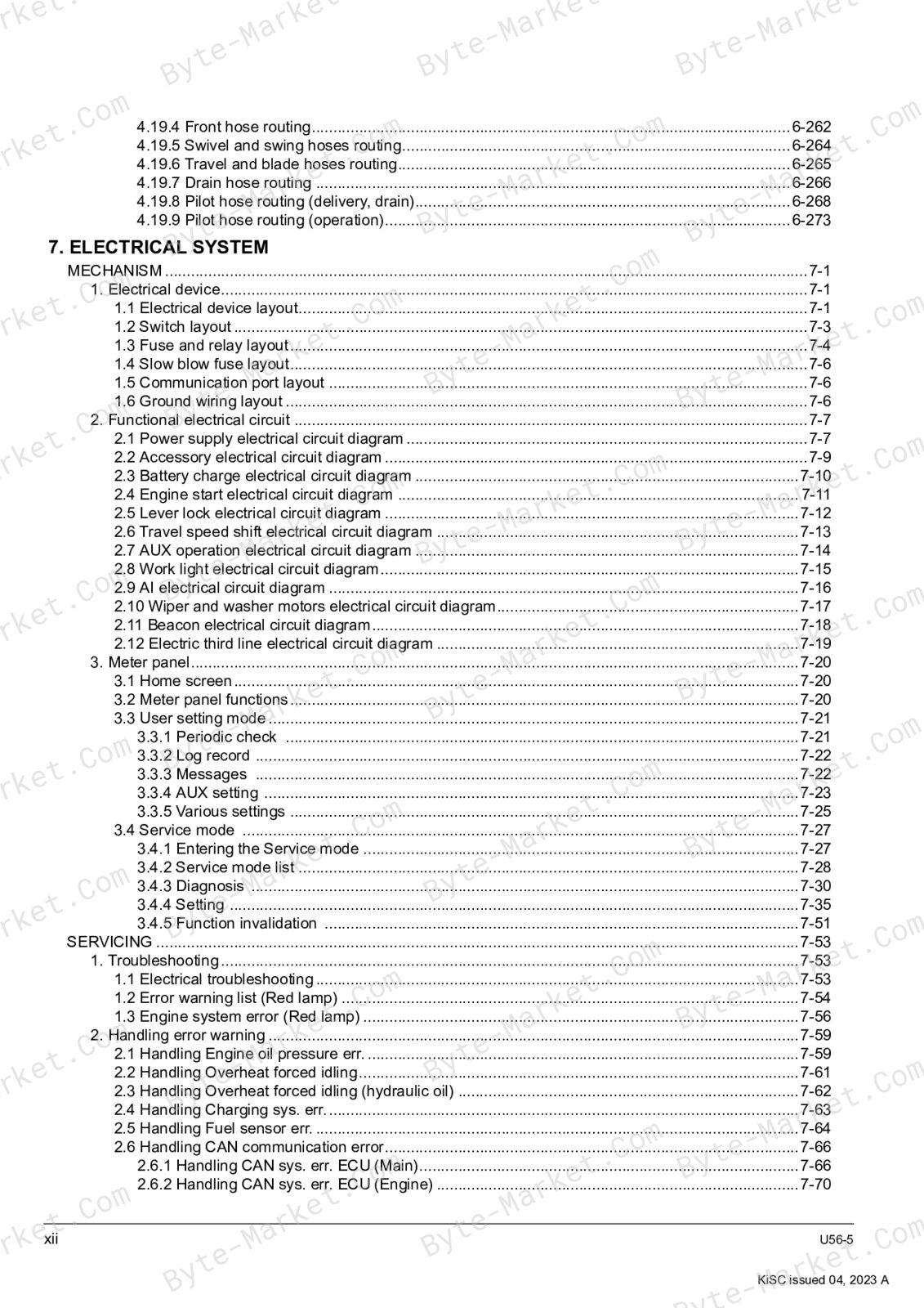
- 7. ELECTRICAL SYSTEM — p. 557
- MECHANISM — p. 558
- 1. Electrical device — p. 558
- 1.1 Electrical device layout — p. 558
- 1.2 Switch layout — p. 560
- 1.3 Fuse and relay layout — p. 561
- 1.4 Slow blow fuse layout — p. 563
- 1.5 Communication port layout — p. 563
- 1.6 Ground wiring layout — p. 563
- 2. Functional electrical circuit — p. 564
- 2.1 Power supply electrical circuit diagram — p. 564
- 2.2 Accessory electrical circuit diagram — p. 566
- 2.3 Battery charge electrical circuit diagram — p. 567
- 2.4 Engine start electrical circuit diagram — p. 568
- 2.5 Lever lock electrical circuit diagram — p. 569
- 2.6 Travel speed shift electrical circuit diagram — p. 570
- 2.7 AUX operation electrical circuit diagram — p. 571
- 2.8 Work light electrical circuit diagram — p. 572
- 2.9 AI electrical circuit diagram — p. 573
- 2.10 Wiper and washer motors electrical circuit diagram — p. 574
- 2.11 Beacon electrical circuit diagram — p. 575
- 2.12 Electric third line electrical circuit diagram — p. 576
- 3. Meter panel — p. 577
- 3.1 Home screen — p. 577
- 3.2 Meter panel functions — p. 577
- 3.3 User setting mode — p. 578
- 3.3.1 Periodic check — p. 578
- 3.3.2 Log record — p. 579
- 3.3.3 Messages — p. 579
- 3.3.4 AUX setting — p. 580
- 3.3.5 Various settings — p. 582
- 3.4 Service mode — p. 584
- 3.4.1 Entering the Service mode — p. 584
- 3.4.2 Service mode list — p. 585
- 3.4.3 Diagnosis — p. 587
- 3.4.4 Setting — p. 592
- 3.4.5 Function invalidation — p. 608
- 1. Electrical device — p. 558
- SERVICING — p. 610
- 1. Troubleshooting — p. 610
- 1.1 Electrical troubleshooting — p. 610
- 1.2 Error warning list (Red lamp) — p. 611
- 1.3 Engine system error (Red lamp) — p. 613
- 2. Handling error warning — p. 616
- 2.1 Handling Engine oil pressure err — p. 616
- 2.2 Handling Overheat forced idling — p. 618
- 2.3 Handling Overheat forced idling (hydraulic oil) — p. 619
- 2.4 Handling Charging sys. err — p. 620
- 2.5 Handling Fuel sensor err — p. 621
- 2.6 Handling CAN communication error — p. 623
- 2.6.1 Handling CAN sys. err. ECU (Main) — p. 623
- 2.6.2 Handling CAN sys. err. ECU (Engine) — p. 627
- 2.6.3 Handling CAN sys. err. ECU (Sub) — p. 631
- 2.6.4 Handling CAN sys. err. Keypad — p. 635
- 2.6.5 Handling CAN sys. err. ECU (Meter panel) — p. 637
- 2.7 Handling 2-speed sys. err — p. 641
- 2.8 Handling AUX1 system error — p. 643
- 2.8.1 Handling AUX1 sys. err. (AUX1 knob switch) — p. 643
- 2.8.2 Handling AUX1 sys. err. (AUX1 proportional solenoids LH and RH) — p. 644
- 2.9 Handling AUX2 system error — p. 645
- 2.9.1 Handling AUX2/Thumb sys. err. (AUX2 thumb knob switch) — p. 645
- 2.9.2 Handling AUX2/Thumb sys. err. (AUX2 proportional solenoids LH and RH) — p. 647
- 2.10 Handling Overvoltage — p. 648
- 2.11 Handling Auto idle sys. err — p. 649
- 2.12 Handling Lever lock sys. err — p. 651
- 2.13 Handling External 5V sys. err — p. 653
- 2.14 Handling Overload warning err — p. 655
- 2.15 Handling Hyd. temp. sensor err — p. 656
- 2.16 Handling 3-way valve sys. err — p. 658
- 1. Troubleshooting — p. 610
- MECHANISM — p. 558
- 8. AIR CONDITIONING AND HEATER SYSTEM — p. 660
- MECHANISM — p. 661
- 1. Air conditioning device layout — p. 661
- 2. Air conditioning and heater system general description — p. 663
- 3. Compressor — p. 664
- 3.1 Compressor specifications — p. 664
- 3.2 Compressor function and structure — p. 665
- 3.2.1 Compressor working principles — p. 665
- 3.2.2 Magnetic clutch pulley — p. 665
- 3.2.3 Safety valve — p. 665
- 3.2.4 Temperature switch — p. 666
- 4. Air conditioning unit — p. 667
- 4.1 Air conditioning unit specifications — p. 667
- 4.2 Air conditioning unit function and structure — p. 669
- 4.2.1 Evaporator — p. 669
- 4.2.2 Heater core — p. 669
- 4.2.3 Blower — p. 669
- 4.2.4 Blower resistor — p. 669
- 4.2.5 Expansion valve — p. 670
- 4.2.6 Thermostat — p. 670
- 4.2.7 Servomotor — p. 671
- 4.2.8 Heater valve — p. 671
- 5. Condenser — p. 671
- 5.1 Condenser specifications — p. 671
- 5.2 Condenser function and structure — p. 672
- 6. Receiver — p. 672
- 6.1 Receiver specifications — p. 672
- 6.2 Receiver function and structure — p. 673
- 7. Pressure switch — p. 673
- 7.1 Pressure switch specifications — p. 673
- 7.2 Pressure switch function and structure — p. 673
- 8. Heater unit — p. 675
- 8.1 Heater unit specifications — p. 675
- 8.2 Heater unit function and structure — p. 677
- 8.2.1 Heater core — p. 677
- 8.2.2 Blower — p. 677
- 8.2.3 Blower resistor — p. 677
- 8.2.4 Servomotor — p. 677
- 8.2.5 Heater valve — p. 678
- SERVICING — p. 679
- 1. Troubleshooting — p. 679
- 1.1 Air conditioning troubleshooting — p. 679
- 2. Service specifications — p. 683
- 2.1 Service specifications for air conditioning and heater system — p. 683
- 3. Testing — p. 683
- 3.1 Checking the refrigerant liquid — p. 683
- 3.2 Measuring the refrigerant pressure — p. 683
- 3.3 Checking the fan switch — p. 685
- 3.4 Measuring the magnetic clutch pulley air gap — p. 686
- 3.5 Checking the blower resistor — p. 687
- 4. Repairing — p. 687
- 4.1 Vacuuming the refrigerant — p. 687
- 4.2 Charging the refrigerant — p. 688
- 4.3 Compressor — p. 690
- 4.3.1 Removing and installing the compressor — p. 690
- 4.4 Air conditioning unit — p. 692
- 4.4.1 Removing and installing the air conditioning unit — p. 692
- 4.5 Condenser — p. 721
- 4.5.1 Removing and installing the condenser — p. 721
- 4.6 Receiver — p. 722
- 4.6.1 Removing and installing the receiver — p. 722
- 4.7 Air conditioning and heater hoses — p. 724
- 4.7.1 Air conditioning and heater hose routing — p. 724
- 1. Troubleshooting — p. 679
- MECHANISM — p. 661
- 9. KUBOTA TRACKING SYSTEM — p. 729
- MECHANISM — p. 730
- 1. Kubota Tracking System device layout — p. 730
- 2. Kubota Tracking System general description — p. 731
- 3. Functional electrical circuit — p. 732
- 3.1 Kubota Tracking System electrical circuit diagram — p. 732
- 4. DCU — p. 733
- 4.1 DCU specifications — p. 733
- 5. IPU — p. 734
- 5.1 IPU specifications — p. 734
- SERVICING — p. 736
- 1. Kubota Tracking System lamp conditions — p. 736
- 1.1 GPS indicator lamp (green) condition list — p. 737
- 1.2 External telecommunication indicator lamp (green) condition list — p. 739
- 1.3 Internal telecommunication indicator lamp (red) condition list — p. 741
- 2. Troubleshooting (Kubota Tracking System) — p. 742
- 2.1 Handling CAN communication error between DCU and IPU — p. 742
- 2.2 Handling errors for each ABNORMALITY — p. 744
- 2.2.1 Handling error of updating machine location information — p. 744
- 2.2.2 Handling error of updating machine operation information — p. 744
- 2.2.3 Handling error of updating machine location and operation information — p. 746
- 3. Repairing — p. 749
- 3.1 Removing and installing the Kubota Tracking System — p. 749
- 1. Kubota Tracking System lamp conditions — p. 736
- MECHANISM — p. 730
- 10. APPENDICES — p. 754
- APPENDICES — p. 755
- 1. Servicing information — p. 755
- 1.1 Service specifications for the machine body — p. 755
- 1.2 Service specifications for the engine — p. 758
- 1.3 Service specifications for hydraulic system — p. 758
- 1.3.1 Piston pump P-Q performance — p. 762
- 1.3.2 AUX P-Q performance — p. 763
- 1.4 Service mode — p. 766
- 1.4.1 Default settings — p. 766
- 2. Hydraulic circuit diagram — p. 767
- 3. Wire harness — p. 769
- 1. Servicing information — p. 755
- APPENDICES — p. 755
- User setting mode flow chart — p. 778
- Service mode flow chart — p. 779
- ELECTRICAL CIRCUIT DIAGRAM — p. 784
- 1. SAFETY — p. 20
Capabilities
The source outline indexes maintenance tasks, checking and adjustment, mechanism explanations, servicing instructions, disassembly and assembly, and troubleshooting. Use these source-backed headings to locate the applicable task or system in the source PDF, then confirm model-specific notes, specifications, illustrations, and operating conditions at the relevant page before carrying out service work.
Keep the source's safety sequence, prerequisite steps, labels, units, configuration notes, and footnotes with the selected task; do not apply an isolated value outside the conditions stated in the manual.
Technical reference
Reference tables include torque settings, wear limits, fluid and system capacities, and speed ratings for service checks, adjustment work, and specification lookup. Use the values and conditions in the PDF for the applicable model and procedure.
- Service limits and settings: torque settings and wear limits.
- Fluid reference: fluid and system capacities.
- Machine specifications: speed ratings.
Delivery
This manual is supplied as a digital PDF file and is available for instant download after purchase. No physical media is shipped.
References
Kubota Workshop Manual for Excavator, document code RY911-27935, PDF edition.


No questions found.