
Kubota Diagnostic Manual
Kubota V2607-CR-E4B, V2607-CR-TE4B, V2607-CR-TIE4B (DOC only), V3307-CR-TE4B, and V3307-CR-TIE4B (DOC only) Engine Diagnostic Manual
Document number 9Y110-01991 · English PDF edition · 350 pages
About this manual
Kubota published this Diagnostic Manual for the V2607-CR-E4B, V2607-CR-TE4B, V2607-CR-TIE4B (DOC only), V3307-CR-TE4B, and V3307-CR-TIE4B (DOC only) engines. It provides documented fault finding, diagnostic trouble codes, tests, and technical reference material for those engines.
Use the Manual Contents below to check that the exact fault-code, diagnostic-test, troubleshooting, or reference topic you need is included in this publication.
Manual details
- Manufacturer
- Kubota
- Manual type
- Diagnostic Manual
- Equipment type
- Engine
- Models
- V2607-CR-E4B, V2607-CR-TE4B, V2607-CR-TIE4B (DOC only), V3307-CR-TE4B, and V3307-CR-TIE4B (DOC only)
- Model-specific applicability
- V2607-CR-TIE4B: DOC only; V3307-CR-TIE4B: DOC only
- Document number
- 9Y110-01991
- Publication year
- 2015
- Language
- English
- Page count
- 350
Product highlights
Electrical systems
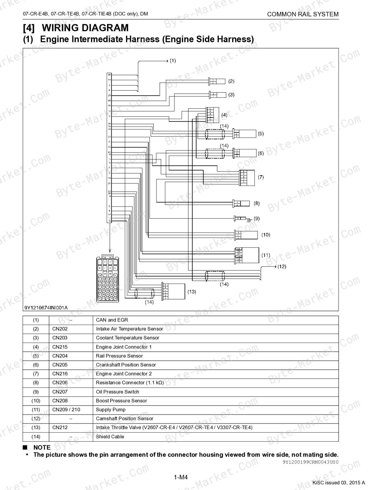
The manual includes wiring diagrams, connector views, and pinouts.
Specifications and settings
The manual includes reference information for speed ratings.
Manual contents
Use these source headings to locate the task or system you need in the PDF.
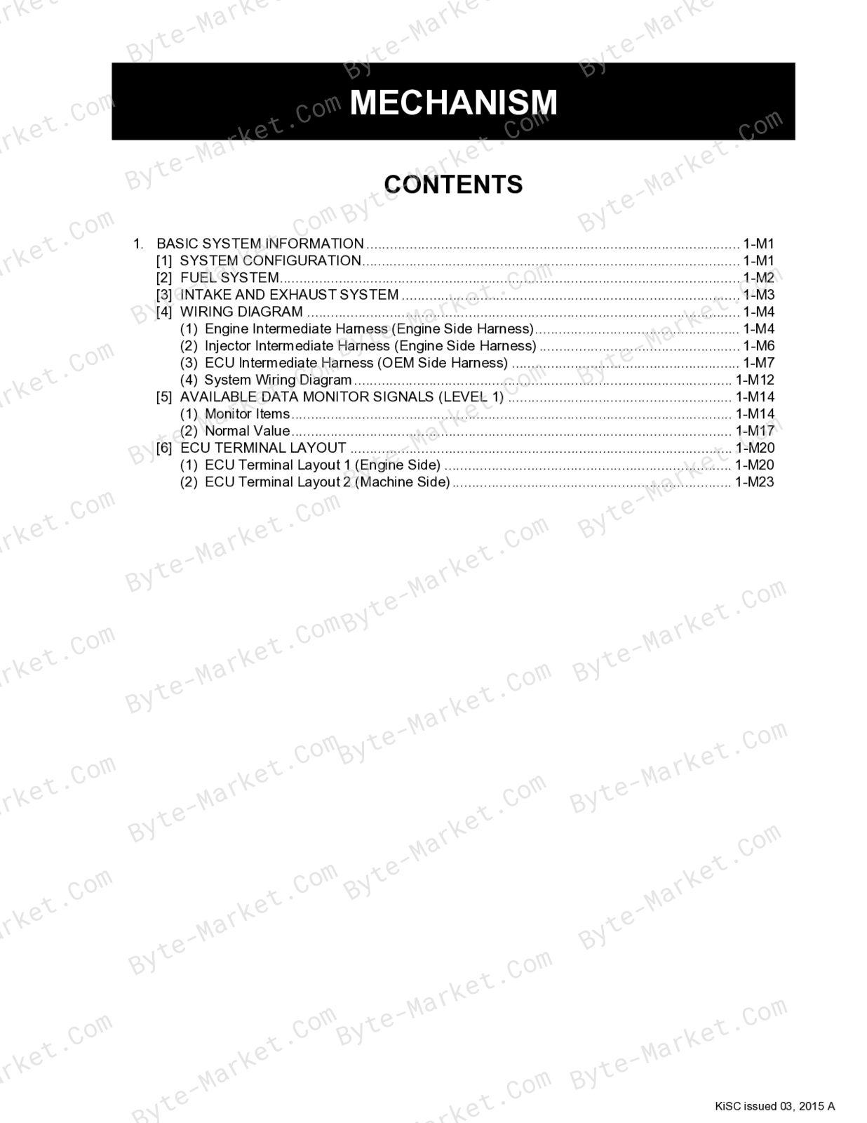
- SAFETY FIRST — p. I-1
- BASIC SYSTEM INFORMATION — p. 1-M1
- [1] SYSTEM CONFIGURATION — p. 1-M1
- [2] FUEL SYSTEM — p. 1-M2
- [3] INTAKE AND EXHAUST SYSTEM — p. 1-M3
- [4] WIRING DIAGRAM — p. 1-M4
- (1) Engine Intermediate Harness (Engine Side Harness) — p. 1-M4
- (2) Injector Intermediate Harness (Engine Side Harness) — p. 1-M6
- (3) ECU Intermediate Harness (OEM Side Harness) — p. 1-M7
- (4) System Wiring Diagram — p. 1-M12
- [5] AVAILABLE DATA MONITOR SIGNALS (LEVEL 1) — p. 1-M14
- (1) Monitor Items — p. 1-M14
- (2) Normal Value — p. 1-M17
- [6] ECU TERMINAL LAYOUT — p. 1-M20
- (1) ECU Terminal Layout 1 (Engine Side) — p. 1-M20
- (2) ECU Terminal Layout 2 (Machine Side) — p. 1-M23
- GENERAL — p. 1-S1
- [1] OVERALL DIAGNOSTIC PROCEDURE — p. 1-S1
- [2] QUESTIONING — p. 1-S2
- [3] LIST OF MALFUNCTION SYMPTOM — p. 1-S5
- [4] ACTIONS FOR NON-REOCCURRING MALFUNCTIONS — p. 1-S6
- DIAGNOSTIC TOOL CONNECTION PROCEDURE — p. 1-S8
- [1] DIAGNOSTIC CONNECTOR POSITIONS — p. 1-S8
- [2] DIAGNOSTIC TOOL CONNECTION PROCEDURE — p. 1-S8
- [3] CHECKING THE COMMUNICATION OPERATION OF THE INTERFACE (DST-i) — p. 1-S9
- [4] CHECKING THE OPERATION OF THE ECU — p. 1-S10
- (1) Starting Diagmaster — p. 1-S10
- (2) DST-i Communication Settings — p. 1-S11
- ACTIVE TEST AND SUPPLY PUMP DIFFERENCE LEARNING — p. 1-S15
- DIAGNOSIS BY MALFUNCTION SYMPTOM — p. 1-S17
- [1] LIST OF MALFUNCTION CAUSES BY SYMPTOM — p. 1-S17
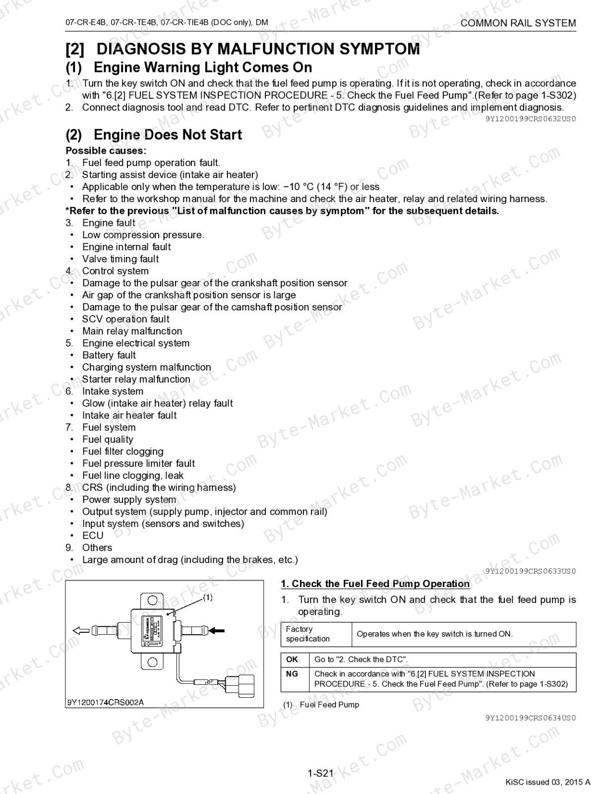
- [2] DIAGNOSIS BY MALFUNCTION SYMPTOM — p. 1-S21
- (1) Engine Warning Light Comes On — p. 1-S21
- (2) Engine Does Not Start — p. 1-S21
- (3) Takes A Long Time Before Engine Starts — p. 1-S25
- (4) Idle Failure — p. 1-S29
- (5) Engine Noise — p. 1-S32
- (6) High fuel consumption — p. 1-S34
- (7) Poor Acceleration (Insufficient Output) — p. 1-S39
- (8) Abnormal Black Smoke Emitted — p. 1-S44
- (9) Abnormal White Smoke Emitted — p. 1-S48
- (10)Engine Stalls On Deceleration — p. 1-S53
- DIAGNOSTIC PROCEDURE BY DTC — p. 1-S57
- [1] DTC LIST — p. 1-S57
- [2] DIAGNOSTIC PROCEDURE BY DTC — p. 1-S120
- (1) NE - G Phase Shift (DTC P0016 / 636-7) — p. 1-S123
- DTC P0073 / 171-3) — p. 1-S124
- (3) Pressure Limiter Emergency Open (DTC P0087 / 633-7) — p. 1-S127
- (4) High Rail Pressure (DTC P0088 / 157-0) — p. 1-S132
- (5) SCV Stuck (DTC P0089 / 1347-7) — p. 1-S137
- (6) Fuel Leak (in High Pressured Fuel System) (DTC P0093 / 1239-1) — p. 1-S142
- (7) Intake Air Volume: Low (DTC P0101 / 132-1) — p. 1-S147
- (8) MAF Sensor Abnormality (DTC P0102 / 132-4, P0103 / 132-3) — p. 1-S148
- (9) Intake Air Temperature: High (Inter Cooler Model Only) (DTC P0111 / 172-0) — p. 1-S150
- (10)Intake Air Temperature Error (DTC P0112 / 172-4, P0113 / 172-3) — p. 1-S151
- (11)Coolant Temperature Sensor Abnormality (DTC P0117 / 110-4, P0118 / 110-3) — p. 1-S154
- (12)Fuel High Temperature (DTC P0181 / 174-0) — p. 1-S157
- (13)Fuel Temperature Sensor Abnormality (DTC P0182 / 174-4, P0183 / 174-3) — p. 1-S158
- (14)Rail Pressure Sensor Abnormality (DTC P0192 / 157-4, P0193 / 157-3) — p. 1-S161
- (15)Injector Charge Voltage: High (DTC P0200 / 523535-0) — p. 1-S165
- P0204 / 652-3) — p. 1-S167
- (17)Engine Overheat (DTC P0217 / 110-0) — p. 1-S170
- (18)Engine Overrun (DTC P0219 / 190-0) — p. 1-S172
- (1) NE - G Phase Shift (DTC P0016 / 636-7) — p. 1-S123
Capabilities
The source outline indexes diagnostic reference and diagnostic tests. Use these source-backed headings to locate the applicable diagnostic task or fault family in the source PDF, then confirm model-specific notes, specifications, illustrations, and operating conditions at the relevant page before carrying out diagnostic work.
Keep the source's safety sequence, prerequisite steps, labels, units, configuration notes, and footnotes with the selected task; do not apply an isolated value outside the conditions stated in the manual.
Delivery
This manual is supplied as a digital PDF file and is available for instant download after purchase. No physical media is shipped.
References
Kubota Diagnostic Manual for Engine, document code 9Y110-01991, PDF edition.


No questions found.