
Kubota Workshop Manual
Kubota V2607-CR-E5, V2607-CR-TE5, V2607-CR-TIE5, V3307-CR-TE5, and V3307-CR-TIE5 Engine Workshop Manual
Document number 9Y311-00072 · English PDF edition · 362 pages
About this manual
Kubota published this Workshop Manual for the V2607-CR-E5, V2607-CR-TE5, V2607-CR-TIE5, V3307-CR-TE5, and V3307-CR-TIE5 engine models. It brings the documented service and technical-reference material for those named engines into a single publication.
Its documented technical value includes torque settings, wear limits, fluid and system capacities, dimensions, and emission data for service checks and specification lookup. Use the values and conditions stated in the PDF for the applicable model and procedure.
Use the Manual Contents below to check that the exact repair, inspection, or maintenance procedure you need is included in this publication.
Manual details
- Manufacturer
- Kubota
- Manual type
- Workshop Manual
- Equipment type
- Engine
- Models
- V2607-CR-E5, V2607-CR-TE5, V2607-CR-TIE5, V3307-CR-TE5, and V3307-CR-TIE5
- Document number
- 9Y311-00072
- Publication year
- 2018
- Publication date
- November 2018
- KiSC issue / revision
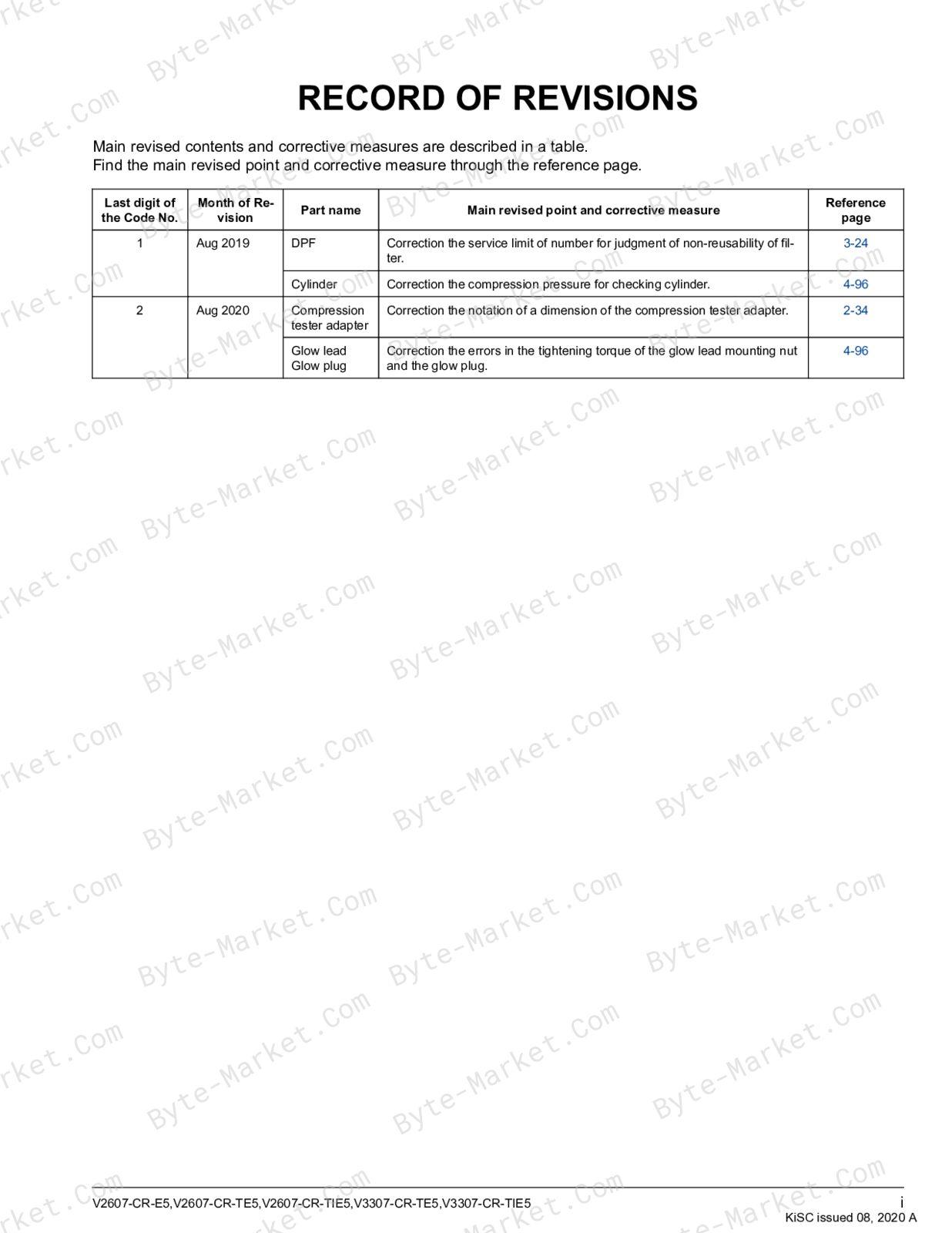
- August 2020 (A)
- Language
- English
- Page count
- 362
Product highlights
Electrical systems
The manual includes wiring diagrams, connector views, and pinouts.
Specifications and settings
The manual includes reference information for torque specifications, wear limits, clearances, capacities, and dimensions.
Special tools
A special-tools section is included.
Maintenance
The manual includes a maintenance schedule.
Applicability and key coverage
Named models: V2607-CR-E5, V2607-CR-TE5, V2607-CR-TIE5, V3307-CR-TE5, and V3307-CR-TIE5.
Manual contents
Use these source headings to locate the task or system you need in the PDF.
- 1. SAFETY — p. 19
- SAFETY FIRST — p. 20
- 1. Working precautions — p. 20
- 2. Preparing for emergencies — p. 20
- 3. Working cautions — p. 21
- 4. Starting machine safely — p. 22
- 5. Preventing fires — p. 22
- 6. Preventing acid burns — p. 23
- 7. Avoiding high pressure fluid — p. 23
- 8. Avoiding hot exhaust — p. 23
- 9. Cleaning exhaust filter — p. 23
- SAFETY FIRST — p. 20
- 2. GENERAL — p. 26
- GENERAL WORKING PRECAUTIONS — p. 27
- 1. Tightening bolts and nuts — p. 27
- 2. Applying thread-locking fluid — p. 27
- 3. Installing circlips — p. 27
- 4. Handling liquid gasket — p. 28
- 5. Replacing O-rings — p. 28
- 6. Replacing oil seals — p. 28
- 7. Handling the battery — p. 29
- 8. Handling wire harness — p. 29
- 9. Handling fuses — p. 30
- 10. Handling connectors — p. 31
- 11. Wiring color — p. 32
- 12. Dispose fluids correctly — p. 32
- ENGINE IDENTIFICATION — p. 33
- 1. Engine model name and engine serial number — p. 33
- 2. E5B engine — p. 34
- 3. Cylinder number — p. 35
- MUFFLER FULL ASSEMBLY IDENTIFICATION — p. 37
- 1. Part number and serial number (DPF) — p. 37
- INFORMATION — p. 39
- 1. Specifications — p. 39
- 1.1 Specification for V2607-CR-E5, V2607-CR-TE5, V2607-CR-TIE5 — p. 39
- 1.2 Specification for V3307-CR-TE5, V3307-CR-TIE5 — p. 40
- 2. Performance curves — p. 41
- 2.1 Performance curve for V2607-CR-E5 — p. 41
- 2.2 Performance curve for V2607-CR-TE5 — p. 42
- 2.3 Performance curve for V2607-CR-TIE5 — p. 43
- 2.4 Performance curve for V3307-CR-TE5 — p. 44
- 2.5 Performance curve for V3307-CR-TIE5 — p. 45
- 3. Dimensions — p. 46
- 3.1 Dimension for V2607-CR-E5 — p. 46
- 3.2 Dimension for V2607-CR-TE5, V2607-CR-TIE5 — p. 47
- 3.3 Dimension for V3307-CR-TE5, V3307-CR-TIE5 — p. 48
- 4. Wiring diagram — p. 49
- 4.1 Engine intermediate harness (Engine side harness) — p. 49
- 4.2 Injector intermediate harness (Engine side harness) — p. 51
- 4.3 Engine ECU intermediate harness (OEM side harness) — p. 52
- 4.4 System wiring diagram — p. 57
- 1. Specifications — p. 39
- SPECIAL TOOLS — p. 59
- 1. Diesel engine compression tester — p. 59
- 2. Oil pressure tester — p. 59
- 3. Compression tester adapter — p. 60
- 4. Small end bushing replacing tool — p. 62
- 5. Idle gear bushing replacing tool — p. 63
- 6. Valve guide replacing tool — p. 63
- 7. Front cover oil seal press fit tool — p. 64
- 8. Flywheel housing oil seal replacing tool — p. 65
- 9. Valve bridge shaft replacing tool — p. 67
- 10. Camshaft cover replacing tool for V3307-CR-TE5, V3307-CR-TIE5 — p. 70
- 11. Crankshaft sleeve press fit tool — p. 71
- 12. Crankcase 1 and 2 aligning tool — p. 73
- 13. Guide pin for suction control valve (SCV) — p. 75
- 14. Flywheel housing guide — p. 76
- 15. Camshaft position sensor bushing replacing tool — p. 79
- 16. Flywheel stopper — p. 79
- 17. Rotation sensor signal interface unit — p. 81
- GENERAL WORKING PRECAUTIONS — p. 27
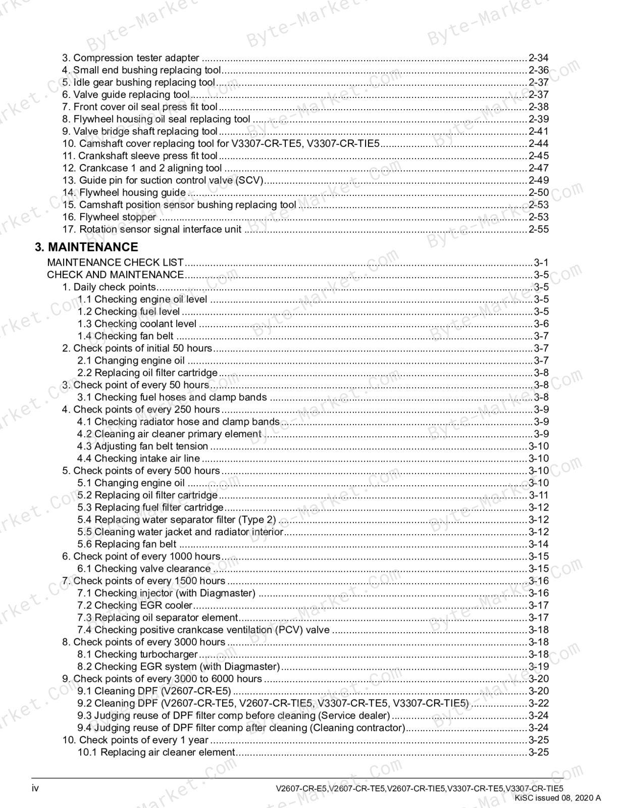
- 3. MAINTENANCE — p. 83
- MAINTENANCE CHECK LIST — p. 84
- CHECK AND MAINTENANCE — p. 88
- 1. Daily check points — p. 88
- 1.1 Checking engine oil level — p. 88
- 1.2 Checking fuel level — p. 88
- 1.3 Checking coolant level — p. 89
- 1.4 Checking fan belt — p. 90
- 2. Check points of initial 50 hours — p. 90
- 2.1 Changing engine oil — p. 90
- 2.2 Replacing oil filter cartridge — p. 91
- 3. Check point of every 50 hours — p. 91
- 3.1 Checking fuel hoses and clamp bands — p. 91
- 4. Check points of every 250 hours — p. 92
- 4.1 Checking radiator hose and clamp bands — p. 92
- 4.2 Cleaning air cleaner primary element — p. 92
- 4.3 Adjusting fan belt tension — p. 93
- 4.4 Checking intake air line — p. 93
- 5. Check points of every 500 hours — p. 93
- 5.1 Changing engine oil — p. 93
- 5.2 Replacing oil filter cartridge — p. 94
- 5.3 Replacing fuel filter cartridge — p. 95
- 5.4 Replacing water separator filter (Type 2) — p. 95
- 5.5 Cleaning water jacket and radiator interior — p. 95
- 5.6 Replacing fan belt — p. 97
- 6. Check point of every 1000 hours — p. 98
- 6.1 Checking valve clearance — p. 98
- 7. Check points of every 1500 hours — p. 99
- 7.1 Checking injector (with Diagmaster) — p. 99
- 7.2 Checking EGR cooler — p. 100
- 7.3 Replacing oil separator element — p. 100
- 7.4 Checking positive crankcase ventilation (PCV) valve — p. 101
- 8. Check points of every 3000 hours — p. 101
- 8.1 Checking turbocharger — p. 101
- 8.2 Checking EGR system (with Diagmaster) — p. 102
- 9. Check points of every 3000 to 6000 hours — p. 103
- 9.1 Cleaning DPF (V2607-CR-E5) — p. 103
- 9.2 Cleaning DPF (V2607-CR-TE5, V2607-CR-TIE5, V3307-CR-TE5, V3307-CR-TIE5) — p. 105
- 9.3 Judging reuse of DPF filter comp before cleaning (Service dealer) — p. 107
- 9.4 Judging reuse of DPF filter comp after cleaning (Cleaning contractor) — p. 107
- 10. Check points of every 1 year — p. 108
- 10.1 Replacing air cleaner element — p. 108
- 10.2 Checking DPF differential pressure pipes and hoses — p. 109
- 10.3 Checking EGR piping — p. 110
- 10.4 Checking intake air line — p. 110
- 10.5 Checking exhaust manifold — p. 110
- 10.6 Replacing water separator filter (Type 2) — p. 110
- 11. Check points of every 2 years — p. 111
- 11.1 Replacing fan belt — p. 111
- 11.2 Replacing oil separator rubber hose — p. 111
- 11.3 Replacing rubber hose of differential pressure sensor — p. 111
- 11.4 Replacing intake hose (after air flow sensor) and intercooler hose — p. 112
- 11.5 Replacing pressure detection hose of boost pressure sensor — p. 112
- 11.6 Replacing EGR cooler hose — p. 112
- 11.7 Replacing water hose — p. 112
- 11.8 Replacing lubricant hose — p. 112
- 11.9 Changing radiator coolant — p. 112
- 11.10 Replacing radiator hose and clamp bands — p. 114
- 11.11 Replacing fuel hose and clamps — p. 115
- 11.12 Replacing intake air line — p. 115
- 1. Daily check points — p. 88
- 4. ENGINE — p. 116
- MECHANISM — p. 117
- 1. General (Introduction) — p. 117
- 1.1 Feature of combustion (E-CDIS) — p. 117
- 1.2 Structure of combustion (Center direct injection system (E-CDIS)) — p. 117
- 1.3 Flow of combustion (E-CDIS) — p. 117
- 1.4 Control of combustion (E-CDIS) — p. 118
- 2. Engine body — p. 119
- 2.1 Structure of engine body — p. 119
- 2.2 Feature of engine body — p. 120
- 2.3 Crankcase — p. 120
- 2.3.1 Outline of crankcase — p. 120
- 2.3.2 Structure of crankcase — p. 120
- 2.3.3 Function of crankcase — p. 120
- 2.3.4 Specification of crankcase — p. 120
- 2.4 Cylinder head — p. 121
- 2.4.1 Outline of cylinder head — p. 121
- 2.4.2 Structure of cylinder head — p. 121
- 2.4.3 Function of cylinder head — p. 121
- 2.5 Cylinder head cover — p. 121
- 2.5.1 Outline of cylinder head cover — p. 121
- 2.5.2 Structure of cylinder head cover — p. 121
- 2.5.3 Function of cylinder head cover — p. 121
- 2.6 Breather — p. 122
- 2.6.1 Outline of breather — p. 122
- 2.6.2 Structure of breather — p. 122
- 2.6.3 Function of breather — p. 122
- 2.7 Oil separator — p. 122
- 2.7.1 Outline of oil separator — p. 122
- 2.7.2 Structure of oil separator — p. 122
- 2.7.3 Function of oil separator — p. 122
- 2.8 Piston — p. 122
- 2.8.1 Outline of piston — p. 122
- 2.8.2 Structure of piston — p. 122
- 2.8.3 Function of piston — p. 123
- 2.8.4 Specification of piston — p. 123
- 2.9 Piston ring — p. 124
- 2.9.1 Outline of piston ring — p. 124
- 2.9.2 Structure of piston ring — p. 124
- 2.9.3 Function of piston ring — p. 124
- 2.9.4 Specification of piston ring — p. 124
- 2.10 Connecting rod — p. 124
- 2.10.1 Outline of connecting rod — p. 124
- 2.10.2 Structure of connecting rod — p. 124
- 2.10.3 Function of connecting rod — p. 125
- 2.11 Crankshaft — p. 125
- 2.11.1 Outline of crankshaft — p. 125
- 2.11.2 Structure of crankshaft — p. 125
- 2.11.3 Function of crankshaft — p. 125
- 2.11.4 Specification of crankshaft — p. 125
- 2.12 Main bearing case — p. 125
- 2.12.1 Outline of main bearing case — p. 125
- 2.12.2 Structure of main bearing case — p. 125
- 2.12.3 Function of main bearing case — p. 125
- 2.13 Flywheel — p. 126
- 2.13.1 Outline of flywheel — p. 126
- 2.13.2 Structure of flywheel — p. 126
- 2.13.3 Function of flywheel — p. 126
- 2.13.4 Specification of flywheel — p. 126
- 2.14 Rocker arm assembly — p. 126
- 2.14.1 Outline of rocker arm assembly — p. 126
- 2.14.2 Structure of rocker arm assembly — p. 126
- 2.14.3 Function of rocker arm assembly — p. 126
- 2.15 Camshaft — p. 127
- 2.15.1 Outline of camshaft — p. 127
- 2.15.2 Structure of camshaft — p. 127
- 2.15.3 Function of camshaft — p. 127
- 2.15.4 Specification of camshaft — p. 127
- 2.16 Valve — p. 127
- 2.16.1 Outline of valve — p. 127
- 2.16.2 Structure of valve — p. 127
- 2.16.3 Function of valve — p. 127
- 2.16.4 Specification of valve — p. 128
- 2.17 Tappet — p. 128
- 2.17.1 Outline of tappet — p. 128
- 2.17.2 Structure of tappet — p. 128
- 2.17.3 Function of tappet — p. 128
- 2.18 Push rod — p. 128
- 2.18.1 Outline of push rod — p. 128
- 2.18.2 Structure of push rod — p. 128
- 2.18.3 Function of push rod — p. 129
- 2.19 Timing gears — p. 129
- 2.19.1 Outline of timing gears — p. 129
- 2.19.2 Structure of timing gears — p. 129
- 2.19.3 Function of timing gears — p. 129
- 3. Fuel system — p. 130
- 3.1 Structure of common rail system (CRS) engine — p. 130
- 3.2 Feature of common rail system (CRS) engine — p. 131
- 3.3 Flow of common rail system (CRS) engine — p. 132
- 3.4 Control of common rail system (CRS) engine — p. 134
- 3.5 Fuel tank — p. 134
- 3.5.1 Outline of fuel tank — p. 134
- 3.5.2 Structure of fuel tank — p. 134
- 3.5.3 Function of fuel tank — p. 134
- 3.5.4 Specification of fuel tank — p. 134
- 3.6 Water separator — p. 134
- 3.6.1 Outline of water separator — p. 134
- 3.6.2 Structure of water separator (Type2) — p. 134
- 3.6.3 Function of water separator — p. 134
- 3.6.4 Specification of water separator (Type2) — p. 134
- 3.7 Electromagnetic fuel feed pump — p. 135
- 3.7.1 Outline of electromagnetic fuel feed pump — p. 135
- 3.7.2 Structure of electromagnetic fuel feed pump — p. 135
- 3.7.3 Function of electromagnetic fuel feed pump — p. 135
- 3.7.4 Specification of electromagnetic fuel feed pump — p. 135
- 3.8 Fuel filter — p. 135
- 3.8.1 Outline of fuel filter — p. 135
- 3.8.2 Structure of fuel filter — p. 135
- 3.8.3 Function of fuel filter — p. 135
- 3.8.4 Specification of fuel filter — p. 135
- 3.9 Supply pump — p. 136
- 3.9.1 Outline of supply pump — p. 136
- 3.9.2 Structure of supply pump — p. 136
- 3.9.3 Function of supply pump — p. 137
- 3.9.4 Specification of supply pump — p. 137
- 3.10 Injection pipe — p. 137
- 3.10.1 Outline of injection pipe — p. 137
- 3.10.2 Structure of injection pipe — p. 137
- 3.10.3 Function of injection pipe — p. 137
- 3.10.4 Specification of injection pipe — p. 137
- 3.11 Rail assembly — p. 138
- 3.11.1 Outline of rail assembly — p. 138
- 3.11.2 Structure of rail assembly — p. 138
- 3.11.3 Function of rail assembly — p. 138
- 3.11.4 Specification of rail assembly — p. 138
- 3.12 Injector — p. 139
- 3.12.1 Outline of injector — p. 139
- 3.12.2 Structure of injector — p. 139
- 3.12.3 Function of injector — p. 140
- 3.12.4 Specification of injector — p. 142
- 3.13 Overflow pipe — p. 142
- 3.13.1 Outline of overflow pipe — p. 142
- 3.13.2 Structure of overflow pipe — p. 142
- 3.13.3 Function of overflow pipe — p. 142
- 3.14 Check valve — p. 142
- 3.14.1 Outline of check valve — p. 142
- 3.14.2 Structure of check valve — p. 142
- 3.14.3 Function of check valve — p. 142
- 3.14.4 Specification of check valve — p. 143
- 3.15 Fuel cooler — p. 143
- 3.15.1 Outline of fuel cooler — p. 143
- 3.15.2 Structure of fuel cooler — p. 143
- 3.15.3 Function of fuel cooler — p. 143
- 3.16 Engine ECU — p. 143
- 3.16.1 Outline of engine ECU — p. 143
- 3.16.2 Structure of engine ECU — p. 143
- 3.16.3 Function of engine ECU — p. 143
- 3.16.4 Specification of engine ECU — p. 144
- 3.17 Crankshaft position sensor — p. 144
- 3.17.1 Outline of crankshaft position sensor — p. 144
- 3.17.2 Structure of crankshaft position sensor — p. 144
- 3.17.3 Function of crankshaft position sensor — p. 144
- 3.17.4 Specification of crankshaft position sensor — p. 144
- 3.18 Camshaft position sensor — p. 145
- 3.18.1 Outline of camshaft position sensor — p. 145
- 3.18.2 Structure of camshaft position sensor — p. 145
- 3.18.3 Function of camshaft position sensor — p. 145
- 3.18.4 Specification of camshaft position sensor — p. 145
- 3.19 Intake air temperature sensor — p. 146
- 3.19.1 Outline of intake air temperature sensor — p. 146
- 3.19.2 Structure of intake air temperature sensor — p. 146
- 3.19.3 Function of intake air temperature sensor — p. 146
- 3.19.4 Specification of intake air temperature sensor — p. 146
- 3.20 Coolant temperature sensor — p. 146
- 3.20.1 Outline of coolant temperature sensor — p. 146
- 3.20.2 Structure of coolant temperature sensor — p. 146
- 3.20.3 Function of coolant temperature sensor — p. 147
- 3.20.4 Specification of coolant temperature sensor — p. 147
- 3.21 Boost pressure sensor — p. 147
- 3.21.1 Outline of boost pressure sensor — p. 147
- 3.21.2 Structure of boost pressure sensor — p. 147
- 3.21.3 Function of boost pressure sensor — p. 148
- 3.21.4 Specification of boost pressure sensor — p. 148
- 3.22 Atmosphere pressure sensor — p. 148
- 3.22.1 Outline of atmosphere pressure sensor — p. 148
- 3.22.2 Structure of atmosphere pressure sensor — p. 148
- 3.22.3 Function of atmosphere pressure sensor — p. 148
- 4. Intake and exhaust system — p. 149
- 4.1 Structure of intake and exhaust system — p. 149
- 4.2 Feature of intake and exhaust system — p. 150
- 4.3 Flow of intake and exhaust system — p. 151
- 4.4 Control of intake and exhaust system — p. 152
- 4.5 Pre-cleaner — p. 152
- 4.5.1 Outline of pre-cleaner — p. 152
- 4.5.2 Structure of pre-cleaner — p. 152
- 4.5.3 Function of pre-cleaner — p. 153
- 4.5.4 Specification of pre-cleaner — p. 153
- 4.6 Air cleaner — p. 153
- 4.6.1 Outline of air cleaner — p. 153
- 4.6.2 Structure of air cleaner — p. 153
- 4.6.3 Function of air cleaner — p. 153
- 4.6.4 Specification of air cleaner — p. 153
- 4.7 Turbocharger — p. 153
- 4.7.1 Outline of turbocharger — p. 153
- 4.7.2 Structure of turbocharger — p. 153
- 4.7.3 Function of turbocharger — p. 153
- 4.7.4 Specification of turbocharger — p. 154
- 4.8 Intercooler — p. 154
- 4.8.1 Outline of intercooler — p. 154
- 4.8.2 Structure of intercooler — p. 154
- 4.8.3 Function of intercooler — p. 154
- 4.8.4 Specification of intercooler — p. 154
- 4.9 Glow plug — p. 154
- 4.9.1 Outline of glow plug — p. 154
- 4.9.2 Structure of glow plug — p. 154
- 4.9.3 Function of glow plug — p. 154
- 4.9.4 Specification of glow plug — p. 154
- 4.10 Intake manifold — p. 155
- 4.10.1 Outline of intake manifold — p. 155
- 4.10.2 Structure of intake manifold — p. 155
- 4.10.3 Function of intake manifold — p. 155
- 4.11 Exhaust manifold — p. 155
- 4.11.1 Outline of exhaust manifold — p. 155
- 4.11.2 Structure of exhaust manifold — p. 155
- 4.11.3 Function of exhaust manifold — p. 155
- 5. Exhaust gas recirculation (EGR) system — p. 156
- 5.1 Structure of EGR system — p. 156
- 5.2 Feature of EGR system — p. 157
- 5.3 Flow of EGR system — p. 158
- 5.4 Control of EGR system — p. 159
- 5.5 EGR cooler — p. 159
- 5.5.1 Outline of EGR cooler — p. 159
- 5.5.2 Structure of EGR cooler — p. 159
- 5.5.3 Function of EGR cooler — p. 159
- 5.5.4 Specification of EGR cooler — p. 159
- 5.6 EGR valve — p. 159
- 5.6.1 Outline of EGR valve — p. 159
- 5.6.2 Structure of EGR valve — p. 160
- 5.6.3 Function of EGR valve — p. 162
- 5.6.4 Specification of EGR valve — p. 162
- 5.7 Reed valve — p. 162
- 5.7.1 Outline of reed valve — p. 162
- 5.7.2 Structure of reed valve — p. 162
- 5.7.3 Function of reed valve — p. 162
- 6. Lubricating system — p. 163
- 6.1 Structure of lubricating system — p. 163
- 6.2 Feature of lubricating system — p. 164
- 6.3 Flow of lubricating system — p. 165
- 6.4 Oil pan — p. 167
- 6.4.1 Outline of oil pan — p. 167
- 6.4.2 Structure of oil pan — p. 167
- 6.4.3 Function of oil pan — p. 167
- 6.4.4 Specification of oil pan — p. 167
- 6.5 Oil strainer — p. 167
- 6.5.1 Outline of oil strainer — p. 167
- 6.5.2 Structure of oil strainer — p. 167
- 6.5.3 Function of oil strainer — p. 167
- 6.5.4 Specification of oil strainer — p. 167
- 6.6 Oil pump — p. 168
- 6.6.1 Outline of oil pump — p. 168
- 6.6.2 Structure of oil pump — p. 168
- 6.6.3 Function of oil pump — p. 168
- 6.6.4 Specification of oil pump — p. 168
- 6.7 Relief valve — p. 168
- 6.7.1 Outline of relief valve — p. 168
- 6.7.2 Structure of relief valve — p. 168
- 6.7.3 Function of relief valve — p. 169
- 6.7.4 Specification of relief valve — p. 169
- 6.8 Oil filter — p. 169
- 6.8.1 Outline of oil filter — p. 169
- 6.8.2 Structure of oil filter — p. 169
- 6.8.3 Function of oil filter — p. 169
- 6.8.4 Specification of oil filter — p. 169
- 6.9 Oil cooler — p. 170
- 6.9.1 Outline of oil cooler — p. 170
- 6.9.2 Structure of oil cooler — p. 170
- 6.9.3 Function of oil cooler — p. 170
- 6.9.4 Specification of oil cooler — p. 170
- 6.10 Oil pressure switch — p. 170
- 6.10.1 Outline of oil pressure switch — p. 170
- 6.10.2 Structure of oil pressure switch — p. 170
- 6.10.3 Function of oil pressure switch — p. 171
- 6.10.4 Specification of oil pressure switch — p. 171
- 7. Cooling system — p. 172
- 7.1 Structure of cooling system — p. 172
- 7.2 Feature of cooling system — p. 173
- 7.3 Flow of cooling system (Bottom by-pass system) — p. 173
- 7.4 Control of cooling system (Bottom by-pass system) — p. 173
- 7.5 Water pump — p. 174
- 7.5.1 Outline of water pump — p. 174
- 7.5.2 Structure of water pump — p. 174
- 7.5.3 Function of water pump — p. 174
- 7.6 Thermostat — p. 174
- 7.6.1 Outline of thermostat — p. 174
- 7.6.2 Structure of thermostat — p. 174
- 7.6.3 Function of thermostat — p. 175
- 7.6.4 Specification of thermostat — p. 175
- 7.7 Radiator — p. 175
- 7.7.1 Outline of radiator — p. 175
- 7.7.2 Structure of radiator — p. 176
- 7.7.3 Function of radiator — p. 176
- 7.7.4 Specification of radiator — p. 176
- 7.8 Radiator cap — p. 176
- 7.8.1 Outline of radiator cap — p. 176
- 7.8.2 Structure of radiator cap — p. 176
- 7.8.3 Function of radiator cap — p. 176
- 7.8.4 Specification of radiator cap — p. 177
- 7.9 Cooling fan — p. 177
- 7.9.1 Outline of cooling fan — p. 177
- 7.9.2 Structure of cooling fan — p. 177
- 7.9.3 Function of cooling fan — p. 177
- 7.9.4 Specification of cooling fan — p. 177
- 7.10 Reserve tank — p. 178
- 7.10.1 Outline of reserve tank — p. 178
- 7.10.2 Structure of reserve tank — p. 178
- 7.10.3 Function of reserve tank — p. 178
- 7.11 Fan belt — p. 178
- 7.11.1 Outline of fan belt — p. 178
- 7.11.2 Structure of fan belt — p. 178
- 7.11.3 Function of fan belt — p. 178
- 8. Electrical system — p. 179
- 8.1 Structure of electrical system — p. 179
- 8.2 Feature of electrical system — p. 180
- 8.3 Flow of electrical system — p. 181
- 8.4 Control of electrical system — p. 183
- 8.5 Battery — p. 183
- 8.5.1 Outline of battery — p. 183
- 8.5.2 Structure of battery — p. 183
- 8.5.3 Function of battery — p. 183
- 8.5.4 Specification of battery — p. 183
- 8.6 Key switch — p. 183
- 8.6.1 Outline of key switch — p. 183
- 8.6.2 Structure of key switch — p. 183
- 8.6.3 Function of key switch — p. 184
- 8.6.4 Specification of key switch — p. 184
- 8.7 Starter (Planetary gear reduction type) — p. 184
- 8.7.1 Outline of starter (planetary gear reduction type) — p. 184
- 8.7.2 Structure of starter (planetary gear reduction type) — p. 184
- 8.7.3 Function of starter (planetary gear reduction type) — p. 184
- 8.7.4 Specification of starter (Planetary gear reduction type) — p. 185
- 8.8 Alternator — p. 185
- 8.8.1 Outline of alternator — p. 185
- 8.8.2 Structure of alternator — p. 185
- 8.8.3 Function of alternator — p. 185
- 8.8.4 Specification of alternator — p. 186
- 9. Aftertreatment system — p. 186
- 9.1 Structure of diesel particulate filter (DPF) system — p. 186
- 9.2 Feature of diesel particulate filter (DPF) system — p. 186
- 9.3 Flow of diesel particulate filter (DPF) system — p. 187
- 9.4 Control of diesel particulate filter (DPF) system — p. 188
- 9.5 Diesel oxidation catalyst (DOC) — p. 190
- 9.5.1 Outline of diesel oxidation catalyst (DOC) — p. 190
- 9.5.2 Structure of diesel oxidation catalyst (DOC) — p. 190
- 9.5.3 Function of diesel oxidation catalyst (DOC) — p. 190
- 9.6 Diesel particulate filter (DPF) — p. 191
- 9.6.1 Outline of diesel particulate filter (DPF) — p. 191
- 9.6.2 Structure of diesel particulate filter (DPF) — p. 191
- 9.6.3 Function of diesel particulate filter (DPF) — p. 191
- 9.7 Air flow sensor — p. 192
- 9.7.1 Outline of air flow sensor — p. 192
- 9.7.2 Structure of air flow sensor — p. 192
- 9.7.3 Function of air flow sensor — p. 192
- 9.7.4 Specification of air flow sensor — p. 192
- 9.8 Exhaust gas temperature sensor — p. 193
- 9.8.1 Outline of exhaust gas temperature sensor — p. 193
- 9.8.2 Structure of exhaust gas temperature sensor — p. 193
- 9.8.3 Function of exhaust gas temperature sensor — p. 194
- 9.8.4 Specification of exhaust gas temperature sensor — p. 194
- 9.9 Differential pressure sensor — p. 194
- 9.9.1 Outline of differential pressure sensor — p. 194
- 9.9.2 Structure of differential pressure sensor — p. 194
- 9.9.3 Function of differential pressure sensor — p. 195
- 9.9.4 Specification of differential pressure sensor — p. 195
- 9.10 Intake throttle valve — p. 195
- 9.10.1 Outline of intake throttle valve — p. 195
- 9.10.2 Structure of intake throttle valve — p. 195
- 9.10.3 Function of intake throttle valve — p. 196
- 9.10.4 Specification of intake throttle valve — p. 196
- 1. General (Introduction) — p. 117
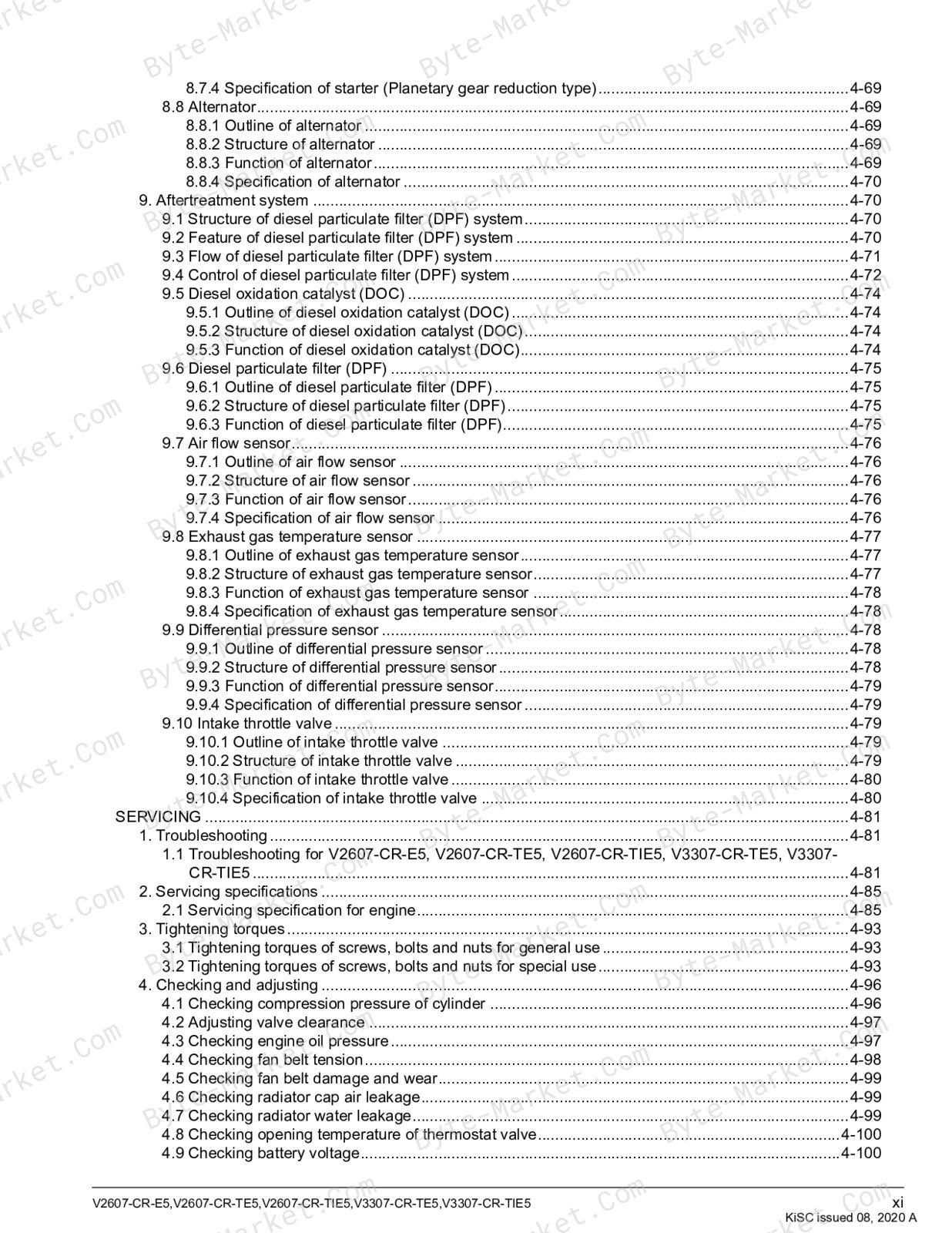
- SERVICING — p. 197
- 1. Troubleshooting — p. 197
- 1.1 Troubleshooting for V2607-CR-E5, V2607-CR-TE5, V2607-CR-TIE5, V3307-CR-TE5, V3307-CR-TIE5 — p. 197
- 2. Servicing specifications — p. 201
- 2.1 Servicing specification for engine — p. 201
- 3. Tightening torques — p. 209
- 3.1 Tightening torques of screws, bolts and nuts for general use — p. 209
- 3.2 Tightening torques of screws, bolts and nuts for special use — p. 209
- 4. Checking and adjusting — p. 212
- 4.1 Checking compression pressure of cylinder — p. 212
- 4.2 Adjusting valve clearance — p. 213
- 4.3 Checking engine oil pressure — p. 213
- 4.4 Checking fan belt tension — p. 214
- 4.5 Checking fan belt damage and wear — p. 215
- 4.6 Checking radiator cap air leakage — p. 215
- 4.7 Checking radiator water leakage — p. 215
- 4.8 Checking opening temperature of thermostat valve — p. 216
- 4.9 Checking battery voltage — p. 216
- 4.10 Checking battery specific gravity — p. 217
- 4.11 Checking starter motor — p. 218
- 4.12 Checking magnetic switch of starter — p. 218
- 4.13 Checking magnetic switch continuity — p. 219
- 4.14 Checking alternator on unit — p. 219
- 4.15 Checking glow plug continuity — p. 220
- 4.16 Checking exhaust gas leakage of turbocharger turbine side — p. 221
- 4.17 Checking air leakage of turbocharger compressor side — p. 221
- 4.18 Checking radial clearance of turbocharger — p. 221
- 4.19 Checking injector — p. 221
- 4.20 Checking suction control valve (SCV) — p. 222
- 4.21 Checking boost pressure sensor — p. 222
- 4.22 Checking intake air temperature sensor — p. 223
- 4.23 Checking crankshaft position sensor — p. 224
- 4.24 Checking camshaft position sensor — p. 224
- 4.25 Checking coolant temperature sensor — p. 224
- 4.26 Checking EGR system — p. 225
- 4.27 Checking air flow sensor — p. 225
- 4.28 Checking exhaust gas temperature sensor — p. 226
- 4.29 Checking fuel leakage of overflow pipe — p. 226
- 4.30 Selecting cylinder head gasket (V2607-CR-E5, V2607-CR-TE5, V2607-CR-TIE5) — p. 227
- 4.31 Selecting cylinder head gasket (V3307-CR-TE5, V3307-CR-TIE5) — p. 228
- 4.32 Measuring angular deviation between crankshaft T.D.C. and crank position sensor detected T.D.C — p. 229
- 4.33 Adjusting air gap between crankshaft position sensor and pulsar gear — p. 232
- 5. Disassembling — p. 233
- 5.1 Draining engine oil — p. 233
- 5.2 Draining coolant — p. 233
- 5.3 Removing CRS intermediate harness — p. 235
- 5.4 Removing external components — p. 238
- 5.5 Removing DPF muffler full assembly (V2607-CR-E5) — p. 239
- 5.6 Removing DPF muffler full assembly (V2607-CR-TE5, V3307-CR-TE5, V2607-CR-TIE5, V3307-CR-TIE5) — p. 240
- 5.7 Disassembling DPF muffler full assembly (V2607-CR-E5) — p. 241
- 5.8 Disassembling DPF muffler full assembly (V2607-CR-TE5, V3307-CR-TE5, V2607-CR-TIE5, V3307-CR-TIE5) — p. 241
- 5.9 Removing turbocharger assembly — p. 242
- 5.10 Removing EGR cooler — p. 242
- 5.11 Removing EGR valve — p. 242
- 5.12 Removing sensors — p. 243
- 5.13 Removing intake throttle valve — p. 244
- 5.14 Removing common rail — p. 244
- 5.15 Removing glow plug — p. 245
- 5.16 Removing cylinder head cover — p. 245
- 5.17 Removing injector — p. 245
- 5.18 Removing rocker arm assembly — p. 246
- 5.19 Removing injector oil seal and injection pipe oil seal — p. 247
- 5.20 Removing cylinder head — p. 247
- 5.21 Removing valve — p. 248
- 5.22 Removing thermostat assembly — p. 248
- 5.23 Removing suction control valve (SCV) — p. 248
- 5.24 Removing fuel temperature sensor — p. 249
- 5.25 Removing supply pump — p. 249
- 5.26 Removing supply pump gear and crank pulsar gear — p. 250
- 5.27 Removing fan drive pulley — p. 251
- 5.28 Removing water pump — p. 251
- 5.29 Removing oil cooler — p. 252
- 5.30 Removing front cover — p. 252
- 5.31 Removing relief valve — p. 252
- 5.32 Removing flywheel — p. 252
- 5.33 Removing flywheel housing (V2607-CR-E5, V2607-CR-TE5, V2607-CR-TIE5) — p. 253
- 5.34 Removing flywheel housing (V3307-CR-TE5, V3307-CR-TIE5) — p. 253
- 5.35 Removing idle gear — p. 253
- 5.36 Removing camshaft with cam gear — p. 254
- 5.37 Removing oil pan and oil strainer — p. 254
- 5.38 Removing tappet — p. 255
- 5.39 Removing piston — p. 255
- 5.40 Removing piston ring — p. 256
- 5.41 Disassembling piston assembly — p. 256
- 5.42 Removing crankcase 2 — p. 257
- 5.42.1 Installing tappet — p. 257
- 5.43 Removing crankshaft — p. 258
- 5.44 Disassembling starter — p. 258
- 5.45 Disassembling alternator — p. 258
- 6. Assembling — p. 259
- 6.1 Assembling alternator — p. 259
- 6.2 Assembling starter — p. 261
- 6.3 Installing crankshaft — p. 261
- 6.4 Installing crankcase 2 — p. 262
- 6.5 Assembling piston assembly — p. 264
- 6.6 Installing piston ring — p. 264
- 6.7 Installing piston — p. 265
- 6.8 Installing tappet — p. 267
- 6.9 Installing oil strainer and oil pan — p. 267
- 6.10 Installing camshaft with cam gear — p. 268
- 6.11 Installing idle gear — p. 269
- 6.12 Installing supply pump gear and crank pulsar gear — p. 269
- 6.13 Installing supply pump — p. 270
- 6.14 Installing flywheel housing (V2607-CR-E5, V2607-CR-TE5, V2607-CR-TIE5) — p. 271
- 6.15 Installing flywheel housing (V3307-CR-TE5, V3307-CR-TIE5) — p. 272
- 6.16 Installing flywheel — p. 273
- 6.17 Installing relief valve — p. 274
- 6.18 Installing front cover — p. 275
- 6.19 Installing oil cooler — p. 275
- 6.20 Installing water pump — p. 276
- 6.21 Installing fan drive pulley — p. 276
- 6.22 Installing fuel temperature sensor — p. 276
- 6.23 Installing suction control valve (SCV) — p. 277
- 6.24 Installing thermostat assembly — p. 278
- 6.25 Installing valve — p. 279
- 6.26 Installing cylinder head — p. 279
- 6.27 Installing injector oil seal and injection pipe oil seal — p. 281
- 6.28 Installing rocker arm assembly — p. 281
- 6.29 Installing injector — p. 282
- 6.30 Installing cylinder head cover — p. 284
- 6.31 Installing glow plug — p. 284
- 6.32 Installing common rail — p. 285
- 6.33 Installing intake throttle valve — p. 286
- 6.34 Installing sensors — p. 286
- 6.35 Installing EGR valve — p. 287
- 6.36 Installing EGR cooler — p. 287
- 6.37 Installing turbocharger assembly — p. 288
- 6.38 Assembling DPF muffler full assembly (V2607-CR-TE5, V3307-CR-TE5, V2607-CR-TIE5, V3307-CR-TIE5) — p. 288
- 6.39 Assembling DPF muffler full assembly (V2607-CR-E5) — p. 289
- 6.40 Installing DPF muffler full assembly (V2607-CR-TE5, V3307-CR-TE5, V2607-CR-TIE5, V3307-CR-TIE5) — p. 290
- 6.41 Installing DPF muffler full assembly (V2607-CR-E5) — p. 291
- 6.42 Installing external components — p. 293
- 6.43 Installing CRS intermediate harness — p. 294
- 6.44 Filling coolant — p. 297
- 6.45 Filling engine oil — p. 297
- 7. Servicing — p. 298
- 7.1 Checking cylinder head top clearance — p. 298
- 7.2 Checking cylinder head surface flatness — p. 298
- 7.3 Checking cylinder head flaw — p. 299
- 7.4 Checking valve recessing — p. 299
- 7.5 Adjusting valve lapping — p. 300
- 7.6 Checking clearance between valve stem and valve guide — p. 300
- 7.7 Replacing valve guide — p. 301
- 7.8 Adjusting valve angle — p. 302
- 7.9 Adjusting valve seat — p. 302
- 7.10 Checking free length of valve spring — p. 303
- 7.11 Checking tilt of valve spring — p. 303
- 7.12 Checking set load of valve spring — p. 304
- 7.13 Checking oil clearance between rocker arm and rocker arm shaft — p. 304
- 7.14 Checking oil clearance between valve bridge shaft and valve bridge arm — p. 305
- 7.15 Replacing valve bridge shaft (V2607-CR-E5, V2607-CR-TE5, V2607-CR-TIE5) — p. 306
- 7.16 Replacing valve bridge shaft (V3307-CR-TE5, V3307-CR-TIE5) — p. 307
- 7.17 Checking push rod alignment — p. 307
- 7.18 Checking oil clearance between tappet and tappet guide bore — p. 307
- 7.19 Checking timing gear backlash — p. 308
- 7.20 Checking side clearance of idle gear — p. 309
- 7.21 Checking oil clearance between idle gear shaft and idle gear bushing — p. 309
- 7.22 Replacing idle gear bushing — p. 310
- 7.23 Checking side clearance of camshaft — p. 310
- 7.24 Checking camshaft alignment — p. 311
- 7.25 Checking cam height — p. 311
- 7.26 Checking oil clearance between camshaft journal and crankcase bore — p. 312
- 7.27 Replacing camshaft cover — p. 312
- 7.28 Checking piston pin bore I.D — p. 312
- 7.29 Checking oil clearance between piston pin and small end bushing — p. 313
- 7.30 Replacing small end bushing (V2607-CR-E5, V2607-CR-TE5, V2607-CR-TIE5) — p. 314
- 7.31 Replacing small end bushing (V3307-CR-TE5, V3307-CR-TIE5) — p. 315
- 7.32 Checking connecting rod alignment — p. 316
- 7.33 Checking piston ring gap — p. 316
- 7.34 Checking clearance between piston ring and ring groove — p. 317
- 7.35 Checking side clearance of crankshaft — p. 317
- 7.36 Checking crankshaft alignment — p. 318
- 7.37 Checking oil clearance between crankpin and crankpin bearing — p. 319
- 7.38 Checking oil clearance between crankshaft journal and crankshaft bearing — p. 320
- 7.39 Replacing crankshaft sleeve — p. 322
- 7.40 Replacing flywheel housing oil seal — p. 323
- 7.41 Replacing front cover oil seal — p. 323
- 7.42 Replacing camshaft position sensor bushing — p. 324
- 7.43 Checking cylinder wear — p. 324
- 7.44 Adjusting cylinder correction (over size) — p. 325
- 7.45 Checking clearance between inner rotor and outer rotor — p. 326
- 7.46 Checking clearance between outer rotor and pump body — p. 326
- 7.47 Checking clearance between rotor and cover — p. 327
- 7.48 Checking free length of relief valve spring — p. 327
- 7.49 Checking overrunning clutch of starter — p. 328
- 7.50 Checking commutator and mica of starter — p. 328
- 7.51 Checking brush wear of starter — p. 329
- 7.52 Checking brush holder of starter — p. 329
- 7.53 Checking armature coil of starter — p. 329
- 7.54 Checking field coil of starter — p. 330
- 7.55 Checking bearing of alternator — p. 331
- 7.56 Checking stator of alternator — p. 331
- 7.57 Checking rotor of alternator — p. 331
- 7.58 Checking slip ring of alternator — p. 331
- 7.59 Checking brush wear of alternator — p. 332
- 7.60 Replacing suction control valve (SCV) — p. 332
- 7.61 Replacing fuel temperature sensor — p. 335
- 7.62 Replacing supply pump — p. 337
- 7.63 Replacing injector — p. 340
- 7.64 Replacing engine ECU — p. 342
- 7.65 Replacing DPF — p. 345
- 1. Troubleshooting — p. 197
- MECHANISM — p. 117
Capabilities
The source outline separates mechanism explanations from servicing instructions for 4. Engine. Use these indexed headings to locate the applicable system in the source PDF, then confirm model-specific notes, specifications, illustrations, and operating conditions at the relevant page before carrying out service work.
Keep the source's safety sequence, prerequisite steps, labels, units, configuration notes, and footnotes with the selected task; do not apply an isolated value outside the conditions stated in the manual.
Technical reference
Reference tables include torque settings, wear limits, fluid and system capacities, and dimensions for service checks, adjustment work, and specification lookup. Use the values and conditions in the PDF for the applicable model and procedure.
- Service limits and settings: torque settings and wear limits.
- Fluid reference: fluid and system capacities.
- Machine specifications: dimensions.
Delivery
This manual is supplied as a digital PDF file and is available for instant download after purchase. No physical media is shipped.
References
Kubota Workshop Manual for Engine, document code 9Y311-00072, PDF edition.


No questions found.