
About this manual
New Holland E215B / E245B Service Manual 84392396A is an English-language service manual for crawler excavators.
The manual covers safety precautions, operational principles, performance tests, troubleshooting and repair instructions. It is written for experienced technicians maintaining and repairing the machine.
Manual details
- Models
- E215B, E245B
- Publisher
- NEW HOLLAND KOBELCO CONSTRUCTION MACHINERY S.p.A.
- Manual type
- Service Manual
- Document number
- 84392396A
- Machine category
- Crawler Excavator
- Emission tier
- Tier III
- Protective structure
- ROPS
- Format
- Language
- English
- Pages
- 784
- Publication marking
- English 12/10
Applicability and limitations
- Information is organized by safety, technical and workshop section references. Match the section, group and model configuration before following a procedure.
Systems and topics in this manual
T1 — General
Topics listed in the manual index: Specifications; Component Layout.
T2 — System
Topics listed in the manual index: Mechatro control system; Hydraulic System; Electrical System.
T3 — Component Operation
Topics listed in the manual index: Hydraulic Pump Assy; Pilot Valve; Control Valve; Swing Device; Travel Device; Swivel Joint; Cylinders; Air Conditioner system.
T4 — Operational Performance Test
Topics listed in the manual index: Introduction; Standard Performances; Test Procedures; Mechatro Controller.
T5 — Troubleshooting
Topics listed in the manual index: Troubleshooting (by error codes); Troubleshooting (by trouble); Troubleshooting (trouble diagnosis mode).
W1 — General Information
Topics listed in the manual index: Precautions for Disassembly and Assembly; Tightening Torque.
W2 — Upperstructure
Topics listed in the manual index: Upperstructure; Pump Device; Control Valve; Swing Device; Pilot Valve.
W3 — Undercarriage
Topics listed in the manual index: Swing Bearing; Travel Device; Swivel Joint; Track Adjuster; Front Idler; Upper and Lower Roller; Tracks.
W4 — Front Attachment
Topics listed in the manual index: Front attachment.
Manual contents
Expand each section to view its topics and printed references.
Manual index
- SAFETY PRECAUTIONS
- Section 1 GENERALITIES (ref. S1)
- Section 2 SAFETY PRECAUTIONS (ref. S2)
- Section 3 SAFETY PLATES (ref. S3)
- OPERATIONAL PRINCIPLE
- Section 1 GENERAL
- Group 1 — Specifications (ref. T1-1)
- Group 2 — Component Layout (ref. T1-2)
- Section 2 SYSTEM
- Group 1 — Mechatro control system (ref. T2-1)
- Group 2 — Hydraulic System (ref. T2-2)
- Group 3 — Electrical System (ref. T2-3)
- Section 3 COMPONENT OPERATION
- Group 1 — Hydraulic Pump Assy (ref. T3-1)
- Group 2 — Pilot Valve (ref. T3-2)
- Group 3 — Control Valve (ref. T3-3)
- Group 4 — Swing Device (ref. T3-4)
- Group 5 — Travel Device (ref. T3-5)
- Group 6 — Swivel Joint (ref. T3-6)
- Group 7 — Cylinders (ref. T3-7)
- Group 8 — Air Conditioner system (ref. T3-8)
- Section 1 GENERAL
- OPERATIONAL PERFORMANCE TEST
- Section 4 OPERATIONAL PERFORMANCE TEST
- Group 1 — Introduction (ref. T4-1)
- Group 2 — Standard Performances (ref. T4-2)
- Group 3 — Test Procedures (ref. T4-3)
- Group 4 — Mechatro Controller (ref. T4-4)
- Section 4 OPERATIONAL PERFORMANCE TEST
- TROUBLESHOOTING
- Section 5 TROUBLESHOOTING
- Group 1 — Troubleshooting (by error codes) (ref. T5-1)
- Group 2 — Troubleshooting (by trouble) (ref. T5-2)
- Group 3 — Troubleshooting (trouble diagnosis mode) (ref. T5-3)
- Section 5 TROUBLESHOOTING
Manual index
- REPAIR INSTRUCTIONS
- Section 1 GENERAL INFORMATION
- Group 1 — Precautions for Disassembly and Assembly (ref. W1-1)
- Group 2 — Tightening Torque (ref. W1-2)
- Section 2 UPPERSTRUCTURE
- Group 1 — Upperstructure (ref. W2-1)
- Group 2 — Pump Device (ref. W2-2)
- Group 3 — Control Valve (ref. W2-3)
- Group 4 — Swing Device (ref. W2-4)
- Group 5 — Pilot Valve (ref. W2-5)
- Section 3 UNDERCARRIAGE
- Group 1 — Swing Bearing (ref. W3-1)
- Group 2 — Travel Device (ref. W3-2)
- Group 3 — Swivel Joint (ref. W3-3)
- Group 4 — Track Adjuster (ref. W3-4)
- Group 5 — Front Idler (ref. W3-5)
- Group 6 — Upper and Lower Roller (ref. W3-6)
- Group 7 — Tracks (ref. W3-7)
- Section 4 FRONT ATTACHMENT
- Group 1 — Front attachment (ref. W4-1)
- Section 1 GENERAL INFORMATION
Section and group overview
- Section 1 — GENERAL
- Group 1 — Specifications
- Section 2 — SYSTEM
- Group 1 — Mechatro Control System
- Group 2 — Hydraulic System
- Group 3 — Electrical System
- Section 3 — COMPONENT OPERATION
- Group 1 — Hydraulic Pump Assy
- Group 2 — Pilot Valve
- Group 3 — Control Valve
- Group 4 — Swing Device
- Group 5 — Travel Device
- Group 6 — Swing Joint
- Group 7 — Cylinders
- Group 8 — Air Conditioner
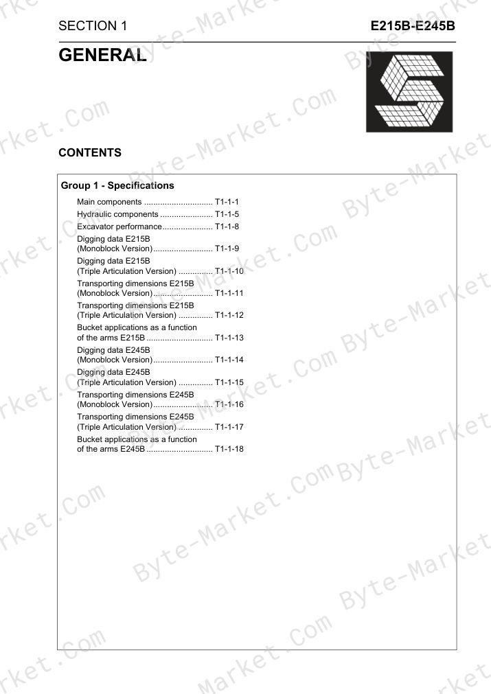
T1 — GENERAL / Group 1 - Specifications
- Main components (p. T1-1-1)
- Hydraulic components (p. T1-1-5)
- Excavator performance (p. T1-1-8)
- Digging data E215B (Monoblock Version) (p. T1-1-9)
- Digging data E215B (Triple Articulation Version) (p. T1-1-10)
- Transporting dimensions E215B (Monoblock Version) (p. T1-1-11)
- Transporting dimensions E215B (Triple Articulation Version) (p. T1-1-12)
- Bucket applications as a function of the arms E215B (p. T1-1-13)
- Digging data E245B (Monoblock Version) (p. T1-1-14)
- Digging data E245B (Triple Articulation Version) (p. T1-1-15)
- Transporting dimensions E245B (Monoblock Version) (p. T1-1-16)
- Transporting dimensions E245B (Triple Articulation Version) (p. T1-1-17)
- Bucket applications as a function of the arms E245B (p. T1-1-18)
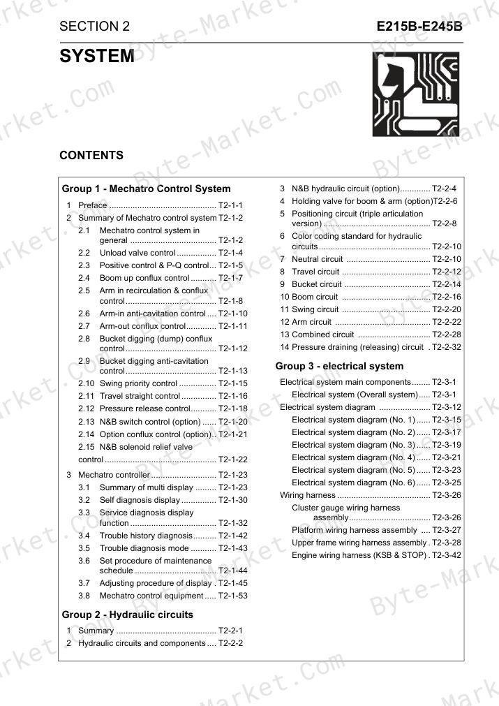
T2 — SYSTEM / Group 1 - Mechatro Control System
- 1 Preface (p. T2-1-1)
- 2 Summary of Mechatro control system (p. T2-1-2)
- 2.1 Mechatro control system in general (p. T2-1-2)
- 2.2 Unload valve control (p. T2-1-4)
- 2.3 Positive control & P-Q control (p. T2-1-5)
- 2.4 Boom up conflux control (p. T2-1-7)
- 2.5 Arm in recirculation & conflux control (p. T2-1-8)
- 2.6 Arm-in anti-cavitation control (p. T2-1-10)
- 2.7 Arm-out conflux control (p. T2-1-11)
- 2.8 Bucket digging (dump) conflux control (p. T2-1-12)
- 2.9 Bucket digging anti-cavitation control (p. T2-1-13)
- 2.10 Swing priority control (p. T2-1-15)
- 2.11 Travel straight control (p. T2-1-16)
- 2.12 Pressure release control (p. T2-1-18)
- 2.13 N&B switch control (option) (p. T2-1-20)
- 2.14 Option conflux control (option) (p. T2-1-21)
- 2.15 N&B solenoid relief valve control (p. T2-1-22)
- 3 Mechatro controller (p. T2-1-23)
- 3.1 Summary of multi display (p. T2-1-23)
- 3.2 Self diagnosis display (p. T2-1-30)
- 3.3 Service diagnosis display function (p. T2-1-32)
- 3.4 Trouble history diagnosis (p. T2-1-42)
- 3.5 Trouble diagnosis mode (p. T2-1-43)
- 3.6 Set procedure of maintenance schedule (p. T2-1-44)
- 3.7 Adjusting procedure of display . (p. T2-1-45)
- 3.8 Mechatro control equipment (p. T2-1-53)
T2 — SYSTEM / Group 2 - Hydraulic circuits
- 1 Summary (p. T2-2-1)
- 2 Hydraulic circuits and components (p. T2-2-2)
- 3 N&B hydraulic circuit (option) (p. T2-2-4)
- 4 Holding valve for boom & arm (option) (p. T2-2-6)
- 5 Positioning circuit (triple articulation version) (p. T2-2-8)
- 6 Color coding standard for hydraulic circuits (p. T2-2-10)
- 7 Neutral circuit (p. T2-2-10)
- 8 Travel circuit (p. T2-2-12)
- 9 Bucket circuit (p. T2-2-14)
- 10 Boom circuit (p. T2-2-16)
- 11 Swing circuit (p. T2-2-20)
- 12 Arm circuit (p. T2-2-22)
- 13 Combined circuit (p. T2-2-28)
- 14 Pressure draining (releasing) circuit . (p. T2-2-32)
T2 — SYSTEM / Group 3 - electrical system
- Electrical system main components (p. T2-3-1)
- Electrical system (Overall system) (p. T2-3-1)
- Electrical system diagram (p. T2-3-12)
- Electrical system diagram (No. 1) (p. T2-3-15)
- Electrical system diagram (No. 2) (p. T2-3-17)
- Electrical system diagram (No. 3) (p. T2-3-19)
- Electrical system diagram (No. 4) (p. T2-3-21)
- Electrical system diagram (No. 5) (p. T2-3-23)
- Electrical system diagram (No. 6) (p. T2-3-25)
- Wiring harness (p. T2-3-26)
- Cluster gauge wiring harness assembly (p. T2-3-26)
- Platform wiring harness assembly (p. T2-3-27)
- Upper frame wiring harness assembly . (p. T2-3-28)
- Engine wiring harness (KSB & STOP) . (p. T2-3-42)
Section and group overview
- Section 3 — COMPONENT OPERATION
- Group 1 — Hydraulic Pump Assy
- Group 2 — Pilot Valve
- Group 3 — Control Valve
- Group 4 — Swing Device
- Group 5 — Travel Device
- Group 6 — Swivel Joint
- Group 7 — Cylinders
- Group 8 — Air Conditioner system
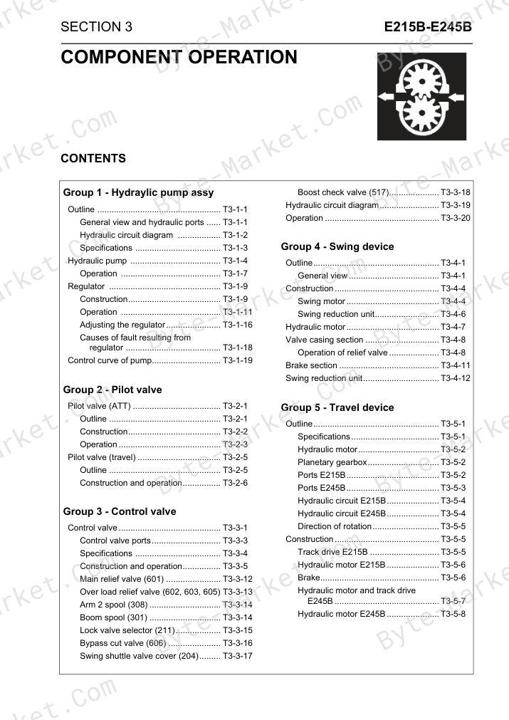
T3 — COMPONENT OPERATION / Group 1 - Hydraylic pump assy
- Outline (p. T3-1-1)
- General view and hydraulic ports (p. T3-1-1)
- Hydraulic circuit diagram (p. T3-1-2)
- Specifications (p. T3-1-3)
- Hydraulic pump (p. T3-1-4)
- Operation (p. T3-1-7)
- Regulator (p. T3-1-9)
- Construction (p. T3-1-9)
- Operation (p. T3-1-11)
- Adjusting the regulator (p. T3-1-16)
- Causes of fault resulting from regulator (p. T3-1-18)
- Control curve of pump (p. T3-1-19)
T3 — COMPONENT OPERATION / Group 2 - Pilot valve
- Pilot valve (ATT) (p. T3-2-1)
- Outline (p. T3-2-1)
- Construction (p. T3-2-2)
- Operation (p. T3-2-3)
- Pilot valve (travel) (p. T3-2-5)
- Outline (p. T3-2-5)
- Construction and operation (p. T3-2-6)
T3 — COMPONENT OPERATION / Group 3 - Control valve
- Control valve (p. T3-3-1)
- Control valve ports (p. T3-3-3)
- Specifications (p. T3-3-4)
- Construction and operation (p. T3-3-5)
- Main relief valve (601) (p. T3-3-12)
- Over load relief valve (602, 603, 605) (p. T3-3-13)
- Arm 2 spool (308) (p. T3-3-14)
- Boom spool (301) (p. T3-3-14)
- Lock valve selector (211) (p. T3-3-15)
- Bypass cut valve (606) (p. T3-3-16)
- Swing shuttle valve cover (204) (p. T3-3-17)
- Boost check valve (517) (p. T3-3-18)
- Hydraulic circuit diagram (p. T3-3-19)
- Operation (p. T3-3-20)
T3 — COMPONENT OPERATION / Group 4 - Swing device
- Outline (p. T3-4-1)
- General view (p. T3-4-1)
- Construction (p. T3-4-4)
- Swing motor (p. T3-4-4)
- Swing reduction unit (p. T3-4-6)
- Hydraulic motor (p. T3-4-7)
- Valve casing section (p. T3-4-8)
- Operation of relief valve (p. T3-4-8)
- Brake section (p. T3-4-11)
- Swing reduction unit (p. T3-4-12)
T3 — COMPONENT OPERATION / Group 5 - Travel device
- Outline (p. T3-5-1)
- Specifications (p. T3-5-1)
- Hydraulic motor (p. T3-5-2)
- Planetary gearbox (p. T3-5-2)
- Ports E215B (p. T3-5-2)
- Ports E245B (p. T3-5-3)
- Hydraulic circuit E215B (p. T3-5-4)
- Hydraulic circuit E245B (p. T3-5-4)
- Direction of rotation (p. T3-5-5)
- Construction (p. T3-5-5)
- Track drive E215B (p. T3-5-5)
- Hydraulic motor E215B (p. T3-5-6)
- Brake (p. T3-5-6)
- Hydraulic motor and track drive E245B (p. T3-5-7)
- Hydraulic motor E245B (p. T3-5-8)
T3 — COMPONENT OPERATION / Group 6 - Swivel joint
- Outline (p. T3-6-1)
- Construction (p. T3-6-2)
- Operation (p. T3-6-3)
T3 — COMPONENT OPERATION / Group 7 - Cylinders
- Outline (p. T3-7-1)
- Construction (p. T3-7-2)
- Boom cylinder (p. T3-7-2)
- Arm cylinder (p. T3-7-3)
- Bucket cylinder (p. T3-7-4)
- Positioning (p. T3-7-5)
- Operation (p. T3-7-6)
T3 — COMPONENT OPERATION / Group 8 - Air conditioner system
- Basic system of air conditioner (HVAC air conditioner) (p. T3-8-1)
- Air cycle (p. T3-8-1)
- Auto air conditioner system outline (p. T3-8-2)
- Component and construction (p. T3-8-3)
- Piping (p. T3-8-7)
- Air dryer assy (p. T3-8-10)
- Components parts (p. T3-8-13)
- Precautions to be exercised in operation (p. T3-8-17)
- Disassembly and assembly of unit (p. T3-8-18)
- Charging refrigerant (p. T3-8-22)
- Precautions to be exercised in operation (p. T3-8-22)
- Operating procedure (p. T3-8-23)
- Electric circuit (p. T3-8-27)
- Wiring diagram and connectors (p. T3-8-28)
- Structure and operation of each functional parts and the inspection (p. T3-8-29)
- Troubleshooting (p. T3-8-33)
- Self diagnosis function on display of panel (p. T3-8-40)
- Explanation of monitor mode (p. T3-8-42)
Section and group overview
- Section 4 — OPERATIONAL PERFORMANCE TEST
- Group 1 — Introduction
- Group 2 — Standard Performances
- Group 3 — Test Procedures
- Group 4 — Mechatro Controller
T4 — OPERATIONAL PERFORMANCE TEST / Group 1 - Introduction
- How to Use the Maintenance Standard and Cautions to Be Exercised (p. T4-1-1)
- Preparation for Performance Tests (p. T4-1-2)
T4 — OPERATIONAL PERFORMANCE TEST / Group 2 - Standard Performances
- Performance Inspection Standard Table (p. T4-2-1)
T4 — OPERATIONAL PERFORMANCE TEST / Group 3 - Test Procedures
- Measurement of engine speed (p. T4-3-1)
- Measurement of hydraulic pressure (p. T4-3-2)
- Measuring travel performances (p. T4-3-7)
- Measuring swing performances (p. T4-3-11)
- Measuring attachment operating performances (p. T4-3-15)
- Measuring performances of swing bearing (p. T4-3-17)
T4 — OPERATIONAL PERFORMANCE TEST / Group 4 - Mechatro Controller
- Engine control input/output (p. T4-4-1)
- Engine control (p. T4-4-2)
- Engine control equipment (p. T4-4-3)
- Adjustment of mechatro controller output (A-B-C adjustment) (p. T4-4-4)
Section and group overview
- Section 5 — TROUBLESHOOTING
- Group 1 — Troubleshooting (by Error Codes)
- Group 2 — Troubleshooting (by trouble)
- Group 3 — Troubleshooting (Trouble diagnosis mode)
T5 — TROUBLESHOOTING / Group 1 - Troubleshooting (by Error
- Codes) 1. Judgment of actual thing at site (p. T5-1-1)
- 2. Classification on failure and troubleshooting (p. T5-1-2)
- 3. The blown fuse of Mechatro Controller (p. T5-1-2)
- 4. Troubleshooting by Error Codes (p. T5-1-2)
T5 — TROUBLESHOOTING / Group 2 - Troubleshooting (by trouble)
- 1. Hydraulic system (p. T5-2-1)
- 2. Electric systems (p. T5-2-30)
- 2.1 Wiring checking procedure (p. T5-1-30)
- 2.2 Trouble (p. T5-1-33)
T5 — TROUBLESHOOTING / Group 3 - Troubleshooting (Trouble
- diagnosis mode) 1. Trouble diagnosis mode (p. T5-3-1)
Section and group overview
- Section 1 — GENERAL INFORMATION
- Group 1 — Precautions for Disassembly and Assembly
- Group 2 — Tightening Torque
- Section 2 — UPPERSTRUCTURE
- Group 1 — Upperstructure
- Group 2 — Pump device
- Group 3 — Control valve
- Group 4 — Swing device
- Group 5 — Pilot valve
- Section 3 — UNDERCARRIAGE
- Group 1 — Swing bearing
- Group 2 — Travel device
- Group 3 — Swivel joint
- Group 4 — Track adjuster
- Group 5 — Front idler
- Group 6 — Upper and lower roller
- Group 7 — Tracks
- Section 4 — FRONT ATTACHMENT
- Group 1 — Front attachment
W1 — GENERAL INFORMATION / Group 1 - Precautions for Disassembly
- and Assembly Precautions for Disassembly and Assembly (p. W1-1-1)
W1 — GENERAL INFORMATION / Group 2 - Tightening Torque
- Torque Chart (p. W1-2-1)
- Piping Joint (p. W1-2-4)
W2 — UPPERSTRUCTURE / Group 1 - Upperstructure
- Removal and installation of upperstructure (p. W2-1-1)
- Preparation (p. W2-1-1)
- Removal of upperstructure (p. W2-1-1)
- Removal and installation of the cab (p. W2-1-2)
- Removal of the cab (p. W2-1-2)
- Installation of the cab (p. W2-1-3)
- Removal and installation of counterweight (p. W2-1-4)
- Removal of counterweight (p. W2-1-4)
- Installation of counterweight (p. W2-1-5)
- Disconnecting hoses of swivel joint lower side (p. W2-1-6)
- Swivel joint lower side hoses (p. W2-1-7)
- Removal and installation of main frame. (p. W2-1-8)
- Removal of main frame (p. W2-1-8)
- Installation of main frame (p. W2-1-9)
W2 — UPPERSTRUCTURE / Group 2 - Pump device
- Removal and installation of hydraulic pump device (p. W2-2-1)
- Preparation (p. W2-2-1)
- Removal (p. W2-2-1)
- Installation (p. W2-2-1)
- Disassembly and assembly of pump device (p. W2-2-2)
- Disassembly hydraulic pump device (p. W2-2-3)
- Assembly (p. W2-2-7)
- Maintenance standard (p. W2-2-11)
- Disassembly and assembly of regulator (p. W2-2-12)
- Disassembly of regulator (p. W2-2-14)
- Assembly of regulator (p. W2-2-18)
- Disassembly and assembly of pto gear casing (p. W2-2-21)
- Disassembly (p. W2-2-22)
- Assembly (p. W2-2-23)
- Maintenance standard (p. W2-2-23)
W2 — UPPERSTRUCTURE / Group 2 - Control valve
- Removal and installation of control valveW2-3-1 Preparation (p. W2-3-1)
- Removal of control valve (p. W2-3-1)
- Installation of control valve (p. W2-3-2)
- Control valve ports (p. W2-3-3)
- Assembly and disassembly of control valve (p. W2-3-12)
- Preparation for disassembly (p. W2-3-12)
- Disassembly (p. W2-3-13)
- Inspection after disassembly (p. W2-3-25)
- Assembly (p. W2-3-25)
- Maintenance standards (p. W2-3-32)
W2 — UPPERSTRUCTURE / Group 4 - Swing device
- Removal and installation of swing deviceW2-4-1 Preparation (p. W2-4-1)
- Removal (p. W2-4-2)
- Installation (p. W2-4-3)
- Disassembly and assembly of swing motor (p. W2-4-4)
- Preliminary operations (p. W2-4-5)
- Disassembly (p. W2-4-5)
- Assembly (p. W2-4-7)
- Disassembly and assembly of swing reducer (p. W2-4-9)
- Preliminary operations (p. W2-4-10)
- Disassembly (p. W2-4-10)
- Assembly (p. W2-4-13)
- Maintenance standards (p. W2-4-18)
- Swing motor (p. W2-4-18)
- Swing reduction gear (p. W2-4-19)
W2 — UPPERSTRUCTURE / Group 5 - Pilot valve
- Removal and installation of right and left pilot valve (p. W2-5-1)
- Preparation (p. W2-5-1)
- Removal (p. W2-5-1)
- Installation (p. W2-5-2)
- Removal and installation of travel pilot valve (p. W2-5-3)
- Preparation (p. W2-5-3)
- Removal (p. W2-5-3)
- Installation (p. W2-5-4)
- Disassembly right and left pilot valve (p. W2-5-5)
- Disassembly right and left pilot valve (p. W2-5-6)
- Assembly right and left pilot valve (p. W2-5-9)
- Assembly right and left pilot valve (p. W2-5-10)
- Pilot valve (for travel) (p. W2-5-13)
- Construction (p. W2-5-13)
- Disassembly and assembly (p. W2-5-14)
- Drain of hydraulic pilot control unit (p. W2-5-21)
W3 — UNDERCARRIAGE / Group 1 - Swing bearing
- Removal and installation of swing bearing (p. W3-1-1)
W3 — UNDERCARRIAGE / Group 2 - Travel device
- Removal and installation of travel device (E215B) (p. W3-2-1)
- Disassembly travel device (p. W3-2-2)
- Disassembly and assembly of travel device (E215B) (p. W3-2-3)
- Maintenance standard (p. W3-2-61)
- Sprocket (p. W3-2-61)
- Removal and installation of travel device (E245B) (p. W3-2-63)
- Disassembly procedure of travel device (E245B) (p. W3-2-67)
- Assembling procedure of travel device (E245B) (p. W3-2-80)
- Motor (p. W3-2-88)
- Tool table (p. W3-2-98)
W3 — UNDERCARRIAGE / Group 3 - Swivel joint
- Removal and installation of swivel joint . (p. W3-3-1)
- Swivel joint disassembly and assembly. (p. W3-3-4)
- Maintenance standard (p. W3-3-9)
W3 — UNDERCARRIAGE / Group 4 - Track adjuster
- Removal and installation of track adjuster (with front idler) (p. W3-4-1)
- Disassembly and assembly track adjuster (p. W3-4-2)
- Tool table (p. W3-4-6)
W3 — UNDERCARRIAGE / Group 5 - Front idler
- Disassembly and assembly front idler assy (p. W3-5-1)
- Maintenance standard (p. W3-5-4)
- Tool table (p. W3-5-4)
W3 — UNDERCARRIAGE / Group 6 - Upper and lower roller
- Removal and installation of upper roller (p. W3-6-1)
- Removal and installation of lower roller (p. W3-6-4)
- Upper roller disassembly (p. W3-6-7)
- Upper roller assembly (p. W3-6-7)
- Lower roller disassembly (p. W3-6-11)
- Lower roller assembly (p. W3-6-13)
- Maintenance standard (p. W3-6-15)
- Tool table (p. W3-6-16)
W3 — UNDERCARRIAGE / Group 7 - Tracks
- Removal and installation of tracks (p. W3-7-1)
- Maintenance standard (p. W3-7-5)
- Tool table (p. W3-7-7)
W4 — FRONT ATTACHMENT / Group 1 - Front attachment
- Front attachment removal and installation (p. W4-1-1)
- Monoblock version (p. W4-1-1)
- Maintenance (p. W4-1-6)
- Triple articulation version (p. W4-1-7)
- Maintenance (p. W4-1-12)
- Standard dimensions for arm and bucket connection (p. W4-1-13)
- Replacement of bucket (p. W4-1-14)
- Removing the bucket (p. W4-1-14)
- Installing the bucket (p. W4-1-14)
- Bucket play adjustment (p. W4-1-14)
- Bucket teeth replacement (p. W4-1-15)
- Cylinders removal and installation (p. W4-1-16)
- Bucket Cylinder removal (p. W4-1-16)
- Bucket Cylinder installation (p. W4-1-18)
- Arm cylinder removal (p. W4-1-19)
- Arm cylinder installation (p. W4-1-20)
- Boom cylinders removal (p. W4-1-21)
- Boom cylinders installation (p. W4-1-22)
- Positioner cylinder removal (p. W4-1-23)
- Positioner cylinder installation (p. W4-1-24)
- Cylinders assembly and disassembly (p. W4-1-25)
- Bucket cylinder (p. W4-1-25)
- Arm cylinder (p. W4-1-28)
- Positioner cylinder (p. W4-1-31)
- Boom cylinders (p. W4-1-34)
- Special tools (p. W4-1-37)
- Maintenance standard: rod (p. W4-1-38)
Delivery
Digital PDF format. No physical book is included.


No questions found.