
About this manual
This OEM New Holland Repair Manual provides workshop information for the LS160 and LS170 skid-steer loaders in PDF format. The contents include GENERAL INFORMATION.
The indexed contents provide page references for the documented systems and topics. Use Manual contents to find the system or task you need, and check Manual details for model coverage and publication information.
Manual details
- Manufacturer
- New Holland
- Manual type
- Repair Manual
- Equipment type
- Skid-Steer Loader
- Models
- LS160 and LS170
- Document number
- 87036983
- Text search
- Available
- PDF navigation
- PDF bookmarks
- Document quality
- High — clear, readable text, illustrations and diagrams.
Product highlights
Electrical systems
The manual includes wiring diagrams, electrical troubleshooting, and pinouts.
Hydraulic systems
The manual includes hydraulic valve-adjustment material.
Specifications and settings
The manual includes reference information for capacities.
Special tools
A special-tools section is included.
Applicability and limitations
The publisher's Contents identifies Book 1 (87042552), Book 2 (87036985), Book 3 (87036986), and Book 4 (87036987).
Systems and topics in this manual
GENERAL INFORMATION
Parts and Accessories; Model Codes; Precautionary Statements.
ENGINE
LS160 - N844 (Before Engine S/N 124735) LS170 - N844T (All); LS160 - N844 (Tier II Engine, S/N 124735 and after).
REAR DRIVE AXLE (GEARBOXES)
Gearbox removal, disassembly, and parts inspection.
HYDROSTATIC TRANSMISSION
Charge-system pressure test, pump disassembly, and motor reassembly.
BRAKES AND CONTROLS
Parking-brake inspection and testing.
HYDRAULIC SYSTEM
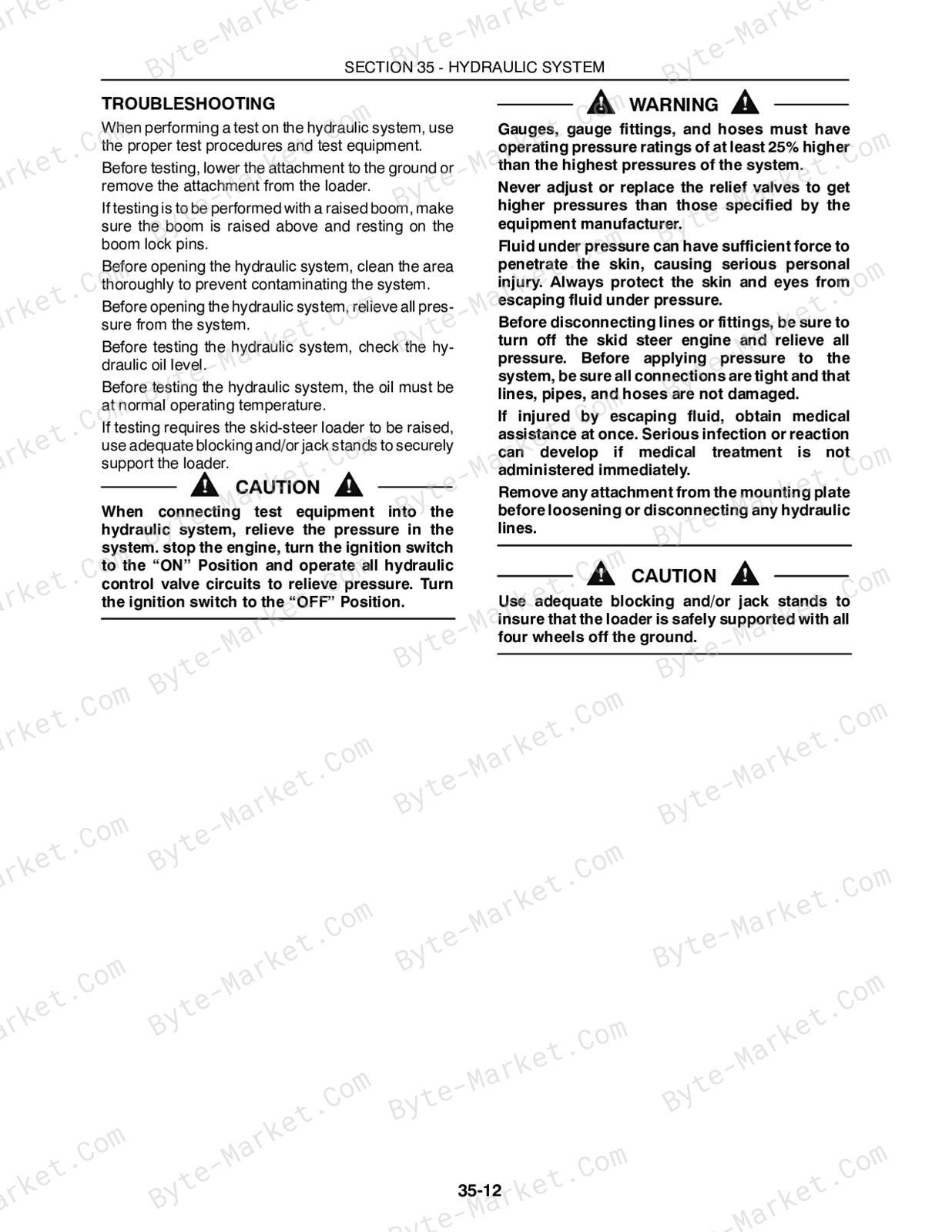
Boom cylinder pivot pins; main system pressure tests; control-valve disassembly and inspection.
TOWING HOOKS AND BALLASTING
Rear counterweights and counterweight support removal.
FRAMES
ROPS frame removal and reinstallation.
AXLES AND WHEELS
Axle-housing removal; drive-chain and sprocket removal; tire and track installation.
CAB CLIMATE CONTROL
Heater/defroster troubleshooting and heater control wire diagram.
ELECTRICAL SYSTEM
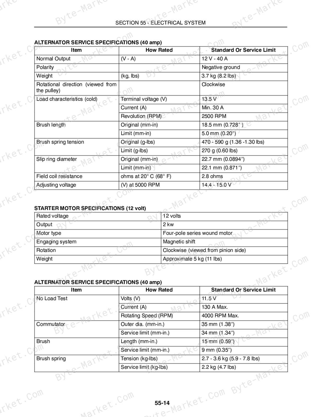
Electronic instrument cluster; diagnostic and setup modes; electrical circuits.
FRONT LOADER (BOOM AND MOUNTING PLATE)
Boom lock pins and linkage; attachment mounting plate; bucket cutting-edge replacement.
ACCESSORIES
Back-up alarm, engine block heater, and high-flow hydraulics.
PLATFORMS, CAB, BODYWORK, AND DECALS
Seat removal, cab inner shell, and safety decals.
Manual contents
The source sections and independent chapters are listed below with their major indexed topics. Detailed procedures remain within those chapters in the PDF. References use physical PDF pages; unnumbered group headings follow the printed index.
- SECTION 00 - GENERAL INFORMATION — p. 23
- Introduction — p. 24
- About Improvements — p. 24
- Company Policy — p. 25
- Parts and Accessories — p. 25
- Model Codes — p. 25
- Precautionary Statements — p. 26
- General Safety Information — p. 29
- Machine Model and Serial Number Location — p. 31
- Engine Model and Serial Number Location — p. 31
- Installation of Adjustable Fittings in Straight Thread O Ring Bosses — p. 34
- Standard Torque Data for Hydraulic Tubes and Fittings — p. 34
- Pipe Thread Fitting Torque — p. 35
- Lubricants and Coolants — p. 35
- Sealants — p. 35
- Properly Support a Raised Machine — p. 36
- Properly Support Boom on Boom Lock Pins — p. 36
- Raising Boom Without Hydraulic Oil Flow — p. 36
- Reattaching Cylinders After Repair with Boom Resting on Boom Lock Pins — p. 39
- Major Unit Overhaul — p. 40
- Cab and Boom Tilt Procedure — p. 41
- Craning the Skid Steer — p. 47
- Special Tools — p. 50
- Specifications — p. 51
- SECTION 10 - ENGINE — p. 59
-
Chapter 1 - LS160 - N844 (Before Engine S/N 124735) LS170 - N844T (All) — p. 59 — expand topics
- General Engine Information — p. 61
- General Description — p. 61
- Engine Component Descriptions — p. 61
- Engine Model and Serial Number Location — p. 63
- Turbocharger Lubrication — p. 63
- Safety Precautions — p. 64
- General Engine Specifications — p. 65
- Troubleshooting — p. 69
- LS170 - Excessive Oil Consumption — p. 73
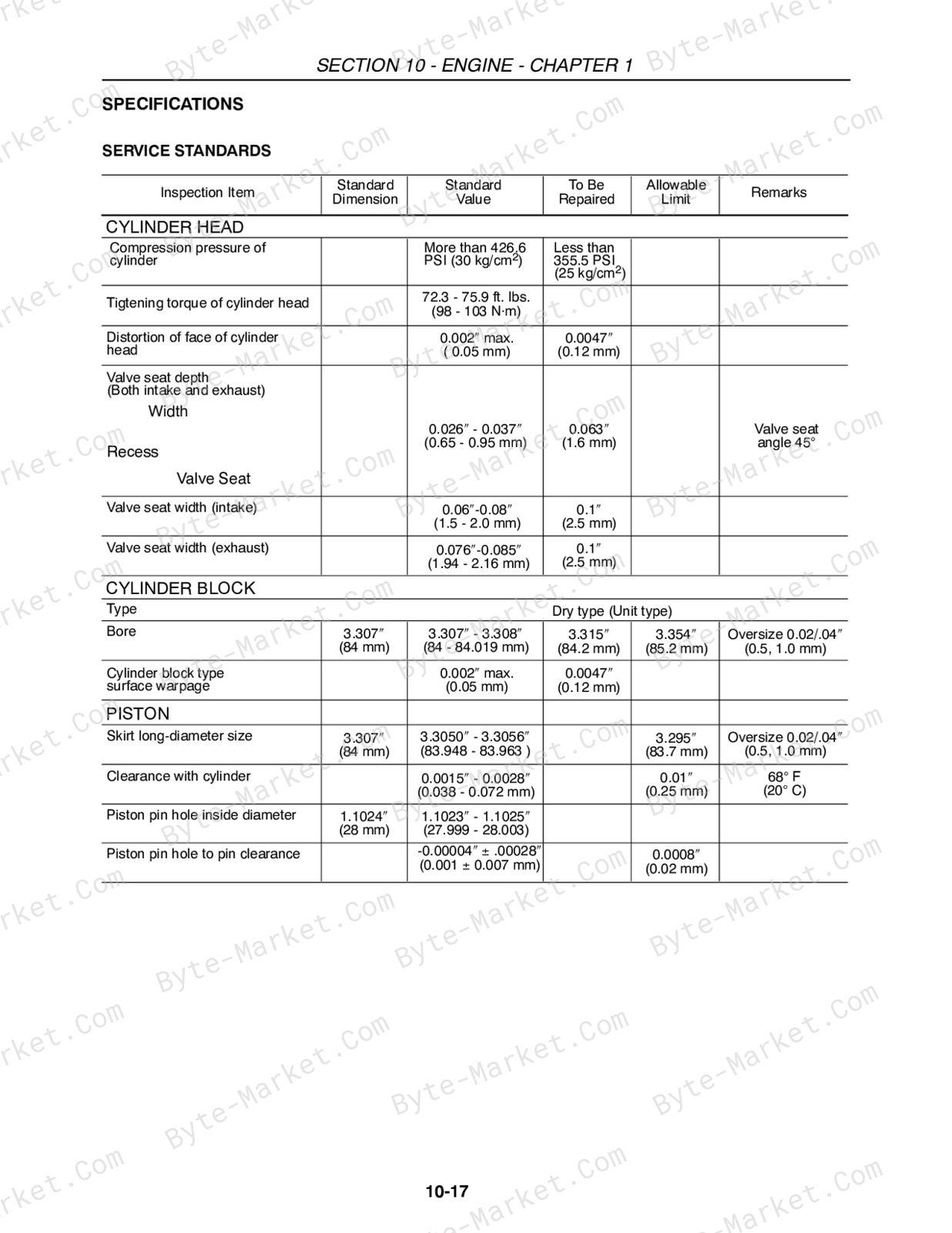
- Specifications - Service Standards — p. 75
- Torque Specifications — p. 79
- Engine Components Electrical Diagram — p. 80
- Engine Removal — p. 81
- Engine Disassembly Sequence — p. 86
- Engine Component Maintenance — p. 94
- Valve Seat — p. 97
- Cylinder Block — p. 99
- Piston and Piston Rings — p. 100
- Connecting Rod — p. 103
- Bearing Holder — p. 105
- Crankshaft Bearing (Bushing) — p. 106
- Crankshaft — p. 108
- Flywheel and Ring Gear — p. 110
- Camshaft Assembly — p. 110
- Camshaft Gear and Bearing Assembly — p. 111
- Timing Gear — p. 111
- Oil Pump — p. 112
- Oil Filter — p. 114
- Water Pump Assembly and Thermostat Housing — p. 114
- Governor — p. 116
- Governor Operation — p. 118
- Engine Reassembly Sequence — p. 120
- Crankshaft and Bearing Holder Assembly — p. 121
- Rear Oil Seal — p. 121
- Backplate/Flywheel Housing — p. 122
- Flywheel — p. 122
- Oil Intake and Oil Strainer — p. 123
- Oil Sump — p. 123
- Dipstick and Tube — p. 123
- Front Plate — p. 123
- Crankshaft Pulley — p. 125
- Injection Pump Installation — p. 125
- Adjusting the Fuel Injection Timing — p. 126
- Spill Timing Procedure — p. 127
- Reinstallation of Engine into Skid Steer Frame — p. 134
- How to Operate the Engine After Overhaul — p. 136
- Cooling System — p. 137
- Radiator — p. 139
- Diesel Fuel Storage — p. 141
- Fuel System Components — p. 141
- Cold Start Aid — p. 143
- Fuel Filter System — p. 143
- Priming the Fuel System — p. 144
- Fuel System Testing — p. 145
- Fuel System Components — p. 148
- Fuel Injection Timing — p. 154
- Turbocharger - LS170 N844T Engine — p. 159
- Turbocharger Removal — p. 161
- Miscellaneous Engine Electrical — p. 174
- Special Tools — p. 177
-
Chapter 2 -- LS160 - N844 (Tier II Engine, S/N 124735 and after) — p. 179 — expand topics
- General Description — p. 181
- Engine Component Descriptions — p. 181
- Engine Model and Serial Number Location — p. 183
- Safety Precautions — p. 184
- General Engine Specifications — p. 185
- Troubleshooting — p. 187
- Specifications - Service Standards — p. 191
- Torque Specifications — p. 195
- Engine Components Electrical Diagram — p. 196
- Engine Removal — p. 197
- Engine Disassembly Sequence — p. 202
- Engine Component Maintenance — p. 210
- Valve Seat — p. 213
- Cylinder Block — p. 215
- Piston and Piston Rings — p. 215
- Connecting Rod — p. 218
- Bearing Holder — p. 220
- Crankshaft — p. 223
- Flywheel and Ring Gear — p. 225
- Camshaft Assembly — p. 225
- Camshaft Gear and Bearing Assembly — p. 226
- Timing Gear — p. 226
- Oil Pump — p. 227
- Oil Filter — p. 229
- Water Pump Assembly and Thermostat Housing — p. 229
- Governor — p. 231
- Governor Operation — p. 233
- Engine Reassembly Sequence — p. 235
- Crankshaft and Bearing Holder Assembly — p. 236
- Rear Oil Seal — p. 236
- Backplate/Flywheel Housing — p. 237
- Flywheel — p. 237
- Piston and Connecting Rod — p. 237
- Oil Intake and Oil Strainer — p. 238
- Oil Sump — p. 238
- Dipstick and Tube — p. 238
- Front Plate — p. 238
- Crankshaft Pulley — p. 240
- Injection Pump Installation — p. 240
- Adjusting the Fuel Injection Timing — p. 241
- Reinstallation of Engine into Skid Steer Frame — p. 245
- How to Operate the Engine After Overhaul — p. 247
- Cooling System — p. 248
- Radiator — p. 250
- Fuel System — p. 252
- Fuel Specifications — p. 252
- Diesel Fuel — p. 252
- Diesel Fuel Storage — p. 252
- Fuel System Components — p. 253
- Cold Start Aid — p. 255
- Fuel Filter System — p. 255
- Priming the Fuel System — p. 256
- Fuel System Testing — p. 257
- Fuel System Components — p. 260
- Special Tools — p. 270
-
- SECTION 27 - REAR DRIVE AXLE (GEARBOXES) — p. 272
- SECTION 29 - HYDROSTATIC TRANSMISSION — p. 290
- SECTION 33 - BRAKES AND CONTROLS — p. 408
- SECTION 35 - HYDRAULIC SYSTEM — p. 430
- SECTION 37 - TOWING HOOKS AND BALLASTING — p. 540
- SECTION 39 - FRAMES — p. 542
- SECTION 44 - AXLES AND WHEELS — p. 552
- SECTION 50 - CAB CLIMATE CONTROL — p. 576
- SECTION 55 - ELECTRICAL SYSTEM — p. 596
- SECTION 82 - FRONT LOADER (BOOM AND MOUNTING PLATE) — p. 756
- SECTION 88 - ACCESSORIES — p. 796
- SECTION 90 - PLATFORMS, CAB, BODYWORK, AND DECALS — p. 830
Technical reference
Reference tables include fluid and system capacities for service specifications, limits, adjustment and repair reference data. Use the values and conditions in the PDF for the applicable model and procedure.
- Fluid reference: fluid and system capacities.
Delivery
This manual is supplied as a digital PDF file and is available for instant download after purchase. No physical media is shipped.
References
New Holland Repair Manual for Skid-Steer Loader, document code 87036983, PDF edition.


No questions found.