
About this manual
Published by New Holland, this OEM Repair Manual is a PDF reference for the tractors listed in Manual details. The contents include General.
The indexed contents provide page references for the documented systems and topics. Refer to Manual contents for section and page references, and to Manual details for model coverage and publication information.
Manual details
- Manufacturer
- New Holland
- Manual type
- Repair Manual
- Equipment type
- Tractor
- Models
- TS100A, TS110A, TS115A, TS125A, TS130A, TS135A, T6010, T6020, T6030, T6050, and T6070
- Document number
- 87693272
- Text search
- Available
- PDF navigation
- PDF bookmarks
- Document quality
- High — clear, readable text, illustrations and diagrams.
Product highlights
Electrical systems
The manual includes wiring diagrams, electrical troubleshooting, connector views, and pinouts.
Hydraulic systems
The manual includes hydraulic circuit diagrams, hydraulic pressure-test material, and hydraulic valve-adjustment material.
Specifications and settings
The manual includes reference information for pressure specifications.
Special tools
A special-tools section is included.
Maintenance
The manual includes a maintenance schedule.
Applicability and limitations
Engine Repair Manual (87661796) is required for engine repair of T6010, T6020, T6030, T6050, and T6070.
The publisher's Contents identifies Book 1 (87515312), Book 2 (87693273), Book 3 (87515314), Book 4 (87693274), Book 5 (87515316), Book 6 (87693275), Book 7 (87515318), Book 8 (87693276), Book 9 (87515320), Book 10 (87515321), Book 11 (87515322), Book 12 (87515323), Book 13 (87515324), Book 14 (87515325), Book 15 (87515326), Book 16 (87515327), and Book 17 (87515328).
Systems and topics in this manual
General
Health and Safety; Ecology and the Environment; Product Identification.
Separating The Tractor
Separating Front Axle and Front Support from the Engine; Front Axle and Front Support; Front Axle to Support Shim Thickness Calculation.
Engine
CNH Engine - F4DE0484A (4 Cylinder Common Rail Electronic), Cooling, and Lubrication.
Clutch
Inspection and Repair; Hydraulic Release Bearing / Slave Cylinder.
Transmission Systems
16 x 16 Transmission, Input Sensors, and Transmission Oil Temperature Sensor.
Drive Lines
Manual Four Wheel Drive, Automatic Four Wheel Drive, and Four Wheel Drive Off.
Mechanical Front Axle
Hydraulic Differential Lock, Standard Axle, and Multi-Wet Plate Clutch Differential.
Mechanical Rear Wheel Drive
Pinion, Crown Wheel and Differential; Final Drive; Rear Differential Lock Assembly - Multi-Wet Plate Clutch.
Power Take-Off
External PTO Controls (except N. America), Auto PTO Function (if fitted), and Engine Power Management.
Braking System
Tractor Brakes, Control Circuit, and Front Brake Valve.
Hydraulic Systems
Hydraulic Circuits, Circuit Identification, and High Pressure Circuit.
Steering
Hydrostatic Steering System, Neutral Position, and Right Hand Turn.
Front Axle And Wheels
Hub and Spindle; Front Wheel Hub; Spindle Assembly.
Auxiliary Units
Air Conditioning, Compressor, and Safety Precautions.
Electrical System
Electrical Introduction; Electrical System and Fuses; CAN Architecture - 16 x 16 Models.
Manual contents
Expanded contents follow the source sections and headings in order. Page numbers below refer to physical PDF pages. Expand a chapter to show its topics. Unnumbered group headings follow the printed source index.
- TSA SERIES and T6000 SERIES REPAIR MANUAL Complete Contents — p. 1
- SECTION 00 - General — p. 93
-
Chapter 1 -- General Information — p. 93 — expand topics
- General Instructions — p. 94
- Precautionary Statements
- Health and Safety — p. 99
- Ecology and the Environment — p. 107
- Product Identification — p. 108
- International Symbols — p. 111
- Specifications -- Plus/Deluxe Models — p. 112
- General Dimensions — p. 112
- Specifications -- Standard Models — p. 119
- General Dimensions — p. 119
- Minimum Hardware Tightening Torques — p. 126
- HEALTH AND SAFETY PRECAUTIONS — p. 99
- ACIDS AND ALKALIS
- ADHESIVES AND SEALERS -- see Fire — p. 100
- ANTIFREEZE -- see Fire, Solvents e.g. Isopropanol, Ethylene Glycol, Methanol
- ARC WELDING -- see Welding — p. 100
- BATTERY ACIDS -- see Acids and Alkalis — p. 100
- BRAKE AND CLUTCH FLUIDS (Polyalkylene Glycols) -- see Fire — p. 101
- BRAZING -- see Welding — p. 101
- CHEMICAL MATERIALS -- GENERAL -- see Legal Aspects
- DO’S — p. 101
- DO NOTS — p. 101
- CORROSION PROTECTION MATERIALS -- see Solvents, Fire
- DUSTS — p. 102
- ELECTRIC SHOCK — p. 102
- EXHAUST FUMES — p. 102
- FIBRE INSULATION -- see Dusts — p. 102
- FIRE -- see Welding, Foams, Legal Aspects — p. 102
- FIRST AID — p. 102
- FOAMS -- Polyurethane -- see Fire — p. 102
- FUELS -- see Fire, Legal Aspects, Chemicals -- General, Solvents
- GAS CYLINDERS -- see Fire — p. 103
- GENERAL WORKSHOP TOOLS AND EQUIPMENT — p. 104
- LEGAL ASPECTS — p. 104
- LUBRICANTS AND GREASES — p. 104
- PAINTS -- see Solvents and Chemical Materials -- General
- SOLDER -- see Welding — p. 105
- SOLVENTS -- see Chemical Materials -- General Fuels (Kerosene), Fire
- SUSPENDED LOADS — p. 106
- WELDING -- see Fire, Electric Shock, Gas Cylinders
-
- SECTION 01 - Separating The Tractor — p. 129
- Chapter 1 -- Separating Front Axle and Front Support from the Engine — p. 129
- Tightening Torques — p. 130
- Special Tools — p. 130
- Overhaul — p. 131
- Front Axle and Front Support — p. 131
- Removal — p. 131
- Installation — p. 138
- Front Axle to Support Shim Thickness Calculation — p. 145
- Front Axle and Front Support — p. 131
- Chapter 2 -- Separating Engine and Front Support from the Transmission — p. 147
- Tightening Torques — p. 148
- Special Tools — p. 148
- Overhaul — p. 150
- Engine and Front Support from the Transmission — p. 150
- Removal — p. 150
- Installation — p. 159
- Engine and Front Support from the Transmission — p. 150
- Chapter 3 -- Separating Transmission, Engine and Front Support from the Rear Axle — p. 167
- Tightening Torques — p. 168
- Special Tools — p. 168
- Overhaul — p. 169
- Transmission, Engine and Front Support from the Rear Axle — p. 169
- Removal — p. 169
- Installation — p. 174
- Transmission, Engine and Front Support from the Rear Axle — p. 169
- Chapter 4 -- Engine Removal — p. 179
- Tightening Torques — p. 180
- Special Tools — p. 180
- Overhaul — p. 181
- Engine — p. 181
- Removal — p. 181
- Installation — p. 193
- Engine — p. 181
- Chapter 5 -- Transmission Removal — p. 205
- Tightening Torques — p. 206
- Special Tools — p. 206
- Overhaul — p. 207
- Transmission — p. 207
- Removal — p. 207
- Installation — p. 210
- Transmission — p. 207
- Chapter 6 -- Cab Removal — p. 213
- Tightening Torques — p. 214
- Tractors with Cab Suspension — p. 214
- Tractors with Standard Cab — p. 215
- Special Tools — p. 215
- Overhaul — p. 216
- Cab — p. 216
- Removal — p. 216
- Installation — p. 227
- Cab — p. 216
- Tightening Torques — p. 214
- Chapter 1 -- Separating Front Axle and Front Support from the Engine — p. 129
- SECTION 10 - Engine — p. 239
-
Chapter 1 -- CNH Engine -- F4DE0484A (4 Cylinder Common Rail Electronic) — p. 239 — expand topics
- Specifications — p. 242
- Tightening Torques — p. 247
- Special Tools — p. 252
- Description of Operation — p. 253
- Cooling — p. 253
- Lubrication — p. 254
- Lubrication System Components — p. 255
- Engine Overhaul
- Introduction
- Removal
- Disassembly
- Fuel System/Preparing Engine to Mount on Rotating Stand
- Fuel Rail — p. 259
- Cylinder Head — p. 259
- Crankcase -- External Components — p. 262
- Crank Shaft Seals — p. 263
- Sump — p. 266
- Rotating Counter Weights — p. 266
- Crankshaft — p. 267
- Camshaft — p. 269
- Bushings — p. 270
- Assembly — p. 271
- Installing the Tappets – Camshaft — p. 271
- Main Bearing Assembly — p. 272
- Crankshaft Assembly — p. 272
- Main Bearing Cap Assembly — p. 273
- Connecting Rod and Piston Assembly
- Timing — p. 275
- Crankshaft Seals and Covers — p. 277
- Rotating Counter Weights — p. 279
- Sump — p. 281
- Flywheel — p. 281
- Oil Filter/Cooler — p. 282
- Crankcase -- External Components — p. 283
- Cylinder Head/Fuel System — p. 284
- Completing the Engine — p. 293
- Introduction
- Checks, Dimensions and Repairs — p. 295
- Cylinder Block — p. 295
- Cylinder Head Mating Surface Check — p. 296
- Tappets — p. 296
- Crankshaft, Bearings — p. 297
- Main Journal Assembly Clearance — p. 299
- Crankshaft Thrust ring Clearance Check — p. 301
- Timing System — p. 302
- Camshaft — p. 302
- Checking Cam Lift and Pin Alignment — p. 302
- Bushings — p. 303
- Pistons/Connecting Rods — p. 304
- Measuring the Piston Diameter
- Piston Pins — p. 306
- Conditions for Correct Pin--Piston Coupling — p. 306
- Piston Rings — p. 306
- Connecting Rods — p. 308
- Bushings
- Checking Connecting Rods
- Checking Twisting — p. 310
- Checking Bending — p. 310
- Connecting Rod – Piston Assembly — p. 311
- Fitting Piston Rings — p. 312
- Connecting Rod Pin Assembly Clearance — p. 312
- Checking Piston Protrusion — p. 314
- Cylinder Head — p. 315
- Valve Disassembly — p. 315
- Cylinder Head Hydraulic Seal Check — p. 316
- Cylinder Head Mating Surface Check — p. 316
- Valve Dimensions — p. 317
- Decarbonizing, Checking and Grinding Valves — p. 317
- Checking the Clearance between the Valve Stem and Guide and Valve Centring — p. 318
- Valve Guides — p. 318
- Regrinding – Replacing Valve Seats — p. 318
- Valve Springs — p. 320
- Valve Installation — p. 321
- Installing the Cylinder Head — p. 321
- Checking and Adjusting Tappet Clearance — p. 323
- Fuel Supply Gear Pump — p. 324
- Normal Operating Condition — p. 324
- Condition of Overpressure at Outlet — p. 324
- Bleed Conditions — p. 324
- High--Pressure Pump CP3 — p. 325
- High--Pressure Pump Internal Structure — p. 326
- Operating Principle — p. 327
- Operation — p. 329
- Rail (Pressure Accumulator) — p. 330
- Pressure Relief Valve — p. 331
- Electro--Injector — p. 332
- InjectionStart — p. 332
- Injection End — p. 332
- Fuel Return Pressure Limiter — p. 333
- Cylinder Block — p. 295
-
Chapter 2 -- CNH Engine -- F4DE0684A/F4DE0684B (6 Cylinder Common Rail Electronic) — p. 335 — expand topics
- Specifications — p. 336
- Tightening Torques — p. 341
- Special Tools — p. 346
- Description of Operation — p. 347
- Cooling — p. 347
- Lubrication — p. 348
- Overhaul — p. 349
- Engine — p. 349
- Checks, Repairs, Dimensions and Adjustments — p. 349
- Camshaft Timing Operations — p. 349
- Fitting the Cylinder Head — p. 350
- Repairs -- Cylinder Block — p. 352
- Checks and Measurements — p. 352
- Cylinder Head Mating Surface Check — p. 353
- Tappets — p. 353
- Crankshaft — p. 354
- Main and Connecting Rod Journal Dimensions — p. 354
- Timing System — p. 357
- Camshaft — p. 357
- Checking Cam Lift and Pin Alignment — p. 357
- Bushings — p. 358
- Connecting Rod--Piston Assembly — p. 359
- Connecting Rods — p. 360
- Bushings — p. 360
- Cylinder Head — p. 361
- Cylinder Head Mating Surface Check — p. 361
- Valves — p. 361
- Valve Guides — p. 361
- Valve Seats — p. 362
- Rocker Arm–Spindle — p. 364
- Adjusting Tappet Clearance — p. 364
- High-Pressure Pump CP3 — p. 365
-
Chapter 3 -- CNH Engine -- F4CE0484B/F4CE0454*D/F4CE0484*D/ (4 Cylinder Mechanical Engine) — p. 367 — expand topics
- Specifications — p. 370
- Tightening Torques — p. 375
- Special Tools — p. 379
- Description of Operation — p. 380
- Mechanical Grid Heater Operation — p. 380
- Cooling — p. 381
- Lubrication — p. 382
- Lubrication System Components — p. 383
- Overhaul — p. 384
- Introduction — p. 384
- Removal — p. 384
- Disassembly — p. 384
- Preparing Engine for Installation on Rotary Stand — p. 384
- Thermostat Housing — p. 386
- Turbocharger — p. 386
- Fuel System — p. 386
- Cylinder Head — p. 390
- Crankshaft Seals — p. 394
- Sump — p. 397
- Rotating Counter Weights — p. 397
- Crankshaft — p. 398
- Bushings — p. 399
- Camshaft — p. 400
- Assembly — p. 401
- Installing the Tappets – Camshaft — p. 401
- Fitting the Oil Nozzles — p. 402
- Main Bearing Assembly — p. 403
- Crankshaft Assembly — p. 403
- Main Bearing Cap Assembly — p. 403
- Fitting the Connecting Rod Half Bearings
- Fitting the Piston -- Connecting Rod Assemblies in the Cylinder Liners
- Fitting the Connecting Rod Caps — p. 406
- Camshaft Timing Operations — p. 406
- Fitting the Timing Gear Casing — p. 407
- Fitting the Coolant Pump — p. 408
- Fitting the Oil Pump — p. 409
- Fitting the Oil Sump Seal — p. 411
- Fitting the Counterweights — p. 411
- Counterweight Timing Operations — p. 412
- Fitting the Oil Sump — p. 413
- Fitting the Flywheel — p. 413
- Fitting the Oil Filter Mounting — p. 414
- Fitting the Alternator — p. 415
- Fitting the Cylinder Heads — p. 416
- Fitting the Rocker Arm Assembly — p. 417
- Fitting the Injectors — p. 418
- Fitting the Tappet Covers — p. 419
- Fitting the Exhaust Manifold — p. 419
- Fitting the Thermostat — p. 420
- Fitting the Fan Pulley Mounting — p. 420
- Fitting the Alternator Belt — p. 421
- Fitting the Intake Manifold — p. 421
- Fitting the Priming Pump — p. 422
- Fitting the Fuel Pipes — p. 423
- Fitting the Fuel Filter — p. 424
- Fitting the Turbo--Blower — p. 425
- Completing the Engine — p. 425
- Introduction — p. 384
- Checks, Dimensions and Repairs — p. 426
- Cylinder Block — p. 426
- Cylinders — p. 426
- Cylinder Head Mating Surface Check — p. 427
- Tappets — p. 428
- Crankshaft, Bearings — p. 428
- Main and Connecting Rod Journal Dimensions — p. 428
- Main Bearing Assembly — p. 431
- Main Journal Assembly Clearance — p. 431
- Crankshaft Thrust Ring Clearance Check — p. 433
- Timing System — p. 433
- Camshaft — p. 433
- Checking Cam Lift and Pin Alignment — p. 433
- Bushings — p. 434
- Piston/Connecting Rods — p. 435
- Measuring the Piston Diameter
- Piston Pins — p. 437
- Conditions for Correct Pin--Piston Coupling — p. 437
- Piston Rings — p. 437
- Connecting Rod Data — p. 439
- Bushings — p. 440
- Checking Connecting Rods — p. 440
- Connecting Rod – Piston Assembly — p. 442
- Fitting Piston Rings — p. 443
- Fitting the Piston -- Connecting Rod Assemblies in the Cylinder Liners — p. 443
- Connecting Rod Pin Assembly Clearance — p. 444
- Checking Piston Protrusion — p. 446
- Cylinder Head — p. 446
- Valve Disassembly — p. 446
- Cylinder Head Hydraulic Seal Check — p. 447
- Cylinder Head Mating Surface Check — p. 447
- Valve Data — p. 448
- Decarbonizing, Checking and Grinding Valves — p. 448
- Checking the Clearance Between the Valve Stem and Guide and Valve Centring — p. 449
- Valve Guides — p. 449
- Valve Seats — p. 449
- Valve Springs — p. 451
- Assembling the Cylinder Head — p. 451
- Installing the Cylinder Head — p. 452
- Rocker Arm–Spindle — p. 452
- Bosch Rotary Fuel Injection Pump
- Manifold Pressure Compensator (LDA)
- Electrical Cold-start Accelerator (KKSB) — p. 456
- Injection Pump Removal — p. 458
- Injection Pump Installation — p. 460
- Checking Injection Pump Timing — p. 460
- Final Checks — p. 462
- Cylinder Block — p. 426
-
Chapter 4 -- CNH Engine -- F4CE0684C/F4CE0684F*D (6 Cylinder Mechanical Engine) — p. 463 — expand topics
- Specifications — p. 465
- Tightening Torques — p. 470
- Special Tools — p. 474
- Description of Operation — p. 475
- Mechanical Grid Heater Operation — p. 475
- Cooling — p. 476
- Lubrication — p. 477
- Overhaul — p. 478
- Engine — p. 478
- Checks, Repairs, Dimensions and Adjustments — p. 478
- Camshaft Timing Operations — p. 478
- Fitting the Cylinder Head — p. 479
- Repairs -- Cylinder Block — p. 480
- Checks and Measurements — p. 480
- Cylinder Head Mating Surface Check — p. 481
- Tappets — p. 481
- Crankshaft — p. 482
- Main and Connecting Rod Journal Dimensions — p. 482
- Timing System
- Camshaft
- Checking Cam Lift and Pin Alignment
- Bushings
- Connecting Rod--Piston Assembly — p. 486
- Connecting Rods
- Bushings — p. 488
- Cylinder Head — p. 488
- Cylinder Head Mating Surface Check — p. 488
- Valves — p. 489
- Valve Guides — p. 489
- Valve Seats — p. 489
- Rocker Arm–Spindle — p. 490
- Bosch Rotary Fuel Injection Pump
- Manifold Pressure Compensator (LDA)
- Electrical Cold-start Accelerator (KKSB) — p. 494
- Injection Pump Removal — p. 496
- Injection Pump Installation — p. 498
- Checking Injection Pump Timing — p. 498
- Final Checks — p. 500
-
Chapter 5 -- Cooling — p. 501 — expand topics
- Specifications — p. 503
- Tightening Torques — p. 503
- Description and Operation — p. 504
- Mechanical Fuel Injected Engines — p. 504
- Electronic Fuel Injected Engines — p. 506
- Troubleshooting — p. 508
- Overhaul — p. 509
- Cooling System Drain — p. 509
- Tractors with Cab Heater — p. 509
- Tractors Less Cab Heater — p. 509
- All Tractors — p. 509
- Cooling System Refill — p. 510
- Radiator Removal — p. 510
- All Tractors — p. 510
- Tractors with Air Conditioning — p. 511
- All Tractors — p. 512
- Radiator Installation — p. 513
- All Tractors — p. 513
- Tractors with Air Conditioning — p. 515
- All Tractors — p. 516
- Radiator Inspection and Repair — p. 517
- Thermostat — p. 517
- Electronic Fuel Injected Engines — p. 517
- Mechanical Fuel Injection Engines — p. 519
- Thermostat Inspection — p. 522
- Coolant Temperature Sensor — p. 522
- Electronic Fuel Injection Engines — p. 522
- Mechanical Fuel Injection Engines — p. 523
- Viscous Fan — p. 524
- Removal — p. 524
- Installation — p. 525
- Fan Blade Removal — p. 526
- Fan Blade Installation — p. 526
- Fan Belt — p. 527
- Removal — p. 527
- Installation — p. 527
- Belt Tensioner — p. 527
- Removal — p. 527
- Installation — p. 528
- Inspection and Repair — p. 528
- Coolant Pump — p. 528
- Removal — p. 528
- Installation — p. 528
- Cooling System Drain — p. 509
- Chapter 6 -- Fuel Tank Removal — p. 531
- Fuel Tank — p. 532
- Removal — p. 532
- Installation — p. 534
- Fuel Tank — p. 532
- Chapter 7 -- Fuel Injection Pump 4 Cylinder TS-A Delta Models (06--2005)/ T6010 Delta/ T6010 Plus, with Delphi Pumps (Refer to Chapters 3 and 4 for 6 cylinder TS-A Delta models) — p. 537
- Specifications — p. 538
- Torques — p. 538
- Special Tools — p. 538
- Description and Operation — p. 539
- Delphi Rotary Fuel Pump Removal and Installation — p. 541
- Removal — p. 541
- Installation
- Checking Injection Pump Static Timing
- Injection Pump Static Timing -- Adjustment — p. 547
- Setting Pump Timing on an Untimed Pump
- Delphi Rotary Fuel Pump Removal and Installation — p. 541
- Chapter 8 -- CNH Engine -- Tier 3 (T6000 Series Tractors) — p. 551
- General Specifications — p. 552
- 4 Cylinder Mechanical Engine -- F4CE0484B*D / F4CE9484B*J600 — p. 552
- 6 Cylinder Mechanical Engine -- F4CE9684L*J600 / F4CE9684K*J601 / F4CE9684J*J601 — p. 553
- 4 Cylinder Electronic Boosted Engine -- F4DE9487B*J / F4DE9487A*J / F4DE9484A*J100 — p. 554
- 4 Cylinder Electronic Un-Boosted Engine -- F4DE9484E*J / F4DE9484D*J / F4DE9484B*J — p. 555
- 6 Cylinder Electronic Boosted Engine -- F4DE9684R*J102 / F4DE9687X*J / F4DE9687J*J — p. 556
- 6 Cylinder Electronic Un-Boosted Engine -- F4DE9684G*J101 / F4DE9684F*J100 / F4DE9687R*J — p. 558
- General Specifications — p. 552
-
- SECTION 18 - Clutch — p. 561
-
Chapter 1 -- Clutch — p. 561 — expand topics
- Specifications — p. 562
- Tightening Torques — p. 562
- Troubleshooting — p. 563
- Description and Operation — p. 565
- Overhaul — p. 566
- Clutch — p. 566
- Removal — p. 566
- Inspection and Repair — p. 567
- Hydraulic Release Bearing / Slave Cylinder — p. 568
- Inspection — p. 568
- Assembly Overhaul — p. 568
- Clutch — p. 566
-
- SECTION 21 - Transmission Systems — p. 569
-
Chapter 1 -- 16 x 16 Transmission — p. 569 — expand topics
- Specifications — p. 572
- Tightening Torques — p. 573
- Special Tools — p. 577
- Description and Operation — p. 579
- Input Sensors — p. 582
- Transmission Oil Temperature Sensor — p. 582
- Clutch Pedal Potentiometer and Disconnect Switch — p. 582
- Shuttle Lever — p. 582
- Forward / Reverse and 1--4 / 5--8 Potentiometers — p. 583
- Gear Shift Lever — p. 583
- Gear Selector Switches — p. 583
- Synchronizer Status Switches — p. 584
- Parking Brake Switch — p. 584
- Seat Switch — p. 584
- Output Devices — p. 585
- Clutch PWM Valves, C1, C2, C3 and C4 — p. 585
- Forward, Reverse, 1--4 and 5--8 PWM Valves — p. 585
- Analogue Digital Instrument Cluster (ADIC) — p. 585
- Control Device — p. 586
- Controller — p. 586
- 16 x 16 Transmission — p. 587
- Gear Shift Displays — p. 587
- LED Gear Display — p. 587
- Digital Gear Shift Display — p. 588
- Speed Matching — p. 588
- Sequential Powershifting — p. 588
- Auto Shift Function (where fitted) — p. 589
- Auto Take Off (ATO) — p. 592
- Transmission Gear Teeth — p. 593
- Power Flows -- Neutral — p. 594
- Power Flows -- 1st Gear — p. 595
- Power Flows -- 2nd Gear — p. 596
- Power Flows -- 3rd Gear — p. 597
- Power Flows -- 4th Gear — p. 598
- Power Flows -- 5th Gear — p. 599
- Power Flows -- 8th Gear — p. 600
- Power Flows -- 16th Gear — p. 601
- Power Flows -- 2nd Reverse Gear — p. 602
- Input Sensors — p. 582
- Transmission Hydraulic Circuit Schematic Illustrations — p. 603
- Transmission Schematic Key — p. 603
- Start Up — p. 604
- Gear 1 Selected, Inching Pedal Partially Raised — p. 606
- Gear 1 Selected, Inching Pedal Fully Released — p. 608
- Transmission Gear Teeth — p. 610
- Troubleshooting Diagrams — p. 613
- Diagram 1 -- Tractor Does Not Drive in any Gear — p. 614
- Diagram 2 -- Tractor Drives in Ranges but has Following Fault: — p. 615
- Powershift Function Operates but the Shift Sequence is Incorrect or Gears Missing — p. 615
- Diagram 3 -- The Powershifts are not Smooth or the Tractor Loses Drive Between Powershifts (in work tractor stops or could be jerky) — p. 616
- Diagram 4 -- Tractor Drives in all Gears but has the Following Fault:
- Poor Clutch Pedal Feathering / Inching Performance — p. 617
- Diagram 5 -- Clutch Pedal Potentiometer Calibration Check — p. 618
- Diagram 6 -- The Tractor Drives in all Gears and Ranges but has the Following Fault: — p. 619
- Transmission Jumps out of Gear, Holds in Gear or Gears Clash when Shifting — p. 619
- Diagram 7 -- The Tractor Drives in all Gears and Ranges but has the Following Fault: — p. 620
- Clutches Squeal / Whine During Inching — p. 620
- Diagram 8 -- The Tractor Drives in all Gears and Ranges but has the Following Fault: — p. 621
- Transmission is Noisy in Operation — p. 621
- Diagram 9 -- The Tractor Drives in all Gears and Ranges but has the Following Fault: — p. 621
- Transmission Clunks During Inching — p. 621
- Overhaul — p. 622
- Transmission Disassembly / Assembly Information — p. 622
- Inspection — p. 623
- Disassembly — p. 624
- Front Section Removal — p. 625
- Middle Section Removal — p. 629
- Rear Section Removal — p. 631
- Front Section Disassembly / Assembly — p. 635
- Middle Section Disassembly / Assembly — p. 650
- Rear Section Disassembly / Assembly — p. 663
- Transmission Top Cover — p. 683
- Removal — p. 684
- Disassembly
- Inspection — p. 684
- Assembly — p. 685
- Installation — p. 685
- Transmission Control Valve — p. 686
- Removal — p. 687
- Lubrication Valve — p. 688
- Removal and Disassembly — p. 688
- Inspection and Assembly — p. 689
- Control Valve Cover — p. 689
- Disassembly — p. 689
- Inspection and Assembly — p. 689
- Control Valve — p. 690
- Assembly — p. 690
- Installation — p. 690
- Synchronizer — p. 691
- Inspection — p. 691
- Transmission Housing Transfer Tubes — p. 692
- Removal / Installation — p. 692
- Transmission — p. 693
- Assembly — p. 693
- Transmission Disassembly / Assembly Information — p. 622
- Adjustments — p. 698
- Forward / Reverse Synchronizer End--Float — p. 698
- Forward / Reverse and Main (1--4 / 5--8) Synchronizers — p. 704
- High / Low Range Cable — p. 705
- High / Low Range Synchronizer
-
Chapter 2 -- 24 x 24 Transmission — p. 709 — expand topics
- Specifications — p. 712
- Tightening Torques — p. 714
- Special Tools — p. 716
- Description and Operation — p. 718
- Valves — p. 719
- Low Pressure Regulating Valve with Variable Displacement Load Sensing Hydraulic Pump — p. 719
- Low Pressure Regulating Valve with Fixed Displacement Hydraulic Gear Pump
- Transmission Control Valve — p. 720
- Lubrication Control Valve — p. 720
- Input Sensors — p. 720
- Transmission Oil Temperature Sensor — p. 720
- Clutch Pedal Potentiometer and Disconnect Switch — p. 721
- Shuttle Lever — p. 721
- Forward / Reverse Potentiometer — p. 721
- Upshift and Downshift Switches — p. 722
- High / Medium Synchronizer Status Switch — p. 722
- First / Second Synchronizer Status Switch — p. 722
- Third / Fourth Synchronizer Status Switch — p. 723
- Rear Axle Speed Sensor — p. 723
- Parking Brake Switch — p. 723
- Seat Switch — p. 724
- Output Devices — p. 724
- C1 and C2 Clutch PWM Solenoid Valves and Dump Solenoid Valve — p. 724
- Forward / Reverse PWM Solenoid Valves — p. 724
- Analogue Digital Instrument Cluster (ADIC) — p. 725
- Control Device — p. 725
- Controller — p. 725
- Electrical Operation — p. 726
- Neutral — p. 726
- Gear Selection — p. 726
- Inching / Feathering — p. 726
- Gear Shifting — p. 726
- Drive — p. 726
- C1 (Under Drive) to C2 (Direct Drive) — p. 726
- Auto Take Off (ATO) — p. 727
- Hydraulic Operation — p. 728
- Neutral — p. 728
- Inching / Feathering — p. 728
- Drive — p. 728
- Gear Shifting — p. 728
- C1 (Under Drive) to C2 (Direct Drive) — p. 728
- Sectional Views — p. 729
- 24x24 Transmission — p. 733
- Transmission Gear Teeth — p. 734
- Power Flows -- Neutral — p. 735
- Power Flows -- 1st Gear — p. 736
- Power Flows -- 4th Gear — p. 737
- Power Flows -- 13th Gear — p. 738
- Power Flows -- 24th Gear — p. 739
- Power Flows -- Reverse 9th Gear — p. 740
- Power Flows -- Reverse 20th Gear — p. 741
- Transmission Gear Teeth — p. 742
- Valves — p. 719
- Troubleshooting — p. 745
- Overhaul — p. 748
- C1 / C2 Clutch Housing — p. 748
- Removal — p. 748
- Disassembly — p. 751
- Inspection — p. 760
- Assembly — p. 761
- Clutch Plate Set — p. 771
- Adjustment — p. 771
- C1 Clutch Cluster Gear Shaft End FLoat — p. 772
- Adjustment — p. 772
- C1 / C2 Clutch Housing — p. 774
- Installation — p. 774
- Lubrication Oil Control Valve — p. 778
- Disassembly / Assembly — p. 778
- Transmission — p. 779
- Disassembly — p. 779
- Front Section Removal — p. 781
- Rear Section Removal — p. 783
- Middle Section Removal — p. 785
- Transmission Component — p. 788
- Disassembly / Assembly — p. 788
- Front Section Disassembly / Assembly — p. 792
- Rear Section Disassembly / Assembly — p. 793
- Middle Section Disassembly / Assembly — p. 796
- Synchronizer — p. 800
- Inspection — p. 800
- Transmission — p. 801
- Assembly — p. 801
- Output Shaft End FLoat — p. 810
- Adjustment — p. 810
- Gearshift Cable — p. 812
- Adjustments — p. 812
- C1 / C2 Clutch Housing — p. 748
-
Chapter 3 -- 12 x 12 Transmission — p. 817 — expand topics
- Specifications — p. 818
- Tightening Torques — p. 819
- Special Tools — p. 821
- Description and Operation — p. 823
- Main Shift Lever — p. 823
- Range Lever — p. 823
- Shuttle Lever — p. 823
- 12x12 Transmission — p. 824
- Transmission Gear Teeth — p. 825
- Power Flows -- Neutral — p. 826
- Power Flows -- 1st Gear — p. 827
- Power Flows -- 2nd Gear — p. 828
- Power Flows -- 7th Gear — p. 829
- Power Flows -- 12th Gear — p. 830
- Power Flows -- Reverse 6th Gear — p. 831
- Transmission Gear Teeth — p. 832
- Troubleshooting — p. 835
- Overhaul — p. 837
- Transmission — p. 837
- Disassembly — p. 837
- Transmission Component — p. 847
- Disassembly / Assembly — p. 847
- Front Section Disassembly / Assembly — p. 850
- Rear Section Disassembly / Assembly — p. 852
- Middle Section Disassembly / Assembly — p. 855
- Synchronizer — p. 859
- Inspection — p. 859
- Transmission — p. 860
- Assembly — p. 860
- Output Shaft End Float — p. 871
- Adjustment — p. 871
- Gearshift Cable — p. 873
- Adjustments — p. 873
- Transmission — p. 837
- Chapter 4 -- Reduction Units — p. 877
- Specifications — p. 878
- Sectional Views — p. 878
- Description and Operation
- Troubleshooting — p. 883
- Electro--Hydraulic Engaged Creeper — p. 883
- Mechanical Engaged Creeper — p. 884
- Creeper Speeds 16 x 16 Transmission
- 24 x 24 Transmission
- 12 x 12 Transmission
-
- SECTION 23 - Drive Lines — p. 885
-
Chapter 1 -- Drive Lines — p. 885 — expand topics
- Specifications — p. 886
- Tightening Torques — p. 887
- Special Tools — p. 888
- Description and Operation — p. 889
- Manual Four Wheel Drive — p. 889
- Automatic Four Wheel Drive — p. 889
- Four Wheel Drive Off — p. 889
- Sectional Views — p. 890
- Troubleshooting — p. 896
- Overhaul — p. 899
- Standard Front Axle Four Wheel Driveshaft — p. 899
- Removal — p. 899
- Installation — p. 900
- Supersteer Front Axle Four Wheel Driveshaft — p. 902
- Removal — p. 902
- Installation — p. 903
- Four Wheel Drive Clutch — p. 904
- Removal — p. 904
- Four Wheel Drive Multi--wet Plate Clutch — p. 907
- Disassembly — p. 907
- Assembly/Adjustments
- Four Wheel Drive Dog Clutch
- Disassembly
- Assembly — p. 917
- Four Wheel Drive Clutch — p. 918
- Installation — p. 918
- Four Wheel Driveshaft Oil Supply Manifold
- Removal
- Installation
- Standard Front Axle Four Wheel Driveshaft — p. 899
-
- SECTION 25 - Mechanical Front Axle — p. 923
-
Chapter 1 -- Mechanical Front Axle — p. 923 — expand topics
- Specifications — p. 925
- Tightening Torques
- Special Tools — p. 929
- Description and Operation — p. 931
- Sectional Views — p. 931
- Front Differential Lock Assembly -- Dog Clutch
- Front Differential Lock Assembly -- Multi--Wet Plate Clutch
- Troubleshooting — p. 933
- Hydraulic Differential Lock — p. 933
- Overhaul — p. 934
- Standard Axle — p. 934
- Removal — p. 934
- Installation — p. 937
- Hub Cassette Seal
- Removal
- Installation
- Front Axle
- Disassembly
- Multi--Wet Plate Clutch Differential — p. 950
- Differential Lock Disassembly — p. 950
- Differential Lock Assembly — p. 954
- Crown Wheel Differential Cage Disassembly — p. 956
- Crown Wheel Differential Cage Assembly/Adjustments — p. 959
- Dog Clutch Differential
- Differential Lock Disassembly/Assembly
- Crown Wheel Differential Cage Disassembly/Assembly — p. 966
- Pinion Shaft Standard Front Axle
- Removal
- Installation/Adjustments — p. 970
- Pinion Shaft -- Supersteer and Suspended Front Axle — p. 977
- Removal — p. 977
- Installation/Adjustments — p. 979
- Crown Wheel Multi--Wet Plate Clutch Differential Lock — p. 985
- Adjustments — p. 985
- Differential Bearing Multi--Wet Plate Differential Lock — p. 986
- Preload — p. 986
- Crown Wheel Dog Clutch Differential Lock — p. 987
- Adjustments — p. 987
- Differential Bearing Dog Clutch Differential Lock — p. 989
- Preload — p. 989
- Limited Slip Self--locking Differential — p. 990
- Operation — p. 990
- Removal — p. 991
- Disassembly — p. 993
- Axle Component -- All Options — p. 994
- Assembly — p. 994
- Steering Swivel Pins And Bearings — p. 995
- Replacement — p. 995
- Swivel Pin And Potentiometer — p. 995
- Steering Angle Potentiometer Replacement — p. 995
- Steering Swivel Pins And Bearings (Models With Steering Angle Sensor) Replacement — p. 996
- Steering Angle Potentiometer Replacement (Models Post 06--2005)
- Stub Axle — p. 998
- Adjustment — p. 998
- Steering -- Drive Wheels — p. 1000
- Alignment — p. 1000
- Standard Axle — p. 934
-
Chapter 2 -- Front Axle Suspension — p. 1001 — expand topics
- Specifications — p. 1002
- Tightening Torques — p. 1002
- Description and Operation — p. 1003
- Introduction — p. 1003
- Hydraulic Control System — p. 1006
- Suspension Control System Switched Off — p. 1008
- Operation of Suspension Ride Control — p. 1009
- Wheel Hits Small Bump — p. 1009
- Wheel Hits Medium Size Bump — p. 1011
- Wheel Hits Large Size Bump — p. 1013
- Raising Suspension — p. 1015
- Height Adjustment After Loss of Oil from the System or Additional Weight Added to Front of Tractor — p. 1015
- Lowering Suspension — p. 1016
- Height Adjustment After Removing Weight from Front of Tractor — p. 1016
- Calibration (H1) — p. 1017
- Suspended Front Axle — p. 1017
- Front Suspension Diagnostics — p. 1019
- Calibration Fault Codes — p. 1020
- Suspended Front Axle — p. 1020
- Overhaul — p. 1022
- Suspension Valve Block — p. 1022
- Removal — p. 1022
- Disassembly/Assembly — p. 1023
- Suspension Valve Block — p. 1022
- Chapter 3 -- SuperSteer Front Axle — p. 1025
- Specifications — p. 1026
- Tightening Torques — p. 1027
- Special Tools — p. 1028
- Description and Operation — p. 1029
- Overhaul — p. 1031
- Supersteer Axle — p. 1031
- Removal — p. 1031
- Installation — p. 1035
- Supersteer Axle — p. 1031
- Adjustment — p. 1040
- Swivel Bearing — p. 1040
-
- SECTION 27 - Mechanical Rear Wheel Drive — p. 1043
-
Chapter 1 -- Mechanical Rear Wheel Drive — p. 1043 — expand topics
- Specifications — p. 1044
- Pinion, Crown Wheel and Differential — p. 1044
- Final Drive — p. 1045
- Tightening Torques — p. 1045
- Special Tools
- Sectional Views — p. 1051
- Description and Operation — p. 1054
- Rear Differential Lock Assembly -- Multi--Wet Plate Clutch — p. 1055
- Rear Differential Lock Assembly -- Dog Clutch — p. 1056
- Troubleshooting — p. 1057
- Pinion, Crown Wheel and Differential — p. 1057
- Final Drives — p. 1057
- Hydraulic Differential Lock — p. 1058
- Overhaul — p. 1060
- Rear Axle — p. 1060
- Disassembly — p. 1060
- Assembly / Adjustments — p. 1073
- Hydraulic Differential Lock Control Unit (Multi-Wet Plate Clutch) — p. 1097
- Inspection
- Disassembly
- Assembly/Adjustments — p. 1102
- Final Drive Case (Left or Right Hand) — p. 1108
- Removal
- Installation
- Drive Wheel Shaft — p. 1114
- Removal--Installation
- Drive Wheel Taper Bearing Adjustment — p. 1117
- Planetary Gear Set
- Removal--Installation
- Rear Axle — p. 1060
- Specifications — p. 1044
-
Chapter 2 -- 50 Km/h Drive (17th Gear) — p. 1121 — expand topics
- Specifications — p. 1122
- Tightening Torques — p. 1123
- Special Tools — p. 1124
- Sectional Views — p. 1125
- Description And Operation — p. 1127
- Troubleshooting — p. 1130
- Overhaul — p. 1131
- 50 Km/h Clutch (17th Gear) — p. 1131
- Removal — p. 1131
- Disassembly — p. 1138
- Assembly — p. 1142
- Installation — p. 1146
- 50 Km/h Solenoid Valve Block — p. 1153
- Removal — p. 1153
- Disassembly/Assembly — p. 1154
- Installation — p. 1155
- 50 Km/h Clutch (17th Gear) — p. 1131
-
- SECTION 31 - Power Take-Off — p. 1157
-
Chapter 1 -- Power Take--Off — p. 1157 — expand topics
- Specifications — p. 1158
- Special Tools — p. 1159
- Tightening Torques — p. 1160
- Description and Operation — p. 1162
- External PTO Controls (except N. America) — p. 1165
- Auto PTO Function (if fitted) — p. 1167
- Engine Power Management — p. 1168
- PTO Funtionality — p. 1168
- Auto Softstart PTO — p. 1168
- PTO Management — p. 1168
- Hydraulic Operation of PTO — p. 1170
- PTO Disengaged
- PTO Engaged (Initial Engagement) — p. 1172
- PTO Soft Start — p. 1172
- PTO Engaged (Final Engagement) — p. 1175
- PTO Clutch Brake — p. 1176
- Troubleshooting — p. 1176
- Overhaul — p. 1177
- Power Take Off (PTO) — p. 1177
- Removal — p. 1177
- Installation — p. 1179
- Power Take Off 540/750/1000 Rpm — p. 1181
- Disassembly — p. 1181
- Assembly — p. 1192
- Power Take Off (PTO) — p. 1177
- Chapter 2 -- Ground Speed Power Take--Off (PTO) — p. 1207
- Specifications — p. 1208
- Description and Operation — p. 1209
- Troubleshooting — p. 1213
- Adjustments — p. 1214
- Ground Speed PTO Selector Cable — p. 1214
- Ground Speed PTO Switch — p. 1214
- PTO Clutch Oil Supply Cut--Off Valve — p. 1214
-
- SECTION 33 - Braking System — p. 1215
-
Chapter 1 -- Tractor Brakes — p. 1215 — expand topics
- Specifications — p. 1217
- Special Tools — p. 1218
- Tightening Torques — p. 1219
- Sectional Views — p. 1220
- Description and Operation — p. 1223
- Control Circuit — p. 1223
- Front Brake Valve — p. 1223
- Front Service Brakes — p. 1223
- Rear Service Brakes — p. 1223
- Parking Brake — p. 1223
- Troubleshooting — p. 1229
- Overhaul — p. 1231
- Rear Service Brake Piston — p. 1231
- Removal
- Inspection
- Installation
- Front Service Brake Valve — p. 1234
- Removal — p. 1234
- Installation — p. 1236
- Front Service Brake (Left or Right Hand) — p. 1239
- Disassembly
- Inspection
- Assembly
- Hydraulic Brake Master Cylinder (All models) — p. 1251
- Removal
- Installation
- Hydraulic Brake System Air Bleeding — p. 1256
- General Brake System Air Bleeding — p. 1256
- Rear Service Brake and Trailer Brake Air Bleeding — p. 1257
- Pneumatic Brakes Air Bleeding (If Fitted) — p. 1257
- Front Axle Brakes Air Bleeding (If Fitted) — p. 1257
- Front Service Brake Valve -- Models with Integrated Front Lift — p. 1260
- Removal — p. 1260
- Installation — p. 1262
- Brake Pedal Switch — p. 1264
- Removal — p. 1264
- Installation — p. 1265
- Brake Pedal Linkage — p. 1267
- Adjustment — p. 1267
- Brake Pedal Switch — p. 1268
- Adjustment — p. 1268
- Parking Brake — p. 1268
- Removal
- Disassembly
- Assembly
- Installation
- Parking Brake Cable — p. 1275
- Adjustment
- Additional Information -- Brake Overhaul — p. 1276
- Anti Rotational Dowel Protrusion — p. 1276
- Brake Piston Surface Finish — p. 1276
- Collet to Shouldered Screw Head Clearance: (Reference clearance X, page 10) 63 Collet Installation into the Piston
- Piston Installation — p. 1277
- Brake Master Cylinder Return
- Differences between 30/40Kph and 50Kph Brakes
- Rear Service Brake Piston — p. 1231
-
Chapter 2 -- Air Trailer Brakes — p. 1281 — expand topics
- Specifications — p. 1283
- Special Tool — p. 1283
- Tightening Torques — p. 1284
- Description and Operation — p. 1285
- Universal Air Brake Option — p. 1288
- Brakes Disengaged — p. 1288
- Brakes Engaged — p. 1288
- “German” Air Brake Operation — p. 1290
- Dual Line Braking System — p. 1290
- Single Line Braking System — p. 1290
- Brakes Disengaged — p. 1290
- Brakes Engaged — p. 1290
- “Italian” Air Brake Operation — p. 1292
- Brakes Disengaged — p. 1292
- Brakes Engaged — p. 1292
- Component Function — p. 1293
- Universal Air Brake Option — p. 1288
- Troubleshooting — p. 1296
- Overhaul — p. 1298
- Component Removal and Installation — p. 1298
- Compressor
- Drain the Air Reservoirs — p. 1299
- Unload Valve
- Reservoir Tanks
- Dual Line Solenoid
- Dual Line Control Valve
- Logic Head Valve Assembly
- Pressure Switch/Sender Assembly
- Single Line Control Valve
- Coupler
- Air Line
- Component Disassembly/Assembly — p. 1303
- Couplers — p. 1303
- Compressor — p. 1304
- Unloader Valve — p. 1306
- Single Line Control Valve — p. 1308
- Dual Line Control Valve — p. 1310
- Solenoid Valve — p. 1312
- Component Removal and Installation — p. 1298
- Pressure Testing — p. 1313
- Tractor Preparation — p. 1313
- Pre-Test Procedure — p. 1313
- Handbrake Control Cable Adjustment — p. 1315
- Leak Test — p. 1315
- Brake Pedal Test Procedure — p. 1316
- Dual Line Systems — p. 1317
- Single Line System — p. 1317
- Pressure Regulator On/Off Test Procedure — p. 1317
-
- SECTION 35 - Hydraulic Systems — p. 1319
-
Chapter 1 -- Hydraulic Circuits — p. 1319 — expand topics
- Description and Operation — p. 1321
- Circuit Identification — p. 1321
- High Pressure Circuit — p. 1321
- Steering Circuit — p. 1321
- Low Pressure Circuit — p. 1321
- Lubrication Circuit — p. 1321
- Closed Center Load Sensing High Pressure Hydraulic Circuit — p. 1326
- Hydraulic Pump — p. 1329
- Load Sensing Valve — p. 1329
- Steering Pump — p. 1330
- Trailer Brake Valve — p. 1330
- Hydraulic Lift Electronic Draft Control Valve — p. 1330
- Closed Center Load Sensing Remote Control Valves — p. 1330
- Hydraulic Lift Cylinders — p. 1331
- Suspended Front Axle Control Valve — p. 1331
- Hydraulic System Filters — p. 1332
- Mid--Mount Remote Valves — p. 1332
- High Pressure Hydraulic System, Fixed Displacement Pump -- Electrical Switches — p. 1333
- High Pressure Hydraulic System, Variable Displacement Pump (CCLS) -- Electrical Switches — p. 1333
- Steering Motor — p. 1334
- Steering Cylinders — p. 1334
- Load Sensing Shuttle Valve — p. 1334
- Fixed Displacement High Pressure Hydraulic Circuit — p. 1343
- High Pressure Circuit for Tractors with Fixed Displacement Pump and Mechanical Hydraulic Lift — p. 1346
- Low Pressure Hydraulic Circuits — p. 1348
- 16 x 16 Transmission — p. 1348
- Solenoid Function — p. 1350
- Transmission Creeper — p. 1351
- Lubrication Oil — p. 1351
- 12x12 Transmission — p. 1357
- Low Pressure Circuit Operation Tractors with 24x24 Transmission — p. 1361
- Solenoid Function — p. 1361
- Circuit Identification — p. 1321
- Troubleshooting — p. 1367
- Initial Fault Finding Checks to be Performed Before Proceeding to General Diagnostic Procedure — p. 1367
- Transmission Low Pressure Warning Light ‘ON’ — p. 1368
- Charge Pressure Light Flashing — p. 1369
- Intake Filter Restriction Warning Light On — p. 1369
- Power Steering Not Working or Working Incorrectly — p. 1370
- Trailer Brakes Not Working — p. 1370
- Hydraulic Lift Not Working Correctly — p. 1371
- Remote Control Valves Not Working -- Mechanically Operated Type — p. 1372
- Hydraulic System Diagrams
- Model 16 x 16
- Model 24 x 24
- Model 12 x 12
- Description and Operation — p. 1321
-
Chapter 2 -- Variable Flow Hydraulic Pump Assembly — p. 1389 — expand topics
- Specifications — p. 1391
- Charge Pump (106 Ltr/Min) — p. 1391
- Load Sensed Variable Displacement Piston Pump — p. 1391
- Steering/Low Pressure Circuit Pump — p. 1391
- Tightening Torques — p. 1392
- Description and Operation
- Hydraulic Pump — p. 1394
- Variable Displacement Piston Pump — p. 1396
- Intake Filter and Restriction Switch — p. 1398
- Low Charge Pressure Switch — p. 1398
- Charge Pressure Filter Dump Valve — p. 1398
- Charge Pressure Valve — p. 1399
- Flow and Pressure Compensating Valves — p. 1399
- Hydraulic Circuit Operation — p. 1400
- Generating Low Pressure Standby
- Regulating Low Pressure Standby
- High Pressure Circuit High Demand
- High Pressure Circuit Low Demand
- Limiting Maximum System Pressure
- Operation of Low Pressure Regulating Valve — p. 1412
- Low Pressure Regulating Valve — p. 1413
- System Pressure Less Than Low Standby Pressure — p. 1413
- Low Pressure Regulating Valve — p. 1413
- System Pressure at Low Standby, No High Pressure Demand — p. 1413
- Low Pressure Regulating Valve — p. 1413
- System Pressure at High Standby, High Pressure Demand — p. 1413
- Troubleshooting
- Initial Fault Finding Checks to be Performed Before Proceeding to General Diagnostic Procedure — p. 1415
- Transmission Low Pressure Warning Light ‘ON’ — p. 1416
- Charge Pressure Light Flashing — p. 1417
- Intake Filter Restriction Warning Light On — p. 1417
- Power Steering Not Working or Working Incorrectly — p. 1418
- Trailer Brakes Not Working — p. 1418
- Hydraulic Lift Not Working Correctly — p. 1419
- Remote Control Valves Not Working -- Mechanically Operated Type — p. 1420
- Remote Control Valves Not Working -- Electro--Hydraulic (EHR) Type — p. 1421
- Pump Pressure and Flow Testing — p. 1422
- Overhaul — p. 1423
- Steering Pump — p. 1424
- Removal — p. 1424
- Pressure and Flow Compensator Valve — p. 1426
- Disassembly — p. 1426
- Assembly — p. 1427
- Load Sensor Variable Displacement Pump — p. 1428
- Removal — p. 1428
- Input Shaft Seal — p. 1429
- Replacement — p. 1429
- Charge Pump — p. 1432
- Disassembly/Assembly — p. 1432
- Load Sensed Variable Displacement Pump — p. 1434
- Disassembly — p. 1434
- Assembly — p. 1436
- Steering Pump — p. 1424
- Specifications — p. 1391
-
Chapter 3 -- Electronic Draft Control — p. 1441 — expand topics
- Specifications — p. 1442
- Special Tools — p. 1442
- Tightening Torques — p. 1443
- Description and Operation — p. 1444
- Principal of Draft Control — p. 1444
- Hydraulic Lift Assembly and Control Valve — p. 1447
- Hydraulic Pump — p. 1447
- Electronic Draft Control (EDC) Processor — p. 1447
- Load Sensing Pins — p. 1448
- Operator Controls — p. 1449
- Rear Fender Lift Lower Switches — p. 1452
- Draft Control — p. 1453
- Low Sensitivity Setting — p. 1454
- High Sensitivity Setting — p. 1455
- Hydraulic Operation of Lift Control Valve — p. 1456
- Flow Control Spool — p. 1456
- Raise Spool — p. 1456
- Raise Solenoid — p. 1456
- Load Check Valve — p. 1456
- Lift Cylinder Relief Valve — p. 1456
- Lower Solenoid — p. 1456
- Lowering Metering Valve — p. 1456
- Sectional Views — p. 1458
- Electronic Draft Control — p. 1458
- Neutral — p. 1458
- Raising — p. 1460
- Lowering — p. 1463
- Electronic Draft Control — p. 1458
- Calibrations — p. 1466
- Electronic Draft Control — p. 1466
- Error Codes — p. 1467
- Overhaul
- Electronic Draft Control Valve
- Removal
- Installation — p. 1470
- Disassembly — p. 1471
- Assembly — p. 1475
- Load Sensing Pin — p. 1476
- Removal — p. 1476
- Installation — p. 1477
- Electronic Draft Control Valve
-
Chapter 4 -- Mechanical Rear Hydraulic Lift — p. 1479 — expand topics
- Specifications — p. 1480
- Tightening Torques — p. 1483
- Special Tools — p. 1485
- Description and Operation — p. 1486
- Position Control — p. 1486
- Draft Control — p. 1486
- Pre--Operation Checks — p. 1486
- Height Limiter Cam — p. 1487
- Position Control Operation — p. 1488
- Draft Control Operation — p. 1489
- Combined Position and Draft Control Operation — p. 1490
- Float Operation — p. 1490
- Arm Lift Phase — p. 1491
- Neutral Phase — p. 1492
- Arm Lower Phase — p. 1493
- Lift Cross-sectional View — p. 1494
- Hydraulic Lift Control Valve Block Cross--Sectional View — p. 1495
- Troubleshooting — p. 1496
- Overhaul — p. 1498
- Mechanical Rear Hydraulic Lift — p. 1498
- Removal — p. 1498
- Installation — p. 1501
- Disassembly — p. 1504
- Assembly
- Adjustments — p. 1514
- Lift--O--Matic Upper Stroke Height Limit — p. 1523
- Adjustment — p. 1523
- Mechanical Rear Hydraulic Lift Control Valve — p. 1524
- Disassembly (With Control Valve Removed) — p. 1524
- Assembly (With Control Valve Removed) — p. 1529
- Mechanical Rear Hydraulic Lift — p. 1498
-
Chapter 5 -- Fixed Displacement Gear Pump — p. 1533 — expand topics
- Specifications — p. 1533
- Tightening Torques — p. 1534
- Description and Operation — p. 1535
- Overhaul — p. 1537
- Hydraulic Lift System Oil Pump — p. 1537
- Removal — p. 1537
- Installation — p. 1541
- Hydraulic Steering / Low Pressure Oil Pump — p. 1544
- Removal — p. 1544
- Installation — p. 1546
- Hydraulic Lift System Oil Pump — p. 1548
- Disassembly -- Assembly — p. 1548
- Hydraulic Steering/Low Pressure Oil Pump — p. 1550
- Disassembly -- Assembly — p. 1550
- Hydraulic Oil Pump — p. 1552
- Inspection — p. 1552
- Hydraulic Lift System Oil Pump — p. 1537
- TSA Plus/Deluxe Corresponding rated output
- TSA Standard Corresponding rated output
-
Chapter 6 -- Trailer Brake Auxiliary Valves — p. 1553 — expand topics
- Specifications
- Tightening Torques
- Description and Operation — p. 1555
- Trailer Brake Circuit — p. 1556
- Trailer Brake Layout — p. 1557
- Valve Operation — p. 1558
- Tractor Brakes Not Applied — p. 1558
- Tractor Brakes Being Applied--Initial Application — p. 1559
- Tractor Brakes Being Applied-- Brakes Held — p. 1560
- Brakes Applied With Maximum Brake Pedal Pressure — p. 1561
- Italian Trailer Brakes — p. 1562
- Engine Running Brakes Not Applied — p. 1564
- Engine Running Brakes Applied — p. 1566
- Engine Stopped or Running But With Low Hydraulic Pump Flow — p. 1568
- Engine Running and Parking Brake Applied — p. 1570
- Troubleshooting — p. 1572
- Trailer Brake Valve — p. 1572
- Italian Trailer Brake Fault Finding — p. 1572
- Overhaul — p. 1573
- Trailer Brake Valve — p. 1573
- Removal — p. 1573
- Installation
- Italian Trailer Brake Solenoid Valve Block
- Removal
- Installation
- Trailer Brake Valve — p. 1573
-
Chapter 7 -- Mechanical Remote Control Valves — p. 1577 — expand topics
- Specifications — p. 1578
- Tightening Torques — p. 1578
- Special Tools — p. 1578
- Troubleshooting — p. 1579
- Description and Operation — p. 1580
- Mechanical Remote Control Valves — p. 1580
- Additional Oil Supply for Remote Hydraulic Services — p. 1582
- Flow Control Adjuster — p. 1584
- Flow Control Spool — p. 1584
- Load Hold Check Valve — p. 1584
- Main Control Spool — p. 1584
- Lock Valve — p. 1584
- Spool Centring and Detent Mechanism — p. 1584
- Oil Flow In Neutral — p. 1586
- Oil Flow in Raising (Cylinder Extend) — p. 1588
- Oil Flow in Lowering (Cylinder Retract) — p. 1590
- Oil Flow in Float — p. 1592
- Operation of Detent Pressure Regulating Valve — p. 1594
- Operation of Two or More Control Valves Simultaneously
- Overhaul — p. 1599
- Mechanical Remote Control Valve — p. 1599
- Removal — p. 1599
- Installation
- Cable Adjustment — p. 1605
- Disassembly
- Assembly
- Mechanical Remote Control Valve — p. 1599
-
Chapter 8 -- Closed Center Electro-Hydraulic Remote Control Valves — p. 1615 — expand topics
- Specifications — p. 1617
- Tightening Torques — p. 1617
- Special Tools — p. 1617
- Troubleshooting — p. 1618
- Remote Control Valves Not Working -- Electro--Hydraulic Remote Valves — p. 1618
- Fault Code Listing — p. 1619
- Description and Operation — p. 1622
- Control Levers — p. 1622
- Isolator Switch — p. 1623
- Manual and Programmable Lever Operation — p. 1624
- Manual Operation — p. 1624
- Timed Program Operation — p. 1625
- Programing a Double Acting Service — p. 1625
- Programing a Single Acting Service
- Replaying a Timed Program — p. 1627
- Deleting Programs — p. 1627
- Relieving System Pressure — p. 1627
- Quick Couplers — p. 1628
- Connecting Single-Acting Cylinders — p. 1629
- Connecting Double-Acting Cylinders — p. 1629
- Operating Continuous Flow Hydraulic Equipment — p. 1630
- Operating Several Remote Valves Simultaneously or Remote Valves and Hydraulic Lift Simultaneously
- Bleeding Remote Cylinders
- Valve Description — p. 1632
- Solenoid Control Unit -- PCC Valve — p. 1635
- Flow Control Spool — p. 1635
- Load Hold Check Valve — p. 1635
- Lock Valve — p. 1635
- Control Valve Spool — p. 1635
- Spool Centering Spring — p. 1635
- Re--Calibrating Electronic Remote Valve Levers — p. 1638
- Oil Flow in Neutral — p. 1640
- Oil Flow in Raising (Cylinder Extend) — p. 1642
- Oil Flow in Lowering (Cylinder Retract) — p. 1644
- Oil Flow in Float — p. 1646
- Operation of Two or More Control Valves Simultaneously
- Electro Hydraulic Remote Valve Components — p. 1651
- Ehr Valve Number Programing — p. 1652
- Overhaul — p. 1654
- Remote Valve — p. 1654
- Removal — p. 1654
- Installation — p. 1655
- Disassembly — p. 1655
- Assembly — p. 1660
- Complete Valve Stack — p. 1660
- Removal — p. 1660
- Installation — p. 1661
- Remote Valve — p. 1654
- Description and Operation — p. 1664
- Configurable Detent Control — p. 1664
- Overhaul — p. 1665
- Removal — p. 1665
- Installation — p. 1665
-
Chapter 9 -- Hydraulic Pressure Testing — p. 1667 — expand topics
- Introduction — p. 1669
- Specifications — p. 1670
- Variable Displacement Piston Pump — p. 1670
- Fixed Displacement Gear Pump System — p. 1670
- Special Tools — p. 1671
- Troubleshooting — p. 1672
- Transmission/Steering Low Pressure Warning Symbol/Light -- Displayed (Variable Displacement Pump Systems) — p. 1673
- Transmission Low Pressure Warning Symbol/Light -- Displayed (Fixed Displacement Pump Systems) — p. 1675
- Charge Pressure Warning Symbol/Light -- Displayed (Variable Displacement Pump Systems) — p. 1677
- Intake Oil Filter Restriction Warning Symbol/Light -- Displayed (All Systems) — p. 1679
- Power Steering Not Working Or Working Incorrectly (All Systems) — p. 1681
- Trailer Brakes Not Working — p. 1681
- Electronic Draft Control Not Working Correctly — p. 1682
- Testing — p. 1684
- Hydraulic Oil Pump Pressure And Flow Testing — p. 1684
- Low Pressure Standby — p. 1684
- High Pressure Standby
- Charge Pressure Test — p. 1686
- Variable Displacement Piston Pump Flow Test
- Hydraulic Oil Pump Air Ingress Test
- Lift Ram Pressure Test — p. 1689
- Steering/Low Pressure Hydraulic Pump Test — p. 1690
- Steering Test — p. 1690
- Steering Circuit Pressure Test — p. 1690
- Steering Relief Valve Pressure Test — p. 1691
- Low Pressure System Test — p. 1692
- Low Pressure Component Tests — p. 1693
- 50 Kph Clutch Pressure Test
- Fixed Displacement Pump -- Lift Pressure Regulating Valve — p. 1697
- Removal--Installation — p. 1697
- Setting — p. 1697
- 16 x 16 Transmission Pressure Testing — p. 1698
- Tractor Preparation — p. 1698
- C1/C2 and C3/C4 Clutch Engagement and Disengagement Pressure Test — p. 1699
- Lube Supply Pressure Test — p. 1699
- Pressure Testing Tables — p. 1701
- Forward/Reverse and 1--4/5--8 Range Synchroniser Pressure Test — p. 1705
- 24 x 24 Transmission Pressure Testing — p. 1706
- Tractor Preparation — p. 1706
- C1/C2 Clutch Engagement and Disengagement — p. 1707
- Pressure Test Tables — p. 1708
- Forward/Reverse Synchroniser Pressure Test
- Cooler By--pass Valve -- Lubrication Pressure — p. 1711
- Trailer Brake Pressure Testing — p. 1711
- Test Conditions — p. 1711
- Pressure Test (All Models) — p. 1711
- Troubleshooting — p. 1711
- Trailer Brake System Leak Test (All Models) — p. 1712
- Leak Test — p. 1712
- Troubleshooting — p. 1712
- Trailer Brake Operation — p. 1713
- Hydraulic Trailer Brake Check — p. 1714
- Trailer Brake Disengagement Pressure Test (Italian Trailer Brakes Only) — p. 1715
- Pressure Test — p. 1715
- Troubleshooting — p. 1715
- Parking Brake Engagement Test (Italian Trailer Brakes Only) — p. 1716
- Engagement Test — p. 1716
- Troubleshooting — p. 1716
- Trailer Brake Circuit Safety Switch Test (Italian Trailer Brakes Only) — p. 1716
- Circuit Safety Switch Test — p. 1716
- Troubleshooting — p. 1716
- Hydraulic Oil Pump Pressure And Flow Testing — p. 1684
-
Chapter 10 -- External Lift Rams — p. 1717 — expand topics
- Specifications — p. 1718
- Lift Ram Options — p. 1718
- Description and Operation — p. 1720
- Overhaul — p. 1720
- Assist Ram — p. 1720
- Removal — p. 1720
- Disassembly — p. 1721
- Assembly
- Installation
- Assist Ram — p. 1720
- Pin diameter
- Stroke
- Specifications — p. 1718
-
Chapter 11 -- Front Loader — p. 1723 — expand topics
- Specifications — p. 1726
- Liftarm Sizes and Types — p. 1726
- Loader Description — p. 1726
- 100FLNS, 100FLHS — p. 1727
- 120FLNS, 120FLHS — p. 1729
- 130FLNS, 130FLHS — p. 1731
- Liftarm Main Dimensions — p. 1733
- Reference Dimension for Drive--in Support Bracket — p. 1734
- Reference Dimensions for Hook Attachments — p. 1735
- Description and Operation — p. 1736
- Loader Installation/Removal Decal — p. 1736
- Installation — p. 1736
- Removal — p. 1736
- Installation of Loader Unit
- Removal of the Front Loader — p. 1738
- Unfolding Varipark System Stands — p. 1739
- Folding Up Varipark System Stands — p. 1739
- Multi Quick Coupler — p. 1740
- Connection Liftarm -- Tractor — p. 1740
- Connection Liftarm -- Attachment / Implements — p. 1740
- Installation and Removal of Attachments Using Quick Attach — p. 1741
- Pick--up of Attachments — p. 1741
- Liftarm Types and Functions — p. 1743
- Parallel Guidance Functional Variants — p. 1743
- Mechanical Self Levelling — p. 1743
- Advantages of Hydraulic Self Levelling — p. 1744
- Hydraulic Self Levelling Can Be Switched Off by the Push on a Button — p. 1744
- Rapid Discharge Fast Tip — p. 1744
- Lowering Speed Adjustable — p. 1744
- Operation of Hydraulic Self Levelling — p. 1745
- Function of Hydraulic Self Levelling — p. 1746
- Smooth Ride Control — p. 1747
- Operation — p. 1747
- Multi Quick Coupler — p. 1749
- Connection Liftarm -- Tractor — p. 1749
- Connection Liftarm -- Attachment — p. 1749
- Tractor -- Liftarm — p. 1750
- Liftarm -- Attachment — p. 1751
- Seal Kits for Multi Quick Coupler
- Tractor -- Liftarm
- Liftarm -- Attachment
- Functional Diagram — p. 1753
- Loader Installation/Removal Decal — p. 1736
- Troubleshooting — p. 1754
- Overhaul — p. 1755
- Replacement of Female Part Coupling — p. 1755
- Replacement of Male Part Coupling
- Replacement of Seals to Male Section of Multi Quick Coupler — p. 1757
- Lever Replacement — p. 1758
- Hydraulic Functions and Oil Flow for Hs Liftarm — p. 1759
- Liftarm Lowering Without Hydraulic Self Levelling — p. 1759
- Liftarm Raising Without Hydraulic Self Levelling — p. 1760
- Liftarm Lowering With Hydraulic Self Levelling — p. 1761
- Liftarm Raising With Hydraulic Self Levelling — p. 1762
- Attachment Bucket Crowding — p. 1763
- Attachment Bucket Tipping — p. 1764
- Attachment Bucket Tipping with Fast Tip — p. 1765
- Hydraulic Quick Attach: Locked Position — p. 1766
- Hydraulic Quick Attach: Not Locked Position — p. 1767
- 3rd Control Service: Cylinder Extend — p. 1768
- 3rd Control Service: Cylinder Retract — p. 1769
- Hydraulic Diagram — p. 1770
- NS (Standard -- Basic Version) — p. 1771
- NS with 3rd Control Service — p. 1772
- NS with 3rd Control Service and Hydraulic Quick Attach — p. 1773
- NS with 3rd and 4th Control Service — p. 1774
- NS with 3rd and 4th Control Service and Hydraulic Quick Attach — p. 1775
- HS (Standard -- Basic Version) — p. 1776
- HS with Hydraulic Quick Attach — p. 1777
- HS with 3rd Control Service — p. 1778
- HS with 3rd Control Service and Hydraulic Quick Attach — p. 1779
- HS with 3rd and 4th Control Service — p. 1780
- HS with 3rd and 4th Control Service and Hydraulic Quick Attach 82
- MS (Standard -- Basic Version) — p. 1782
- MS with 3rd Control Service — p. 1783
- MS with 3rd Control Service and Hydraulic Quick Attach — p. 1784
- MS with 3rd and 4th Control Service — p. 1785
- MS with 3rd and 4th Control Service and Hydraulic Quick Attach — p. 1786
- Electrical Wiring Diagram — p. 1787
- NS (Standard -- Basic Version) — p. 1787
- HS (Standard -- Basic Version) — p. 1788
- NS with 3rd Control Wiring — p. 1789
- HS with 3rd Control Wiring — p. 1790
- MS with 3rd Control Wiring — p. 1791
- NS with 3rd and 4th Control Wiring — p. 1792
- HS with 3rd and 4th Control Wiring — p. 1793
- MS with 3rd and 4th Control Wiring — p. 1794
- Repair Instructions — p. 1795
- Mechanical Components — p. 1795
- Replacement of Bolt — p. 1796
- Replacement of Drive--in Triangles of NS and HS Liftarms — p. 1796
- Replacement of Drive--in Triangles of MS — p. 1796
- Replacement of Control Rods (MS Liftarms Only) — p. 1797
- Replacement of Linkage Plates (MS Liftarms Only) — p. 1797
- Replacement of Relay Arm — p. 1797
- Replacement of Double Lever Handle — p. 1798
- Replacement of Quick Attach Frame — p. 1798
- Replacement of Varipark Stands — p. 1798
- Replacement of Spring for Varipark Lock
- Replacement of Lock for Varipark
- Replacement of Visual Metering Unit
- Replacement of Quick Attach — p. 1800
- Replacement of Bushes — p. 1800
- Replacement of Locking of Drive--in Triangles — p. 1800
- Replacement Plug for Hydraulic Quick Attach — p. 1801
- Hydraulic Components
- Replacement Cylinder of Function “Lifting -- Lowering”
- Replacement Cylinder of Function “Tipping -- Crowding”
- Replacement Membrane Storage for Smooth Ride Control
- Replacement Hydraulic Cylinder for Hydraulic Quick Attach
- Replacement Pressure Relief Valve for MS Liftarms
- Replacement Valve for Hydraulic Quick Attach and 3rd or 4th Control Service of MS Liftarms
- Replacement Fast Tip Valve for NS Liftarms
- Replacement Valve for Hydraulic Quick Attach and 3rd or 4th Control Service of NS Liftarms
- Replacement of Hydraulic Self Levelling Control Block for HS Liftarms — p. 1804
- Replacement Fast Tip Valve for HS Liftarms — p. 1804
- Replacement Valve “Hydraulic Self Levelling Off” for HS Liftarms — p. 1804
- Replacement Valve for Hydraulic Quick Attach and 3rd or 4th Control Service of HS Liftarms — p. 1805
- Replacement of the Magnet Spool for the Fast Tip Valve — p. 1805
- Control Valve HS (VS 140) — p. 1806
- Replacement of Compression Spring and Cup Spring Packages for Fast Tip Valve — p. 1806
- Replacement of Compression Spring and Cup Spring Packages for Hydraulic Self Levelling Valve — p. 1806
- Mechanical Components — p. 1795
- Troubleshooting — p. 1807
- General Analysis — p. 1807
- Hydraulic Liftarm Variants NS/HS — p. 1808
- Valve Control Block HS (VS 140) — p. 1811
- Specifications — p. 1726
-
Chapter 12 -- Mid Mount Remote Valves — p. 1813 — expand topics
- Specifications — p. 1814
- Tightening Torques — p. 1815
- Description and Operation — p. 1816
- Mid Mount Valve Hydraulic Circuit — p. 1820
- Mid Mount Valve Operation — p. 1821
- Overhaul — p. 1823
- Mid Mount Valve — p. 1823
- Removal — p. 1823
- Disassembly — p. 1823
- Assembly
- Installation
- Third Valve Slice (Where Fitted) — p. 1828
- Removal
- Disassembly
- Assembly — p. 1831
- Mid Mount Valve — p. 1823
-
Chapter 13 -- Hydraulic Front Lift and Power Take--Off (PTO) — p. 1833 — expand topics
- Specifications — p. 1834
- Tightening Torques — p. 1834
- Tractors Without Supersteer Front Axle — p. 1834
- Tractors With Supersteer Front Axle — p. 1835
- All Models — p. 1836
- Front Power Take--off — p. 1837
- Special Tools — p. 1838
- Sectional Views — p. 1839
- Description and Operation — p. 1841
- Front Hydraulic Lift — p. 1841
- Front Power Take--off (PTO) — p. 1842
- Troubleshooting — p. 1845
- Front PTO — p. 1845
- Front Hydraulic Lift — p. 1845
- Overhaul — p. 1846
- Hydraulic Front Lift — p. 1846
- Removal — p. 1846
- Disassembly — p. 1848
- Assembly — p. 1849
- Installation — p. 1851
- Hydraulic Front Lift Ram — p. 1852
- Removal — p. 1852
- Installation — p. 1854
- Front PTO Control Housing — p. 1856
- Removal — p. 1856
- Disassembly — p. 1861
- Assembly — p. 1864
- Installation — p. 1867
- Front PTO Clutch — p. 1870
- Removal — p. 1870
- Disassembly — p. 1871
- Assembly — p. 1874
- Installation — p. 1878
- Front PTO Reduction Gearbox — p. 1879
- Removal — p. 1879
- Disassembly — p. 1881
- Assembly — p. 1883
- Installation — p. 1886
- Hydraulic Front Lift — p. 1846
-
Chapter 14 -- TS--A Standard Hydraulic Circuits — p. 1889 — expand topics
- Description, Operation and Circuit Identification — p. 1890
- High Pressure Circuit — p. 1890
- Steering Circuit — p. 1890
- Low Pressure Circuit — p. 1890
- Lubrication Circuit — p. 1890
- Converting Remote Valves to Single or Double Acting Operation — p. 1892
- Steering Pump
- Trailer Brake Valve
- Hydraulic Lift Cylinders
- Hydraulic System Filters
- High Pressure Hydraulic System, Fixed Displacement Pump -- Electrical Switches
- Mid--Mount Remote Valves
- Steering Motor — p. 1896
- Steering Cylinders — p. 1896
- Fixed Displacement High Pressure Hydraulic Circuit — p. 1897
- Low Pressure Regulating Valve — p. 1899
- High Pressure Circuit for Tractors with Fixed Displacement Pump and Mechanical Hydraulic Lift — p. 1900
- Low Pressure Hydraulic Circuits — p. 1902
- Tractors with 12x12 Transmission — p. 1902
- Tractors with 16 x 16 Transmission — p. 1907
- Transmission Creeper — p. 1910
- Lubrication Oil — p. 1910
- Tractors 24x24 Transmission
- Troubleshooting — p. 1923
- Initial Fault Finding Checks To be Performed Before Proceeding to General Diagnostic Procedure — p. 1923
- Transmission Low Pressure Warning Light ‘ON’ — p. 1924
- Intake Filter Restriction Warning Light On — p. 1924
- Power Steering Not Working or Working Incorrectly — p. 1925
- Trailer Brakes Not Working — p. 1925
- Hydraulic Lift Not Working Correctly — p. 1926
- Remote Control Valves Not Working -- Mechanically Operated Type — p. 1926
- Description, Operation and Circuit Identification — p. 1890
-
Chapter 15 -- TS-A Standard -- Open Center System Remote Control Valves — p. 1927 — expand topics
- Specifications — p. 1928
- Special Tools — p. 1928
- Tightening Torques — p. 1929
- Description and Operation — p. 1930
- Converting Remote Valves to Single or Double Acting Operation — p. 1931
- Operating Stages of Auxiliary Control Valve for the Operation of a Double--acting Cylinder (Figs. 7 and 8) and a Single--acting Cylinder (Figs. 9 and 10) — p. 1934
- Operating Stages of Auxiliary Control Valve for the Operation of a Single/Double-acting Cylinder with Automatic Detent Release and Float Position — p. 1936
- Lifting — p. 1936
- Lowering — p. 1936
- Float Operation — p. 1937
- Overhaul — p. 1938
- Mechanical Remote Control Valve — p. 1938
- Removal — p. 1938
- Installation — p. 1941
- Cable Adjustment — p. 1944
- Auxiliary Control Valves — p. 1945
- Disassembly — p. 1945
- Control Valve Leakage Test — p. 1947
- Adjustment of the Automatic Detent Release Pressure — p. 1947
- Mechanical Remote Control Valve — p. 1938
-
Chapter 16 -- TS-A Standard Mid Mount Remote Valves — p. 1949 — expand topics
- Specifications — p. 1950
- Tightening Torques — p. 1950
- Description and Operation — p. 1951
- Mid Mount Valve Hydraulic Circuit — p. 1955
- Control Valve In Neutral
- Control Valve Operating
- Overhaul
- Mid Mount Valve
- Removal
- Disassembly
- Assembly
- Installation
- Third Valve Slice (Where Fitted) — p. 1965
- Removal
- Disassembly
- Assembly — p. 1968
- Installation — p. 1968
- Mid Mount Valve
-
Chapter 17 -- Integrated Hydraulic Front Lift and Power Take--Off (PTO) (All Models from 06--2005) — p. 1969 — expand topics
- Specifications — p. 1970
- Tightening Torques — p. 1970
- Hydraulic Front Lift — p. 1970
- Front Power Take--off — p. 1971
- Special Tools — p. 1972
- Sectional Views — p. 1973
- Description and Operation — p. 1976
- Front Hydraulic Lift — p. 1976
- Vibration Absorbtion — p. 1977
- Technical Data -- Accumulator — p. 1977
- Travel Limit of Front Hydraulic Lift, With Electronic--Hydraulic Remote Valves Fitted — p. 1978
- Travel Limit of Front Hydraulic Lift, With Mechanical Remote Valves Fitted — p. 1978
- Front Power Take--off (PTO) — p. 1979
- Front Hydraulic Lift — p. 1976
- Troubleshooting — p. 1982
- Front PTO — p. 1982
- Front Hydraulic Lift — p. 1982
- Overhaul — p. 1983
- Hydraulic Front Lift — p. 1983
- Disassembly and Assembly — p. 1984
- Front PTO Control Housing — p. 1985
- Removal — p. 1985
- Disassembly — p. 1989
- Assembly — p. 1992
- Installation — p. 1995
- Front PTO Clutch — p. 1999
- Removal — p. 1999
- Disassembly — p. 2000
- Assembly — p. 2003
- Installation — p. 2007
- Front PTO Reduction Gearbox — p. 2008
- Removal — p. 2008
- Disassembly — p. 2010
- Assembly — p. 2012
- Installation — p. 2015
- Hydraulic Front Lift — p. 1983
-
- SECTION 41 - Steering — p. 2017
-
Chapter 1 -- Hydrostatic Steering System — p. 2017 — expand topics
- Specifications — p. 2018
- Tightening Torques — p. 2019
- Special Tools — p. 2020
- Description and Operation — p. 2021
- Steering System — p. 2021
- Neutral Position — p. 2023
- Right Hand Turn — p. 2024
- Left Hand Turn — p. 2024
- Manual Turning (No Power Assistance) — p. 2024
- Steering/Low Pressure Hydraulic Pump Test — p. 2025
- Steering Test — p. 2025
- Steering Circuit Pressure Test — p. 2025
- Steering Relief Valve Pressure Test — p. 2026
- Differential Pressure — p. 2026
- Relief Valve Adjustment -- All Models — p. 2028
- Steering System — p. 2021
- Troubleshooting — p. 2029
- Overhaul — p. 2030
- Steering Motor — p. 2030
- Removal — p. 2031
- Disassembly — p. 2031
- Inspection — p. 2034
- Assembly — p. 2035
- Metering Unit Assembly — p. 2037
- Steering Column — p. 2038
- Removal — p. 2038
- Inspection — p. 2039
- Installation — p. 2039
- Two Wheel Drive Steering Cylinder — p. 2040
- Removal — p. 2040
- Disassembly/Assembly — p. 2041
- Four Wheel Drive Steering Cylinder — p. 2042
- Removal and Installation — p. 2042
- Disassembly/Assembly
- Steering Motor — p. 2030
-
Chapter 2 -- Fast Steer System — p. 2045 — expand topics
- Specifications — p. 2047
- Tightening Torques — p. 2048
- Description and Operation — p. 2049
- Fast Steer Valve — p. 2052
- Fast Steer Hydraulic Operation — p. 2053
- Operating and Monitoring System — p. 2053
- Fast Steer Hydraulic Circuit
- Overhaul — p. 2057
- Fast Steer Valve — p. 2057
- Removal — p. 2057
- Disassembly — p. 2057
- Inspection — p. 2058
- Assembly — p. 2059
- Installation — p. 2059
- Steering Column — p. 2059
- Removal — p. 2059
- Inspection — p. 2060
- Installation — p. 2060
- Fast Steer Valve — p. 2057
- Error Codes — p. 2061
- Calibrations — p. 2062
- HH -- Fast Steer H Routines — p. 2062
- H1 -- Calibration Procedures — p. 2062
- Proximity Switch Calibration — p. 2062
- H2 -- View Calibration Values — p. 2063
- H4 -- View Software Revision Level — p. 2063
- H5 -- Switch Diagnostics — p. 2063
- H6 -- Vehicle Information — p. 2063
- H7 -- Vehicle Test Mode — p. 2063
- H8 -- Clear Electrical Erasable Programmable Read Only Memory (EEPROM) — p. 2064
- H9 -- Voltmeter — p. 2065
- HA -- Demo Modes — p. 2065
- HB -- Stored Error Codes — p. 2065
- HC -- Stored Error Codes — p. 2065
- HD -- Set Error Code State — p. 2065
- HE -- Frequency — p. 2065
- HF -- View Controller Hardware Information — p. 2065
- “U” Codes — p. 2066
- Wiring Diagrams — p. 2068
- Fast Steer System — p. 2068
- Key to Wiring Diagram — p. 2069
- Fast Steer System — p. 2068
-
- SECTION 44 - Front Axle And Wheels — p. 2071
-
Chapter 1 -- Front Axle and Wheels — p. 2071 — expand topics
- Specifications — p. 2072
- Tightening Torques — p. 2073
- Special Tools — p. 2074
- Troubleshooting — p. 2074
- Description and Operation — p. 2075
- Overhaul — p. 2077
- Front Axle — p. 2077
- Removal — p. 2077
- Installation
- Hub and Spindle — p. 2080
- Disassembly and Assembly — p. 2080
- Front Wheel Hub — p. 2081
- Removal — p. 2081
- Inspection — p. 2082
- Installation — p. 2082
- Spindle Assembly — p. 2083
- Removal — p. 2083
- Inspection — p. 2084
- Installation
- Front Wheel Settings — p. 2086
- Wheel Camber Test — p. 2086
- Track Width Adjustment — p. 2086
- Axle Centre Beam and Front Support — p. 2087
- Removal — p. 2087
- Inspection — p. 2087
- Installation
- Front Wheel Toe--in Alignment (Standard Axle) — p. 2089
- Front Axle — p. 2077
-
- SECTION 50- Auxiliary Units — p. 2091
-
Chapter 1 -- Air Conditioning — p. 2091 — expand topics
- Specifications — p. 2094
- Compressor — p. 2094
- Tightening Torques — p. 2094
- Special Tools — p. 2094
- Description and Operation — p. 2095
- Safety Precautions — p. 2095
- Principals of Air Conditioning — p. 2096
- Air Conditioning Flow Diagram — p. 2098
- System Layout
- Refrigerant
- Compressor Pump
- Low Pressure Cut-out Switch — p. 2103
- Combined High/Low Pressure Cut--out Switch — p. 2103
- System Pressure Relief Valve — p. 2103
- Condenser and Receiver Dryer — p. 2103
- Expansion Valve — p. 2104
- Evaporator — p. 2106
- Blower Fan — p. 2106
- Fault Finding and Testing — p. 2107
- Air Conditioning System — p. 2107
- General — p. 2107
- Preliminary Fault Finding — p. 2107
- Performance Testing The Air Conditioning System — p. 2108
- Operating Precautions — p. 2108
- Attaching The Gauge Set To The Tractor — p. 2109
- Test Procedure — p. 2109
- Air Conditioning System — p. 2107
- Troubleshooting — p. 2110
- Performance Test Diagnosis — p. 2110
- Low Pressure - Low High Pressure - Low
- Low Pressure - High High Pressure - High — p. 2111
- Low Pressure - Low High Pressure - High — p. 2112
- Low Pressure - High High Pressure - Low — p. 2112
- Low Pressure - Normal High Pressure - Normal — p. 2113
- Low Pressure - High High Pressure - Normal — p. 2113
- Examples of Manifold Gauge Readings and Interpretations — p. 2113
- Performance Test Example 1 — p. 2114
- Performance Test Example 2 — p. 2115
- Performance Test Example 3 — p. 2116
- Performance Test Example 4 — p. 2117
- Performance Test Example 5
- Performance Test Example 6 — p. 2119
- Performance Test Example 7 — p. 2120
- Performance Test Example 8 — p. 2121
- Performance Test Example 9 — p. 2122
- Performance Test Example 10 — p. 2123
- Leak Testing, Discharging and Charging The Air Conditioning System — p. 2124
- Leak Testing
- Discharging The System — p. 2124
- Flushing The System
- Evacuating The System — p. 2127
- Charging The System — p. 2128
- Performance Test Diagnosis — p. 2110
- Overhaul — p. 2129
- Expansion Valve
- Replacement
- Evaporator — p. 2131
- Removal — p. 2131
- Installation
- Low Pressure Cut--out Switch
- Replacement
- Blower Motor and Fan Assembly
- Removal
- Receiver Dryer and Condenser — p. 2136
- Replacement — p. 2136
- Compressor High Low Cut--out Switch — p. 2137
- Replacement — p. 2137
- Cab Air Filters — p. 2137
- Replacement — p. 2137
- Compressor — p. 2138
- Removal — p. 2138
- Installation — p. 2138
- Oil Level Measurement (On Vehicle) — p. 2139
- Oil Retained in System Components — p. 2139
- Inspection
- Clutch
- Removal
- Disassembly
- Assembly
- Shaft Seal Replacement
- Installation
- Cylinder Head
- Disassembly
- Assembly
- Expansion Valve
- Specifications — p. 2094
-
- SECTION 55- Electrical System — p. 2149
-
Chapter 1 -- Electrical Introduction — p. 2149 — expand topics
- Specifications — p. 2150
- Description and Operation — p. 2151
- Electrical System and Fuses — p. 2151
- CAN Architecture -- 16 x 16 Models — p. 2151
- CAN Architecture -- 24 x 24 Models — p. 2152
- CAN Architecture -- 12 x 12 Models — p. 2152
- Instrument Cluster
- Fuses and Relays
- 12 x 12 With and Less Cab — p. 2156
- 16 x 16/24 x 24 Less Cab — p. 2157
- 16 x 16/24 x 24 With Cab — p. 2158
- Mini Fuses (12 x 12 Less Cab) — p. 2159
- Mini Fuses (12 x 12 With Cab)
- Mini Fuses (16 x 16/24 x 24 Less Cab)
- Mini Fuses (16 x 16/24 x 24 With Cab)
- Maxi Fuses 12 x 12 Less Cab — p. 2163
- Maxi Fuses 12 x 12 With Cab — p. 2163
- Maxi Fuses 16 x 16/24 x 24 Less Cab — p. 2163
- Maxi Fuses 16 x 16/24 x 24 With Cab — p. 2163
- Power Fuses (All Models) — p. 2164
- Controllers — p. 2165
- Controller Locations
- Display of Gears
- Electro-Hydraulic Remote Valve
- Worklamp Control Module
- Diagnostic Connector
- Protecting the Electronic and Electrical Systems During Battery Charging or Welding — p. 2168
- Temporary Wiring Harness Repair — p. 2169
- Electrical System Diagrams 16x16, 24x24, and 12x12 Models
- Electrical System and Fuses — p. 2151
-
Chapter 2 -- Analogue/Digital Instrument Cluster — p. 2193 — expand topics
- Description and Operation — p. 2195
- Analogue/Digital Instrumentation — p. 2195
- Gauges — p. 2195
- Engine Tachometer — p. 2195
- Engine Coolant Temperature Gauge — p. 2195
- Fuel Level Gauge — p. 2195
- Indicator and Warning Lights — p. 2196
- Critical Alarm — p. 2196
- Non Critical Alarm — p. 2196
- Action Required — p. 2196
- General Alarm — p. 2196
- Indicator and Warning Lights — p. 2196
- Liquid Crystal Displays — p. 2199
- Clock — p. 2199
- Changing the Display with ’H’ and ’M’ buttons — p. 2199
- Changing the Display with Enhanced Keypad (where fitted) — p. 2199
- Dimming Control — p. 2200
- Center LCD — p. 2200
- Rear Wheel Slip — p. 2200
- Power Take Off Speed — p. 2201
- 3--Point Hitch Position — p. 2201
- Dot Matrix Display — p. 2201
- Senders, Sensors and Switches
- Error Codes — p. 2210
- Active and Non Active Warnings — p. 2210
- Using the CAL/SEL button — p. 2210
- Using the Enhanced Keypad — p. 2211
- Explanation of Symbols — p. 2212
- Dot Matrix Symbols -- Warning (stop the tractor and investigate the cause) — p. 2212
- Dot Matrix Symbols -- Maintenance (Refer to Section 4) — p. 2213
- Dot Matrix Symbols -- System Fault (consult your authorised dealer) — p. 2213
- Instrument Cluster Error Codes — p. 2214
- Tractor Ground Speed Display — p. 2215
- Changing the Ground Speed Units — p. 2215
- Calibrating the Ground Speed Display — p. 2216
- Ground Speed Calibration Numbers — p. 2219
- Enhanced Keypad and Performance Monitor (where fitted) — p. 2220
- Odometer (Distance Record) — p. 2222
- Area per Hour Forecaster — p. 2222
- Area Accumulator — p. 2223
- Programming the Displays — p. 2224
- Programming Keys — p. 2224
- Setting EHR Priority Valve — p. 2224
- Setting the Implement Width — p. 2225
- Calibrating for Wheel Slip — p. 2225
- Setting the Slip Alarm Point — p. 2226
- Audible Beep -- ON/OFF — p. 2226
- Programming the Service Reminder — p. 2227
- Description and Operation — p. 2195
-
Chapter 3 -- Starting System — p. 2229 — expand topics
- Specifications — p. 2230
- Tightening Torques — p. 2230
- Description of Operation
- Starter System Testing on Tractor — p. 2234
- Starter Motor Circuit Current Draw — p. 2234
- Starting System Circuit Resistance (Voltage Drop) — p. 2235
- Battery Positive Cable — p. 2235
- Starting Motor Ground Connections — p. 2235
- Battery Ground Cable — p. 2235
- Starter System Testing on Tractor — p. 2234
- Troubleshooting — p. 2236
- Overhaul — p. 2237
- Starter Motor — p. 2237
- Removal and Installation — p. 2237
- Disassembly (Bosch 3 Kw Starter Motor Only) — p. 2238
- Assembly — p. 2238
- Starter Motor — p. 2237
- Testing — p. 2239
- Starting Motor No-Load Test — p. 2239
- Bench Tests — p. 2239
- Armature — p. 2239
- Field Coils — p. 2240
- Bearing Bushes — p. 2240
- Drive Pinion Assembly — p. 2240
-
Chapter 4 -- Charging System — p. 2241 — expand topics
- Specifications — p. 2242
- Tightening Torques — p. 2242
- Description and Operation — p. 2243
- Alternator — p. 2244
- Fan Belt Tensioner
- System Testing, Fault Finding, and Overhaul
- Service Precautions
- Preliminary Checks
- 1. Check the battery
- 2. Check the drive belt
- 3. Check the Warning Lamp
- Initial Tests
- Test Equipment Required
- 1. Alternator Wiring Connections Test — p. 2247
- 2. Charging Current and Controlled Voltage Tests
- 3. Charging Circuit Volt Drop Tests — p. 2248
- 4. Alternator Maximum Output Performance Test
- Alternator Component Tests — p. 2250
- 1. Regulator and Rotor Field Circuit Test — p. 2250
- 2. Rotor Field Winding Continuity Test — p. 2251
- 3. Brushes--and--Springs and Rotor Slip Rings — p. 2251
- Alternator Overhaul and Component Testing — p. 2251
- Removal — p. 2251
- Disassembly -- 120 Amp Alternator — p. 2252
- Component Test — p. 2253
- Inspection and Repair — p. 2255
- Assembly — p. 2255
- Installation — p. 2255
-
Chapter 5 -- Battery — p. 2257 — expand topics
- Specifications — p. 2258
- Description and Operation — p. 2258
- Battery — p. 2259
- Removal — p. 2259
- Installation — p. 2259
- Battery Maintenance and Tests — p. 2260
- Specific Gravity — p. 2260
- Servicing The Battery — p. 2260
- Dry Charged Batteries — p. 2261
- Charging The Battery — p. 2261
- Normal (Top-up) Charging — p. 2261
- Recharging Deeply Discharged Batteries — p. 2261
- Tests — p. 2262
- Common Causes of Battery Failures — p. 2263
- Battery — p. 2259
-
Chapter 6 -- Wiring Diagrams — p. 2265 — expand topics
- Wiring Diagrams
- Circuit Description -- All Models
- How to Use the Linear Wiring Diagrams — p. 2266
- Symbols — p. 2268
- Component Identification and Wiring Diagram Location Key — p. 2269
- 16x16 Transmission, W/Cab, W/Electronic Engine — p. 2277
- 16x16 Transmission, W/Cab, W/Mechanical Engine — p. 2335
- 24x24 Transmission, W/Cab, W/Electronic Engine — p. 2393
- 24x24 Transmission, W/Cab, W/Mechanical Engine — p. 2451
- 16x16 Transmission, L/Cab, W/Electronic Engine — p. 2509
- 16x16 Transmission, L/Cab, W/Mechanical Engine — p. 2567
- 24x24 Transmission, L/Cab, W/Electronic Engine — p. 2627
- 24x24 Transmission, L/Cab, W/Mechanical Engine — p. 2685
- 12x12 Transmission, W/Cab, W/Mechanical Engine — p. 2743
- 12x12 Transmission, L/Cab, W/Mechanical Engine — p. 2801
- 16x16 Transmission, W/Cab, W/Electronic Engine, W/EHR’s
- Wire Identification Key — p. 2918
- Wiring Diagrams
-
Chapter 6 -- Wiring Diagrams (Continued) — p. 2625 — expand topics
- Wiring Diagrams
- Circuit Description -- All Models
- How to Use the Linear Wiring Diagrams
- Symbols
- Component Identification and Wiring Diagram Location Key
- 16x16 Transmission, W/Cab, W/Electronic Engine
- 16x16 Transmission, W/Cab, W/Mechanical Engine
- 24x24 Transmission, W/Cab, W/Electronic Engine
- 24x24 Transmission, W/Cab, W/Mechanical Engine
- 16x16 Transmission, L/Cab, W/Electronic Engine
- 16x16 Transmission, L/Cab, W/Mechanical Engine
- 24x24 Transmission, L/Cab, W/Electronic Engine — p. 2627
- 24x24 Transmission, L/Cab, W/Mechanical Engine — p. 2685
- 12x12 Transmission, W/Cab, W/Mechanical Engine — p. 2743
- 12x12 Transmission, L/Cab, W/Mechanical Engine — p. 2801
- 16x16 Transmission, W/Cab, W/Electronic Engine, W/EHR’s
- Wire Identification Key — p. 2918
- Wiring Diagrams
-
Chapter 7 -- Electrical Harnesses — p. 2953 — expand topics
- Description and Operation — p. 2954
- Harness Identification — p. 2954
- Main Extension Connectors — p. 2955
- Harness Ground Locations — p. 2956
- Wire Colors — p. 2957
- Wire Codes — p. 2957
- Lighting Harness — p. 2958
- Engine Harness -- 4 & 6 Cylinder Mechanical — p. 2962
- Engine Harness -- 4 & 6 Cylinder Electronic — p. 2969
- Front ElectrIcal Engine Harness (w/Electronic Engine) — p. 2977
- Transmission Harness -- 16 x 16 — p. 2981
- Transmission Harness -- 24 x 24 — p. 2993
- Cab Harness -- 16 x 16 & 24 x 24 — p. 3003
- Switch Panel Harness — p. 3025
- Switch Panel 12 X 12 Harness — p. 3029
- Electronic Remotes — p. 3033
- Fender Harness — p. 3039
- Roof Harness — p. 3043
- Cab Main Harness 12 x 12 — p. 3051
- Transmission Harness -- 12 x 12 — p. 3065
- Less Cab Harness -- 16 x 16 & 24 x 24 — p. 3071
- Less Cab Main Harness 12 x 12 — p. 3089
- Cab Roof Harness-- Low Profile Cab (from 06--2005) — p. 3101
- Description and Operation — p. 2954
-
Chapter 8 -- Calibration Procedures — p. 3109 — expand topics
- Calibrations — p. 3110
- Calibration Set Up Procedures — p. 3110
- Required When — p. 3110
- Set Up Procedure — p. 3110
- U Fault Codes — p. 3111
- 16 x 16 Transmission -- Cl utch and Synchronizer Calibration — p. 3113
- Flywheel Torque Sensor Calibration — p. 3117
- 16 x 16 Transmission Calibration — p. 3118
- Manual Adjustment of C3/C4 clutches — p. 3118
- 24 x 24 Transmission -- Clutch and Synchroniser Calibration — p. 3121
- Electronic Draft control calibrations — p. 3124
- Lift Lever/Arm Potentiometers — p. 3124
- EDC Valve Solenoids — p. 3126
- Calibrating the Ground Speed Display — p. 3128
- Auto Calibration with CAL/SEL Button — p. 3128
- Manual Calibration with CAL/SEL Button — p. 3129
- Auto Calibration with Enhanced Keypad (where fitted) — p. 3130
- Manual Calibration with Enhanced Keypad (where fitted) — p. 3130
- Ground Speed Calibration Numbers — p. 3131
- Suspended Front Axle Calibration (H1) — p. 3132
- Re--Calibrating Electronic Remote Valve Levers — p. 3134
- EHR Valve Number Programming — p. 3136
- PTO torque sensor calibration — p. 3138
- PTO Clutch Calibration — p. 3140
- Steering Angle Sensor Calibration — p. 3142
- Calibration Set Up Procedures — p. 3110
- Calibrations — p. 3110
-
Chapter 9 -- Fault Codes — p. 3145 — expand topics
- Introduction — p. 3147
- Fault Codes and Fault Finding — p. 3147
- Special Tools — p. 3148
- Wiring Harness Repairs — p. 3148
- Temporary Wiring Harness Repair — p. 3148
- Harness Wire Replacement — p. 3150
- Testing — p. 3151
- Digital Multi--Meter — p. 3151
- Electrical Test Procedures — p. 3154
- Electrical Test Procedure 1: Continuity Test - Short to Ground — p. 3154
- Electrical Test Procedure 2: Voltage Measurement or Short to Positive Supply Volts — p. 3155
- Electrical Test Procedure 3: Resistance Test for Electrical Parts — p. 3155
- Electrical Test Procedure 4: Continuity Test - Check for Open Circuits — p. 3156
- Description and Operation — p. 3157
- Circuit Components — p. 3157
- Fuses, Fusible Links — p. 3157
- Fuse Links — p. 3157
- Circuit Control Devices — p. 3158
- Switches — p. 3158
- Flashers
- Diodes
- Resistance Devices
- Potentiometers
- Electromagnetic Devices — p. 3160
- Relays — p. 3160
- Solenoids — p. 3161
- PWM Solenoid Valves — p. 3162
- Sensors — p. 3164
- Temperature Sensors — p. 3164
- Pressure Sender — p. 3164
- Speed Sensor — p. 3165
- Fluid Level Sender — p. 3165
- Electronic Modules — p. 3166
- Controller Area Network (CAN) System — p. 3167
- Fault Code Displays — p. 3168
- Fault Code Symbols — p. 3169
- H--Menu Diagnostic Mode — p. 3169
- Error Code Listing — p. 3170
- General — p. 3170
- Electronic Draft Control — p. 3171
- Transmission — p. 3173
- Electronic Hydraulic Remotes (EHR) — p. 3175
- Electronic Hydraulic Remotes Flash Code Listing — p. 3177
- Engine — p. 3178
- Rear PTO — p. 3181
- Four Wheel Drive — p. 3182
- Differential Lock — p. 3182
- Front PTO — p. 3183
- Front HPL — p. 3184
- Suspended Front Axle — p. 3185
- Instrument Cluster — p. 3186
- Fast Steering — p. 3187
- U--Code Listing — p. 3188
- 0001--1000 General Error Code Listing — p. 3203
- 1001--2000 Electronic Draft Control Error Code Listing
- 2001--3000 Transmission Error Code Listing — p. 3347
- 3001--4000 Engine Fault Code Listing — p. 3593
- 4001--5000 Electronic-Hydraulic Remotes (EHR) Fault Code Listing — p. 3945
- 5001--6000 Rear PTO Error Code Listing — p. 4117
- 6001--7000 Four Wheel Drive Error Code Listing — p. 4167
- 7001--8000 Differential Lock Error Code Listing — p. 4183
- 8001--9000 Front PTO Error Code Listing — p. 4209
- 9001--10000 Front HPL Error Code Listing — p. 4231
- 10001--11000 Suspended Front Axle Fault Code Listing — p. 4239
- 14001--15000 Instrument Cluster Error Code Listing — p. 4265
- 15001--16000 Fast Steering Error Code Listing — p. 4349
- Introduction — p. 3147
-
Chapter 9 -- Fault Codes (Continued) — p. 3345 — expand topics
- Introduction
- Fault Codes and Fault Finding
- Special Tools
- Wiring Harness Repairs
- Temporary Wiring Harness Repair
- Harness Wire Replacement
- Testing
- Digital Multi--Meter
- Electrical Test Procedures
- Electrical Test Procedure 1: Continuity Test - Short to Ground
- Electrical Test Procedure 2: Voltage Measurement or Short to Positive Supply Volts
- Electrical Test Procedure 3: Resistance Test for Electrical Parts
- Electrical Test Procedure 4: Continuity Test - Check for Open Circuits
- Description and Operation
- Circuit Components
- Fuses, Fusible Links
- Fuse Links
- Circuit Control Devices
- Switches
- Flashers
- Diodes
- Resistance Devices
- Potentiometers
- Electromagnetic Devices
- Relays
- Solenoids
- PWM Solenoid Valves
- Sensors
- Temperature Sensors
- Pressure Sender
- Speed Sensor
- Fluid Level Sender
- Electronic Modules
- Controller Area Network (CAN) System
- Fault Code Displays
- Fault Code Symbols
- H--Menu Diagnostic Mode
- Error Code Listing
- General
- Electronic Draft Control
- Transmission
- Electronic Hydraulic Remotes (EHR)
- Electronic Hydraulic Remotes Flash Code Listing
- Engine
- Rear PTO
- Four Wheel Drive
- Differential Lock
- Front PTO
- Front HPL
- Suspended Front Axle
- Instrument Cluster
- Fast Steering
- U--Code Listing
- 0001--1000 General Error Code Listing
- 1001--2000 Electronic Draft Control Error Code Listing
- 2001--3000 Transmission Error Code Listing — p. 3347
- 3001--4000 Engine Fault Code Listing — p. 3593
- 4001--5000 Electronic-Hydraulic Remotes (EHR) Fault Code Listing — p. 3945
- 5001--6000 Rear PTO Error Code Listing — p. 4117
- 6001--7000 Four Wheel Drive Error Code Listing — p. 4167
- 7001--8000 Differential Lock Error Code Listing — p. 4183
- 8001--9000 Front PTO Error Code Listing — p. 4209
- 9001--10000 Front HPL Error Code Listing — p. 4231
- 10001--11000 Suspended Front Axle Fault Code Listing — p. 4239
- 14001--15000 Instrument Cluster Error Code Listing — p. 4265
- 15001--16000 Fast Steering Error Code Listing — p. 4349
- Introduction
-
Chapter 9 -- Fault Codes (Continued) — p. 3591 — expand topics
- Introduction
- Fault Codes and Fault Finding
- Special Tools
- Wiring Harness Repairs
- Temporary Wiring Harness Repair
- Harness Wire Replacement
- Testing
- Digital Multi--Meter
- Electrical Test Procedures
- Electrical Test Procedure 1: Continuity Test - Short to Ground
- Electrical Test Procedure 2: Voltage Measurement or Short to Positive Supply Volts
- Electrical Test Procedure 3: Resistance Test for Electrical Parts
- Electrical Test Procedure 4: Continuity Test - Check for Open Circuits
- Description and Operation
- Circuit Components
- Fuses, Fusible Links
- Fuse Links
- Circuit Control Devices
- Switches
- Flashers
- Diodes
- Resistance Devices
- Potentiometers
- Electromagnetic Devices
- Relays
- Solenoids
- PWM Solenoid Valves
- Sensors
- Temperature Sensors
- Pressure Sender
- Speed Sensor
- Fluid Level Sender
- Electronic Modules
- Controller Area Network (CAN) System
- Fault Code Displays
- Fault Code Symbols
- H--Menu Diagnostic Mode
- Error Code Listing
- General
- Electronic Draft Control
- Transmission
- Electronic Hydraulic Remotes (EHR)
- Electronic Hydraulic Remotes Flash Code Listing
- Engine
- Rear PTO
- Four Wheel Drive
- Differential Lock
- Front PTO
- Front HPL
- Suspended Front Axle
- Instrument Cluster
- Fast Steering
- U--Code Listing
- 0001--1000 General Error Code Listing
- 1001--2000 Electronic Draft Control Error Code Listing
- 2001--3000 Transmission Error Code Listing
- 3001--4000 Engine Fault Code Listing — p. 3593
- 4001--5000 Electronic-Hydraulic Remotes (EHR) Fault Code Listing — p. 3945
- 5001--6000 Rear PTO Error Code Listing — p. 4117
- 6001--7000 Four Wheel Drive Error Code Listing — p. 4167
- 7001--8000 Differential Lock Error Code Listing — p. 4183
- 8001--9000 Front PTO Error Code Listing — p. 4209
- 9001--10000 Front HPL Error Code Listing — p. 4231
- 10001--11000 Suspended Front Axle Fault Code Listing — p. 4239
- 14001--15000 Instrument Cluster Error Code Listing — p. 4265
- 15001--16000 Fast Steering Error Code Listing — p. 4349
- Introduction
-
Chapter 9 -- Fault Codes (Continued) — p. 3943 — expand topics
- Introduction
- Fault Codes and Fault Finding
- Special Tools
- Wiring Harness Repairs
- Temporary Wiring Harness Repair
- Harness Wire Replacement
- Testing
- Digital Multi--Meter
- Electrical Test Procedures
- Electrical Test Procedure 1: Continuity Test - Short to Ground
- Electrical Test Procedure 2: Voltage Measurement or Short to Positive Supply Volts
- Electrical Test Procedure 3: Resistance Test for Electrical Parts
- Electrical Test Procedure 4: Continuity Test - Check for Open Circuits
- Description and Operation
- Circuit Components
- Fuses, Fusible Links
- Fuse Links
- Circuit Control Devices
- Switches
- Flashers
- Diodes
- Resistance Devices
- Potentiometers
- Electromagnetic Devices
- Relays
- Solenoids
- PWM Solenoid Valves
- Sensors
- Temperature Sensors
- Pressure Sender
- Speed Sensor
- Fluid Level Sender
- Electronic Modules
- Controller Area Network (CAN) System
- Fault Code Displays
- Fault Code Symbols
- H--Menu Diagnostic Mode
- Error Code Listing
- General
- Electronic Draft Control
- Transmission
- Electronic Hydraulic Remotes (EHR)
- Electronic Hydraulic Remotes Flash Code Listing
- Engine
- Rear PTO
- Four Wheel Drive
- Differential Lock
- Front PTO
- Front HPL
- Suspended Front Axle
- Instrument Cluster
- Fast Steering
- U--Code Listing
- 0001--1000 General Error Code Listing
- 1001--2000 Electronic Draft Control Error Code Listing
- 2001--3000 Transmission Error Code Listing
- 3001--4000 Engine Fault Code Listing
- 4001--5000 Electronic-Hydraulic Remotes (EHR) Fault Code Listing — p. 3945
- 5001--6000 Rear PTO Error Code Listing — p. 4117
- 6001--7000 Four Wheel Drive Error Code Listing — p. 4167
- 7001--8000 Differential Lock Error Code Listing — p. 4183
- 8001--9000 Front PTO Error Code Listing — p. 4209
- 9001--10000 Front HPL Error Code Listing — p. 4231
- 10001--11000 Suspended Front Axle Fault Code Listing — p. 4239
- 14001--15000 Instrument Cluster Error Code Listing — p. 4265
- 15001--16000 Fast Steering Error Code Listing — p. 4349
- Introduction
-
Chapter 9 -- Fault Codes (Continued) — p. 4115 — expand topics
- Introduction
- Fault Codes and Fault Finding
- Special Tools
- Wiring Harness Repairs
- Temporary Wiring Harness Repair
- Harness Wire Replacement
- Testing
- Digital Multi--Meter
- Electrical Test Procedures
- Electrical Test Procedure 1: Continuity Test - Short to Ground
- Electrical Test Procedure 2: Voltage Measurement or Short to Positive Supply Volts
- Electrical Test Procedure 3: Resistance Test for Electrical Parts
- Electrical Test Procedure 4: Continuity Test - Check for Open Circuits
- Description and Operation
- Circuit Components
- Fuses, Fusible Links
- Fuse Links
- Circuit Control Devices
- Switches
- Flashers
- Diodes
- Resistance Devices
- Potentiometers
- Electromagnetic Devices
- Relays
- Solenoids
- PWM Solenoid Valves
- Sensors
- Temperature Sensors
- Pressure Sender
- Speed Sensor
- Fluid Level Sender
- Electronic Modules
- Controller Area Network (CAN) System
- Fault Code Displays
- Fault Code Symbols
- H--Menu Diagnostic Mode
- Error Code Listing
- General
- Electronic Draft Control
- Transmission
- Electronic Hydraulic Remotes (EHR)
- Electronic Hydraulic Remotes Flash Code Listing
- Engine
- Rear PTO
- Four Wheel Drive
- Differential Lock
- Front PTO
- Front HPL
- Suspended Front Axle
- Instrument Cluster
- Fast Steering
- U--Code Listing
- 0001--1000 General Error Code Listing
- 1001--2000 Electronic Draft Control Error Code Listing
- 2001--3000 Transmission Error Code Listing
- 3001--4000 Engine Fault Code Listing
- 4001--5000 Electronic-Hydraulic Remotes (EHR) Fault Code Listing
- 5001--6000 Rear PTO Error Code Listing — p. 4117
- 6001--7000 Four Wheel Drive Error Code Listing — p. 4167
- 7001--8000 Differential Lock Error Code Listing — p. 4183
- 8001--9000 Front PTO Error Code Listing — p. 4209
- 9001--10000 Front HPL Error Code Listing — p. 4231
- 10001--11000 Suspended Front Axle Fault Code Listing — p. 4239
- 14001--15000 Instrument Cluster Error Code Listing — p. 4265
- 15001--16000 Fast Steering Error Code Listing — p. 4349
- Introduction
-
Chapter 10 -- Diagnostic H Routines — p. 4379 — expand topics
- Description and Operation — p. 4381
- Controller Identifiers — p. 4381
- Introduction — p. 4382
- H Menu Navigation Procedure — p. 4382
- Controller Identifier Code Table — p. 4383
- H Menu Common Features
- Controller H Routines — p. 4389
- HA/HB Controller H Routines — p. 4389
- H3 -- Configurationsl
- H4 -- View Software RevisionLevel — p. 4394
- H5 -- Switch Operation Test — p. 4396
- H9 -- Voltmeter — p. 4400
- HB -- Display Stored Fault Codes — p. 4403
- HC -- Clear Stored Fault Codes — p. 4405
- HD -- Fault Code Management — p. 4407
- HE -- Display All Speed Inputs — p. 4409
- HF -- View Controller Hardware Information — p. 4411
- DA / DB Controller H Routines — p. 4413
- H1 -- Calibration Procedures — p. 4414
- H2 -- View Stored Calibration Values — p. 4415
- H3 -- Configurations — p. 4420
- H4 -- View Software Revision Level — p. 4439
- H5 -- Switch Operation Test — p. 4441
- H6 -- Vehicle Information View — p. 4445
- H7 --Test Modes — p. 4447
- H9 -- Voltmeter — p. 4453
- HA -- Demonstration Menu — p. 4458
- HB -- Display Stored Fault Codes — p. 4460
- HC -- Clear Stored Fault Codes — p. 4462
- HE -- Display All Speed Inputs — p. 4464
- HF -- View Controller Hardware Information — p. 4466
- JA Controller H Routines — p. 4468
- H4 -- View Software Revision Level — p. 4469
- HF -- View Controller Hardware Information — p. 4471
- DD Controller H Routines — p. 4473
- H1 -- Calibration Procedures — p. 4474
- H2 -- View Stored Calibration Values — p. 4475
- H3 -- Configurations — p. 4479
- H4 -- View Software Revision Level — p. 4485
- H5 -- Switch Operation Test — p. 4487
- H9 -- Voltmeter — p. 4491
- HA -- Demonstration Menu — p. 4494
- HB -- Display Stored Fault Codes — p. 4496
- HC -- Clear Stored Fault Codes — p. 4498
- HE -- Display All Speed Inputs — p. 4500
- HF -- View Controller Hardware Information — p. 4502
- HJ -- Electronic Hydraulic Remote Control Valve Set--Up — p. 4504
- GA Controller H Routines — p. 4506
- H1 -- Calibration Procedures — p. 4507
- H2 -- View Stored Calibration Values — p. 4508
- H3 -- Configurations — p. 4510
- H4 -- View Software Revision Level — p. 4514
- H5 -- Switch Operation Test — p. 4516
- H9 -- Voltmeter — p. 4520
- HB -- Display Stored Fault Codes — p. 4522
- HC -- Clear Stored Fault Codes — p. 4524
- HE -- Display All Speed Inputs — p. 4526
- HF -- View Controller Hardware Information — p. 4528
- HA/HB Controller H Routines — p. 4389
- Description and Operation — p. 4381
-
Chapter 11 -- Electrical Introduction TS--A Standard Models (06--2005) — p. 4531 — expand topics
- Specifications — p. 4532
- Alternator — p. 4532
- Battery — p. 4532
- Starting Motor — p. 4532
- Cold Starting Aid — p. 4532
- Bulb Rating and Type — p. 4532
- Electrical System and Fuses — p. 4533
- Fuses and Relays — p. 4536
- Relay Descriptions — p. 4538
- 12 x 12 With and Less Cab — p. 4538
- 16 x 16/24 x 24 Less Cab
- 16 x 16/24 x 24 With Cab
- Mini Fuses (12 x 12 Less Cab)
- Mini Fuses (12 x 12 With Cab)
- Mini Fuses 16 x 16/24 x 24 Less Cab
- Mini Fuses 16 x 16/24 x 24 With Cab
- Maxi Fuses 12 x 12 Less Cab — p. 4545
- Maxi Fuses 12 x 12 With Cab — p. 4545
- Maxi Fuses 16 x 16/24 x 24 Less Cab — p. 4545
- Maxi Fuses 16 x 16/24 x 24 With Cab — p. 4545
- Power Fuses All Models — p. 4546
- Controllers — p. 4547
- Controller Locations — p. 4548
- Additional Controllers / Modules — p. 4549
- Display of Gears — p. 4549
- Diagnostic Connector — p. 4549
- Protecting the Electronic and Electrical Systems During Battery Charging or Welding — p. 4550
- Precautions — p. 4550
- Temporary Wiring Harness Repair — p. 4551
- Specifications — p. 4532
-
Capabilities
The source outline indexes repair procedures. Use these source-backed headings to locate the applicable service or repair topic in the source PDF, then confirm model-specific notes, specifications, illustrations, and operating conditions at the relevant page before carrying out service or repair work.
Keep the source's safety sequence, prerequisite steps, labels, units, configuration notes, and footnotes with the selected task; do not apply an isolated value outside the conditions stated in the manual.
Technical reference
Reference tables include pressure specifications for service specifications, limits, adjustment and repair reference data. Use the values and conditions in the PDF for the applicable model and procedure.
- Pressure reference: pressure specifications.
Delivery
This manual is supplied as a digital PDF file and is available for instant download after purchase. No physical media is shipped.
References
New Holland Repair Manual for Tractor, document code 87693272, PDF edition.


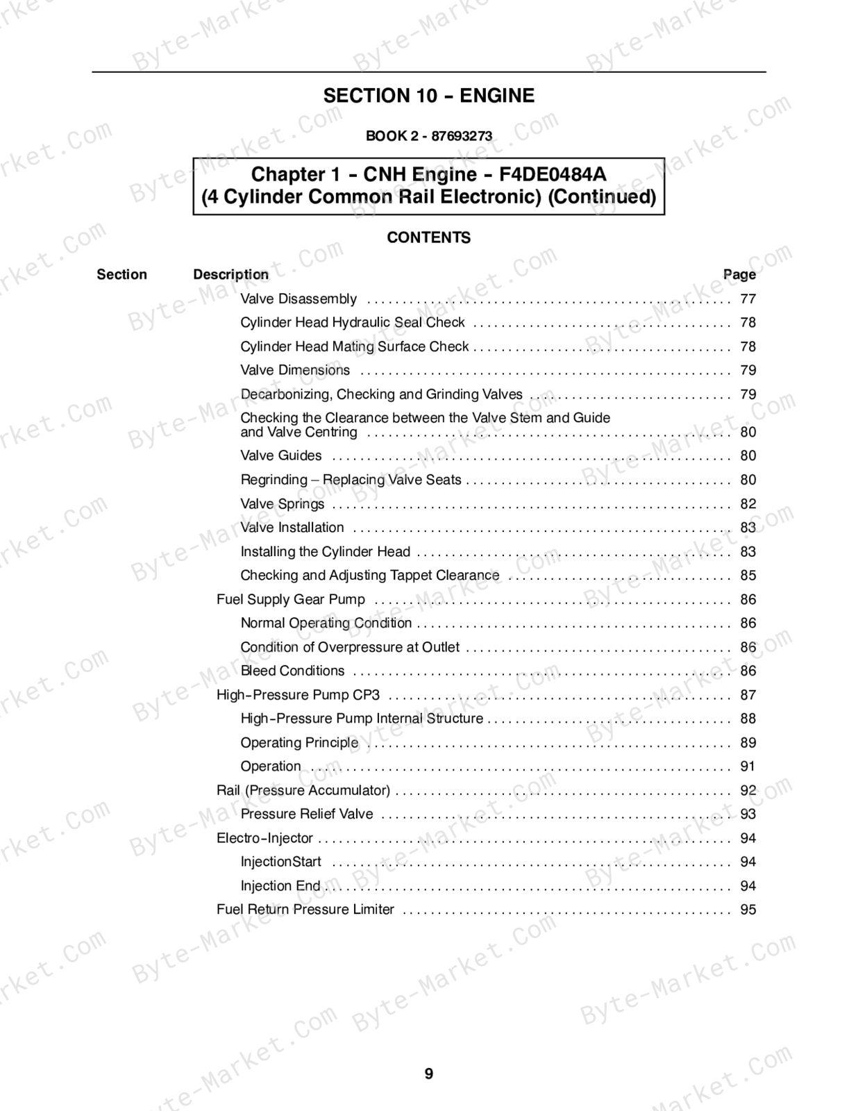
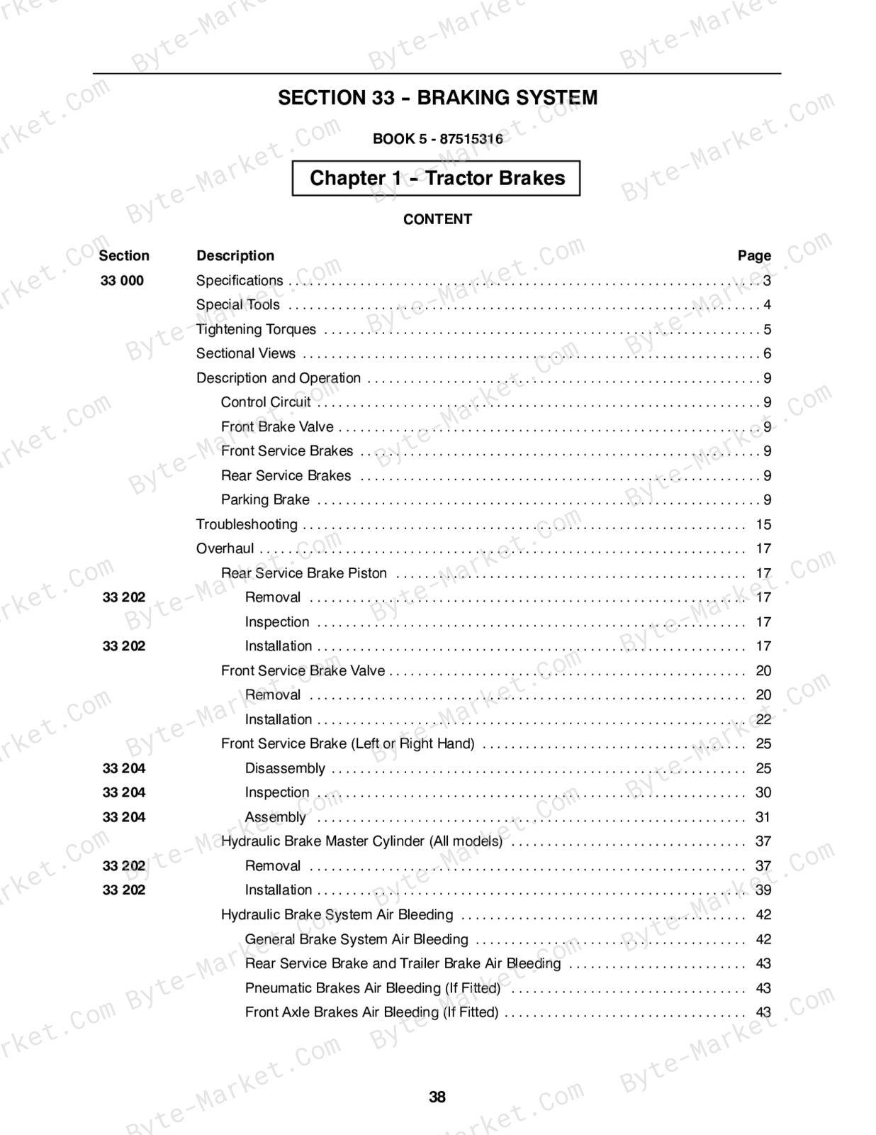
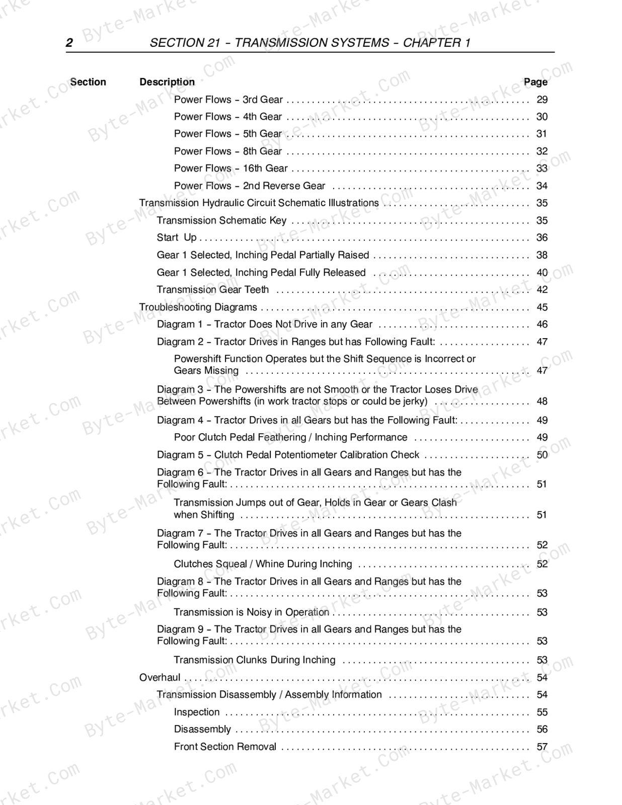
No questions found.