
About this manual
This English-language PDF service manual covers New Holland TVT 135, TVT 145, TVT 155, TVT 170, TVT 190 and TVT 195 tractors across Volumes 1–3. Its 2,396 pages bring together workshop procedures, system descriptions, troubleshooting information, electrical diagrams and component service instructions.
Volume 1 covers the engine, fuel system and electrical systems, including CAN Bus, ADIC, wiring harnesses, connectors and circuit diagrams. Volume 2 contains electrical fault codes. Volume 3 covers steering and front axles, transmission and rear-axle work, hydraulic systems, electronic hitch controls and air conditioning.
The manual is identified as Sva 6035448106. Separately identified TVT 195 chapters cover its engine, common-rail injection system and selected electrical topics. Individual chapters retain their own publication numbers and applicability.
Manual details
- Manual type
- Service Manual
- Publication number
- Sva 6035448106
- Contents revision
- Sva 6-92333, July 2006
- Format
- Language
- English
- Pages
- 2396
- Text search
- Available
- PDF navigation
- Interactive contents links and PDF bookmarks
- Document quality
- High — clear, readable text, illustrations and diagrams.
Applicability and limitations
- Check the chapter’s model and component designation before using its procedures.
- TVT 195 qualifications apply only to the chapters carrying that designation.
- The cabin chapter covers air conditioning; broader cab repair coverage is not established.
- July 2006 and Sva 6-92333 identify the contents revision, not the publication date and number of every chapter.
Systems and topics in this manual
Volume 1 — Engine
Engine workshop information includes a separately identified TVT 195 workshop manual.
Volume 1 — Fuel system
Injection-system descriptions include a separate common-rail system chapter for TVT 195.
Volume 1 — Electrical
Coverage includes CAN Bus basics, ADIC description and troubleshooting, functional diagrams, connectors, wiring harnesses, electrical and electronic components, and circuit diagrams. Selected chapters have separate TVT 195 versions.
Volume 2 — Electrical fault codes
Chapter 4011 contains fault-code information under publication 6-52632.
Volume 3 — Steering and front axles
Separate chapters cover the listed 20.25S and 20.29S independently suspended front axles, Carraro 20.25 and 20.25 FR, and independently suspended 20.25S, 20.25SI FR and 20.29SI/FR workshop information.
Volume 3 — Transmission and rear axle
Coverage includes transmission operation, system-hydraulic troubleshooting, cartridge removal and fitting, cartridge disassembly and assembly, rear-axle removal and fitting, rear-axle disassembly and assembly, and the rear-module parking interlock, four-wheel-drive clutch and bevel pinion.
Volume 3 — Hydraulics
Chapters cover CC-LS closed-center load-sensing hydraulics, the high-pressure hydraulic circuit, EDC electronic three-point hitch control and EHS auxiliary-control fault codes.
Volume 3 — Air conditioning
Air-conditioning information includes functional description and troubleshooting. The detailed chapter index also lists pressure testing, leak searches, refrigerant service and component removal and fitting.
Manual contents
Chapter identifiers and printed page references are retained below. Select the chapter that matches the model and component.
Volume 1 — Engine
- Workshop Manual (ref. 2002)
- Workshop Manual (TVT 195) (ref. 2002A)
Volume 1 — Fuel system
- Functional description Injection System (ref. 3001)
- Functional description Injection System - Common Rail System (TVT 195) (ref. 3001A)
Volume 1 — Electrical
- Functional description CAN Bus (Basics) (ref. 4002)
- Functional description and Troubleshooting – ADIC (ref. 4003)
- Function diagrams - Electrics (ref. 4008)
- Function diagrams - Electrics (TVT 195) (ref. 4008A)
- Connectors, Wiring Harnesses, Electrical and Electronic Components (ref. 4009)
- Connectors, Wiring Harnesses, Electrical and Electronic Components (TVT 195) (ref. 4009A)
- Circuit diagram (ref. 4010)
- Circuit diagram (TVT 195) (ref. 4010A)
Volume 2 — Electrical
- Fault codes (ref. 4011)
Volume 3 — Steering system
- Functional description, Troubleshooting and Settings — Front Axle with Independent Suspension 20.25S (ref. 5001) [publication 6-51450]
- Functional description, Troubleshooting and Settings — Front Axle with Independent Suspension 20.29S (ref. 5002) [publication 6-51500]
- Workshop Manual - Front Axle - Carraro 20.25, 20.25 FR (ref. 5005)
- Workshop Manual — Independently Suspended Front Axle 20.25S and 20.25SI FR (ref. 5006) [publication 6-51600]
- Workshop Manual - Independently Suspended Front Axle 20.29SI / FR (ref. 5007)
Volume 3 — Transmission
- Functional description Transmission (ref. 6001)
- Troubleshooting - System hydraulics (ref. 6002)
- Cartridge - Removing and Fitting (ref. 6005)
- Cartridge - Disassembling and Assembling (ref. 6006)
- Rear Axle - Removing and Fitting (ref. 6007)
- Rear Axle - Disassembling and Assembling (ref. 6008)
- Parking Interlock, 4-wheel Drive Clutch and Bevel Pinion (Rear Module) (ref. 6009)
Volume 3 — Hydraulic system
- Functional description CC-LS Hydraulic System (Closed Center-Load Sensing) (ref. 8001)
- Functional description and troubleshooting — High Pressure Hydraulic Circuit (ref. 8002) [publication 6-92610]
- Functional description and troubleshooting (Electronic 3-point hitch control system EDC) (ref. 8005) [publication 6-52100]
- Fault codes and fault description, EHS Auxiliary Control Units (ref. 8006)
Volume 3 — Cabin
- Functional description and troubleshooting Air Conditioning (ref. 9002)
Volume 2 — Electrical
- Fault codes (ref. 4011)
Volume 3 — Steering system
- Front Axle with Independent Suspension 20.25S (ref. 5001)
- Front Axle with Independent Suspension 20.29S (ref. 5002)
- Workshop Manual - Front Axle - Carraro 20.25, 20.25 FR (ref. 5005)
- Workshop Manual - Independently Suspended Front Axle 20.29SI / FR (ref. 5007)
- Workshop Manual - Independently Suspended Front Axle 20.25S and 20.25SI FR (ref. 5006)
Volume 3 — Transmission
- Functional description Transmission (ref. 6001)
- Troubleshooting - System hydraulics (ref. 6002)
- Cartridge - Removing and Fitting (ref. 6005)
- Cartridge - Disassembling and Assembling (ref. 6006)
- Rear Axle - Removing and Fitting (ref. 6007)
- Rear Axle - Disassembling and Assembling (ref. 6008)
- Parking Interlock, 4-wheel Drive Clutch and Bevel Pinion (Rear Module) (ref. 6009)
Volume 3 — Hydraulic system
- Functional description CC-LS Hydraulic System (Closed Center-Load Sensing) (ref. 8001)
- High Pressure Hydraulic Circuit (ref. 8002)
- (Electronic 3-point hitch control system EDC) (ref. 8005)
- Fault codes and fault description, EHS Auxiliary Control Units (ref. 8006)
Volume 3 — Cabin
- Functional description and troubleshooting Air Conditioning (ref. 9002)
2002 — Engine workshop manual
- SPECIAL TOOLS (ref. 5)
- FOR THE USER (ref. 7)
- Engine code and serial number (ref. 7)
- SAFETY REGULATIONS (ref. 8)
- ENGINE DATA (ref. 9)
- Lifting the engine (ref. 9)
- TECHNICAL DATA (ref. 10)
- Conformance with exhaust standards (ref. 10)
- Cylinder block (ref. 10)
- Cylinder liners (ref. 10)
- Cylinder head (ref. 10)
- Valves, rocker arms and push rods (ref. 11)
- Camshaft (ref. 12)
- Crankshaft (ref. 12)
- Flywheel (ref. 13)
- Gear drive, camshaft and injection pump (ref. 13)
- Con-rods (ref. 13)
- Pistons, piston rings and piston pins (ref. 14)
- Lubrication system (ref. 14)
- Lubrication oil pump (ref. 15)
- Thermostat (ref. 15)
- Coolant temperature indication and monitoring (signal from sensor B22) (ref. 15)
- Coolant pump (ref. 15)
- Schwitzer turbocharger S200 (ref. 15)
- Tightening torques (ref. 16)
- CONSTRUCTION (ref. 17)
- General (ref. 17)
- Cylinder block (ref. 17)
- Flywheel casing (ref. 17)
- Cylinder head (ref. 18)
- Valve mechanism (ref. 18)
- Crankshaft drive (ref. 20)
- Timing gears (ref. 21)
- Lubrication system (ref. 22)
- Cooling system (ref. 23)
- Fan (ref. 24)
- Intake/exhaust system (ref. 25)
2002 — Engine workshop manual
- ELECTRONIC ENGINE CONTROL SYSTEM – EEM2 (ref. 26)
- Layout (ref. 27)
- Signals (ref. 28)
- Function (ref. 28)
- JOB INSTRUCTIONS (ref. 29)
- 1. Cylinder block (ref. 29)
- A. Measuring the cylinder liner wear (ref. 29)
- B. Removing the cylinder liner (ref. 29)
- C. Checking the cylinder block (ref. 29)
- D. Replacing the camshaft bearing bush (ref. 29)
- E. Oversize bearing bushes for the camshaft (ref. 30)
- F. Fitting the plug at the rear camshaft end (ref. 31)
- G. Fitting the plug at the rear camshaft end after inserting an oversize bearing bush (ref. 31)
- H. Installing the oil dipstick tube (ref. 31)
- I. Fitting the cylinder liner (ref. 31)
- 2. Flywheel casing (ref. 33)
- A. Fitting the flywheel casing (ref. 33)
- B. Replacing the rear crankshaft sealing ring (ref. 33)
- 3. Cylinder head (ref. 34)
- A. Removing the cylinder head (ref. 34)
- B. Removing the valves (ref. 34)
- C. Checking the cylinder head (ref. 34)
- D. Replacing the valve guides (ref. 35)
- E. Machining the valve seat (ref. 36)
- F. Replacing the valve seat rings (ref. 36)
- G. Grinding the valves (ref. 36)
- H. Fitting the valves (ref. 37)
- I. Fitting the cylinder head (ref. 37)
- 4. Valve mechanism (ref. 38)
- A. Maintenance of the rocker arm system (ref. 38)
- B. Replacing the camshaft/camshaft gear wheel (ref. 38)
- C. Checking and adjusting the valve clearance (ref. 39)
- 5. Crankshaft (ref. 40)
- A. Removing the crankshaft (ref. 40)
- B. Checking the crankshaft (ref. 40)
- C. Replacing the crankshaft gear wheels (ref. 40)
- D. Fitting the crankshaft (ref. 41)
- E. Crankshaft hub (ref. 41)
- F. Replacing the crankshaft belt pulley and the vibration damper (ref. 42)
- G. Checking the rubber element in the vibration damper (ref. 42)
- 6. Pistons and con-rods (ref. 43)
- A. Removing the pistons together with the con-rods (ref. 43)
- B. Checking and replacing the con-rod bearings (ref. 43)
- C. Checking the con-rod (ref. 43)
- D. Checking and replacing the piston rings (ref. 44)
- E. Checking the pistons (ref. 45)
- F. Fitting the piston pin (ref. 45)
- G. Fitting the pistons and con-rods (ref. 45)
2002 — Engine workshop manual
- 7. Flywheel (ref. 46)
- A. Replacing the starter ring gear on the flywheel (ref. 46)
- B. Fitting the flywheel (ref. 46)
- 8. Timing mechanism (ref. 47)
- A. Removing the timing gear case (ref. 47)
- B. Replacing the intermediate gear wheel bearing bush (ref. 47)
- C. Fitting the timing gear case (ref. 48)
- 9. Lubrication system (ref. 50)
- A. Checking the oil pressure valve (ref. 50)
- B. Removing and checking the oil pump (ref. 50)
- C. Assembling and fitting the oil pump (ref. 50)
- D. Fitting the sump (ref. 51)
- E. Oil cooler (ref. 51)
- F. Piston cooling nozzles (ref. 52)
- G. Recommended lubrication oils (ref. 52)
- 10. Cooling system (ref. 53)
- A. Thermostat (ref. 53)
- B. Repairing the coolant pump (ref. 53)
- C. Coolant quality requirements (ref. 54)
- 11. Intake/exhaust system (ref. 55)
- A. Checking the air filter (ref. 55)
- B. Checking the intake/exhaust system (ref. 55)
- C. Checking the boost pressure (ref. 55)
- D. Checking the turbocharger (ref. 56)
- E. Fitting the turbocharger (ref. 57)
2002A — Engine workshop manual (TVT 195)
- SPECIAL TOOLS (ref. 7)
- TO THE USER (ref. 9)
- Engine code and serial number (ref. 9)
- SAFETY REGULATIONS (ref. 10)
- ENGINE DATA (ref. 11)
- Jumper lead starting and electrowelding (ref. 11)
- Lifting the engine (ref. 11)
- TECHNICAL DATA (ref. 12)
- Compliance with exhaust standards (ref. 12)
- Cylinder block (ref. 12)
- Cylinder liners (ref. 12)
- Cylinder head (ref. 12)
- Valves, rocker arms and push rods (ref. 13)
- Camshaft (ref. 14)
- Crankshaft (ref. 14)
- Flywheel (ref. 15)
- Gear drive - camshaft and high-pressure pump (ref. 15)
- Con-rods (ref. 15)
- Pistons, piston rings and piston pins (ref. 16)
- Lubrication system (ref. 16)
- Lubricating oil pump (ref. 17)
- Thermostat (ref. 17)
- Coolant temperature - display and monitoring (signal from sensor B22) (ref. 17)
- Coolant pump (ref. 17)
- Schwitzer turbocharger S200 (ref. 17)
- Tightening torques (ref. 18)
- CONSTRUCTION (ref. 19)
- GENERAL INFORMATION (ref. 19)
- Cylinder block (ref. 19)
- Flywheel casing (ref. 19)
- Cylinder head (ref. 20)
- Valve mechanism (ref. 20)
- Crank drive (ref. 21)
- Vibration absorber (ref. 22)
- Timing gears (ref. 23)
- Lubrication system (ref. 24)
- Cooling system (ref. 25)
- Fan (ref. 26)
- Intake / exhaust system (ref. 27)
- ELECTRONIC ENGINE CONTROL - EEM3 (ref. 29)
- Layout (ref. 30)
- Function (ref. 31)
- Signals (ref. 31)
2002A — Engine workshop manual (TVT 195)
- EEM3 in conjunction with the service tool (ref. 32)
- Error codes (ref. 32)
- Replacing the EEM3 box (ref. 36)
- WORK INSTRUCTIONS (ref. 37)
- 1. Cylinder block (ref. 37)
- A. Measuring wear on cylinder liners (ref. 37)
- B. Removing the cylinder liners (ref. 37)
- C. Checking the cylinder block (ref. 37)
- D. Replacing the camshaft bearing bush (ref. 38)
- E. Oversize bearing bushes for the camshaft (ref. 38)
- of camshaft (ref. 39)
- G. Adjusting the plug on the rear end of the camshaft after fitting an oversize bearing bush (ref. 39)
- H. Adjusting the cylinder liner (ref. 39)
- 2. Flywheel casing (ref. 41)
- A. Fitting the flywheel casing (ref. 41)
- B. Replacing the rear crankshaft sealing ring (ref. 41)
- 3. Cylinder head (ref. 42)
- A. Removing the cylinder head (ref. 42)
- B. Removing the valves (ref. 42)
- C. Checking the cylinder head (ref. 42)
- D. Replacing the valve guides (ref. 43)
- E. Machining the valve seat (ref. 44)
- F. Replacing the valve seat rings (ref. 44)
- G. Grinding the valves (ref. 44)
- H. Fitting the valves (ref. 45)
- I. Fitting the cylinder head (ref. 45)
- 4. Valve mechanism (ref. 46)
- A. Maintenance of the rocker arm system (ref. 46)
- B. Replacing the camshaft / the camshaft gear (ref. 46)
- C. Checking and adjusting valve clearance (ref. 47)
- 5. Crankshaft (ref. 48)
- A. Removing the crankshaft (ref. 48)
- g. Checking the crankshaft (ref. 48)
- C. Replacing the crankshaft gears (ref. 48)
- D. Fitting the crankshaft (ref. 49)
- E. Crankshaft hub (ref. 49)
- 6. Connecting rods and pistons (ref. 50)
- A. Removing the pistons together with the connecting rods (ref. 50)
- B. Checking and replacing the connecting rod bearings (ref. 50)
- C. Checking the connecting rod (ref. 50)
- D. Checking and replacing the piston rings (ref. 51)
- E. Checking the piston (ref. 52)
- F. Fitting the piston pin (ref. 52)
- G. Fitting pistons and connecting rods (ref. 52)
- 7. Flywheel (ref. 53)
- A. Replacing the starter ring gear on the flywheel (ref. 53)
- B. Fitting the flywheel (ref. 53)
- 8. Control mechanism (ref. 54)
- A. Removing the timing gear case (ref. 54)
2002A — Engine workshop manual (TVT 195)
- bearing bush (ref. 54)
- C. Fitting the timing gear case (ref. 55)
- 9. Lubrication system (ref. 57)
- A. Checking the oil pressure valve (ref. 57)
- B. Removing and checking the oil pump (ref. 57)
- C. Assembling and fitting the oil pump (ref. 57)
- D. Assembly of the oil sump (ref. 58)
- E. Oil cooler (ref. 58)
- F. Piston cooling nozzles (ref. 59)
- G. Recommended lubricants (ref. 59)
- 10. Cooling system (ref. 60)
- A. Thermostat (ref. 60)
- B. Repairs to coolant pump (ref. 60)
- C. Coolant quality requirements (ref. 61)
- 11. Air intake and exhaust system (ref. 62)
- A. Checking the air filter (ref. 62)
- B. Checking the air intake system and exhaust system (ref. 62)
- D. Checking the turbocharger (ref. 63)
- E. Assembly of the turbocharger (ref. 64)
3001 — Injection system: functional description
- SPECIAL TOOLS (ref. 5)
- GENERAL INFORMATION (ref. 7)
- SAFETY REGULATIONS (ref. 7)
- TECHNICAL DATA (ref. 8)
- Injection pump (ref. 8)
- Type of pump ( related to engine type) (ref. 8)
- Sequence of injection (ref. 8)
- Fuel supply (ref. 8)
- Fuel filters (ref. 8)
- Injectors and Nozzles (ref. 8)
- Tightening torques (ref. 8)
- FUEL SYSTEM (ref. 9)
- Function (ref. 10)
- Safety measures (ref. 10)
- Electronically controlled fuel injection system (ref. 11)
- Solenoid-Valve-Controlled Axial-Piston Distributor Pump (ref. 12)
- General (ref. 13)
- Parameters affecting the injection timing (ref. 13)
- Parameters affecting the maximum quantity of fuel injected (ref. 13)
- Emergency operation and emergency engine stop (ref. 13)
- Signal „engine speed“ faulty: (ref. 13)
- Idle speed (ref. 13)
- Electronic control (ref. 14)
- Injection Pump - Operating Principle (ref. 15)
- Operating Principle (ref. 16)
- IAT Sensor - Commencement of Delivery and Pump Speed (ref. 17)
- Bleeding the fuel system (ref. 18)
- General (ref. 18)
- Automatic bleeding during operation (ref. 18)
- Bleeding after changing the fuel filter (ref. 18)
- Bleeding after fuel has been used up (ref. 18)
- Bleeding after a new or an overhauled injection pump has been fitted (ref. 18)
- Fuel feed pressure (ref. 19)
- Testing the fuel feed pressure (ref. 19)
- Removal of the fuel injection pump (ref. 20)
- Fitting the fuel injection pump (ref. 21)
- Static pump timing (ref. 21)
- Updating pump serial numbering in EEM (ref. 21)
- Final jobs (ref. 21)
- Injectors and nozzles (ref. 22)
- Removing the injectors (ref. 22)
- Checking the nozzles (ref. 22)
- Overhauling injectors (ref. 23)
- Fitting the injectors (ref. 23)
- Assembly of the injection lines (ref. 23)
- Fuel quality requirements (ref. 24)
- (RME = Rape oil-Methyl-Ester Bio - Fuel) (ref. 24)
- Service intervals (ref. 24)
3001A — Common-rail injection system (TVT 195)
- SPECIAL TOOLS (ref. 5)
- GENERAL (ref. 7)
- SAFETY REGULATIONS (ref. 7)
- TECHNICAL DATA (ref. 8)
- High-pressure pump (ref. 8)
- Injectors (ref. 8)
- Fuel (ref. 8)
- Fuel filter (ref. 8)
- Tightening torques (ref. 8)
- JUMPER LEAD STARTING AND ELECTROWELDING (ref. 8)
- FUEL SYSTEM (ref. 9)
- Function (ref. 10)
- Safety equipment (ref. 11)
- Diagram - Electronically controlled injection system (ref. 12)
- Venting the fuel system (ref. 13)
- Checking the fuel delivery pressure (ref. 13)
- Checking the injectors (ref. 14)
- Removing the injectors (ref. 14)
- Assembly of injectors (ref. 14)
- High-pressure pump (ref. 15)
- Removing the high-pressure pump (ref. 15)
- Assembly of high-pressure pump (ref. 16)
- Final work (ref. 16)
- Fuel quality requirements (ref. 17)
4002 — CAN Bus basics
- INTRODUCTION (ref. 5)
- DIGITAL TECHNOLOGY (ref. 6)
- Advantage of digital message transmission (ref. 6)
- Ranges for 1 and 0 (ref. 7)
- Parallel Data Transmission (ref. 8)
- Serial Data Transmission (ref. 8)
- DATA BUS (ref. 9)
- Function (ref. 10)
- Can bus line (ref. 11)
- Can high – Can low (ref. 12)
- CAN High Speed Signal Level (ref. 13)
- Topology (ref. 14)
- Data Transmission (ref. 14)
- DATA PROTOCOL (ref. 15)
- Structure of the CAN Data Frame – Standard Identifier (11 bits) CAN V2.0A (ref. 15)
- Structure of the CAN Data Frame – Standard Identifier (29 bits) CAN V2.0B (ref. 17)
- Structure of the CAN Remote Frames Identifier (ref. 19)
- ERROR DETECTION (ref. 20)
- Mechanisms on the Data Frame level (ref. 20)
- Mechanisms of the Bit Level (ref. 20)
- TROUBLESHOOTING (ref. 21)
- Interrupting the Transmission (ref. 21)
- Resumption of the Transmission (ref. 21)
- Realtime Transmission (ref. 21)
- TRANSMISSION SPEED (ref. 22)
- TELEGRAM LENGTH (ref. 23)
- CENTRAL GATEWAY (ref. 25)
- SERVICE TOOL (ref. 25)
4003 — ADIC: functional description and troubleshooting
- TABLE OF CONTENTS (ref. 3)
- SPECIAL TOOLS (ref. 5)
- GENERAL DESCRIPTION (ref. 6)
- GENERAL NOTES (ref. 7)
- Handling plug-in connections (ref. 7)
- Regulations for using jumper cables for starting (ref. 7)
- Regulations for carrying out electro-welding work on the tractor or on an implement (ref. 7)
- ANALOG AND DIGITAL DISPLAYS (ref. 8)
- WARNING AND INDICATOR LAMPS (ref. 9)
- ANALOG DISPLAY INSTRUMENTS (ref. 10)
- Engine speed display (ref. 10)
- Coolant temperature display (ref. 10)
- Fuel level indicator (ref. 10)
- DIGITAL DISPLAY INSTRUMENTS (ref. 11)
- Display 1 (ref. 11)
- Display 2 (ref. 11)
- Display 3 (ref. 11)
- ADJUSTMENT BUTTONS (ref. 12)
- DMD (DOT MATRIX DISPLAY) (ref. 13)
- Warnings (ref. 13)
- Information (ref. 13)
- Service (ref. 14)
- KEYPADS (ref. 15)
- Service interval key (ref. 15)
- Odometer key (ref. 15)
- Hectare counter key (ref. 16)
- Hectare performance / hour key (ref. 16)
- Menu up scroll key (ref. 16)
- Enter / Save key (ref. 16)
- Menu down scroll key (ref. 16)
- Escape key without saving (ref. 16)
- Key for displaying 3-point hitch position front / rear (ref. 17)
- Key for displaying PTO shaft speed front / rear (ref. 17)
- Wheel slip key (ref. 17)
- Battery voltage key (ref. 17)
- Engine operating hours key (ref. 17)
- Key for tractor RESET (ref. 18)
- Key for compressed air trailer braking system (ref. 18)
- Changeover key for driving strategy and speed range display (ref. 18)
4003 — ADIC: functional description and troubleshooting
- MENU SETTINGS (ref. 19)
- Setup menu 1 (ref. 19)
- Setup menu 2 (ref. 21)
- Plugs on the ADIC (ref. 23)
- TROUBLESHOOTING USING THE DIAGNOSTIC SYSTEM (ref. 24)
- TEST VALUES FOR SPEED DISPLAYS (ref. 29)
- TEST VALUES FOR ANALOG DISPLAYS AND WARNING (ref. 29)
4008 — Electrical functional diagrams
- GENERAL DESCRIPTION (ref. 5)
- Abbreviations (ref. 5)
- Supply voltages (ref. 5)
- General advise: (ref. 5)
- A27 CAN module and A28 Plug module ---> DBD094270 (ref. 6)
- A30 ARU print DBD094271 ---> (ref. 6)
- FUNCTIONAL SCHEMATIC DIAGRAM FOR ADIC (ref. 7)
- FUNCTIONAL SCHEMATIC DIAGRAM FOR EEM2 (ref. 9)
- FUNCTIONAL SCHEMATIC DIAGRAM FOR FMGR - SGR (ref. 11)
- FUNCTIONAL SCHEMATIC DIAGRAM FOR FMGR REVERSING FACILITY (ref. 15)
- FUNCTIONAL SCHEMATIC DIAGRAM FOR ECCU2 (ref. 17)
- FUNCTIONAL SCHEMATIC DIAGRAM FOR EDC (ref. 21)
- FUNCTIONAL SCHEMATIC DIAGRAM FOR REMOTE CONTROL VALVES (ref. 25)
- FUNCTIONAL SCHEMATIC DIAGRAM FOR REMOTE CONTROL VALVES - ADDITIONAL FUNCTIONS (ref. 27)
- FUNCTIONAL SCHEMATIC DIAGRAM FOR FRONT AXLE WITH INDEPENDENT SUSPENSION (ref. 29)
- FUNCTIONAL SCHEMATIC DIAGRAM FOR CAN BUS (ref. 31)
- FUNCTIONAL SCHEMATIC DIAGRAM FOR ISO BUS (ref. 33)
4008A — Electrical functional diagrams (TVT 195)
- GENERAL DESCRIPTION (ref. 5)
- Abbreviations (ref. 5)
- Supply voltages (ref. 5)
- FUNCTIONAL SCHEMATIC DIAGRAM FOR ADIC (ref. 7)
- FUNCTIONAL SCHEMATIC DIAGRAM FOR EEM3 (ref. 9)
- FUNCTIONAL SCHEMATIC DIAGRAM FOR FMGR - SGR (ref. 13)
- FUNCTIONAL SCHEMATIC DIAGRAM FOR FMGR REVERSING FACILITY (ref. 17)
- FUNCTIONAL SCHEMATIC DIAGRAM FOR ECCU2 (ref. 19)
- FUNCTIONAL SCHEMATIC DIAGRAM FOR EDC (ref. 23)
- FUNCTIONAL SCHEMATIC DIAGRAM FOR REMOTE CONTROL VALVES (ref. 27)
- FUNCTIONAL SCHEMATIC DIAGRAM FOR REMOTE CONTROL VALVES - ADDITIONAL FUNCTIONS (ref. 29)
- FUNCTIONAL SCHEMATIC DIAGRAM FOR FRONT AXLE WITH INDEPENDENT SUSPENSION (ref. 31)
- FUNCTIONAL SCHEMATIC DIAGRAM FOR CAN BUS (ref. 33)
- FUNCTIONAL SCHEMATIC DIAGRAM FOR ISO BUS (ref. 35)
4009 — Connectors, wiring harnesses, electrical and electronic components
- WIRING HARNESS CODING (ref. 7)
- MAIN CONNECTOR (ref. 8)
- CONTROLLER AND PRINTS (ref. 11)
- FLYING FUSES AND RELAYS (ref. 13)
- IDENTIFICATION AND COLOUR CODING OF CABLES (ref. 14)
- Abbreviations (ref. 15)
- ENGINE BONNET WIRING HARNESS (ref. 16)
- ENGINE WIRING HARNESS (ref. 20)
- 1. Additional line 2. alternator, Magneton 95 A (ref. 33)
- 2. Additional line for 7-pin trailer socket and power socket, front (ref. 33)
- 3. Additional line for angle of rotation sensor, front (ref. 33)
- 4. Additional line for speed sensor, PTO front (ref. 33)
- 5. Additional line for fuel-water separator sensor (ref. 33)
- 6. Additional line for reversible fan (ref. 33)
- 7. Additional line for battery ground (ref. 34)
- 8. Additional line for battery starter + (ref. 34)
- 9. Additional line for electrical battery main switch + (ref. 34)
- 10. Additional line for electrical starter main switch + (ref. 34)
- 11. Additional line for Magneton alternator (ref. 35)
- 12. Additional line for Denso alternator (ref. 35)
- 13. Additional line for main switch battery + (ref. 35)
- 14. Additional line for main switch starter + (ref. 35)
- INSTRUMENTS WIRING HARNESS (ref. 42)
- 1. Additional line 2. alternator (ref. 53)
- 2. Additional line for electrical battery main switch (ref. 53)
- 3. Additional line for single wheel, sprung front axle (ref. 53)
- 4. Additional line for Webasto heater (ref. 53)
- CAB WIRING HARNESS ON RIGHT (ref. 60)
- 1. Additional line for bridge, Molex 2-pin (ref. 76)
- 2. Additional line for mobile phone precaution (ref. 76)
- 3. Additional line for lifting/pressure (ref. 76)
- 4. Additional line for hydraulic trailer brake (ref. 77)
- 5. Additional line for hydraulic trailer brake solenoid valve (ref. 77)
- 6. Additional line for standard signal socket T1 (ref. 77)
- 7. Additional line for standard signal socket T2 (ref. 77)
- 8. Additional line for radar sensor (ref. 77)
- 9. Additional line for power socket, additional monitor, cab (ref. 77)
- 10. Additional line for additional side marker lights, wide tyres (ref. 77)
4009 — Connectors, wiring harnesses, electrical and electronic components
- CONTROL PANEL WIRING HARNESS, RIGHT (ref. 84)
- 1. Additional line for potentiometer for nominal value and EDC lighting (ref. 91)
- 2. Additional line for potentiometer for lifting limitation (ref. 91)
- 3. Additional line for potentiometer for mixing (ref. 91)
- 4. Additional line for potentiometer for lowering speed (ref. 91)
- 5. Additional line for potentiometer for slip control (ref. 91)
- 6. Additional line for potentiometer for limit load (ref. 91)
- 7. Additional line for potentiometer for panel lighting (ref. 91)
- CARTRIDGE WIRING HARNESS (ref. 94)
- 1. Additional line for Linde electronics - hydrostat (ref. 99)
- CAB WIRING HARNESS ON LEFT (ref. 101)
- 1. Additional line 2. power socket, rear (ref. 105)
- 2. Additional line for trailer socket, 7-pin, front (ref. 105)
- ROOF SUPPLY WIRING HARNESS (ref. 107)
- ROOF WIRING HARNESS (ref. 110)
- 1. Additional line for turn signal side marker lights and worklights, front left and right (ref. 120)
- 2. Additional line for side marker lights, front left and right (wide tyres) (ref. 121)
- 3. Additional line for side marker lights and additional light, front left and right (ref. 121)
- 4. Additional line for auxiliary headlights and worklights (ref. 121)
- 5. Additional line for number plate lighting (ref. 121)
- 6. Additional line for all-round light bar (ref. 121)
- 7. Additional line for 6 worklights (ref. 123)
- 8. Additional line for electrical mirror adjustment and heating (ref. 123)
- 9. Additional line for air conditioning system (ref. 123)
- 10. Additional line for solenoid, all-round light, standard socket (ref. 123)
- 11. Additional line for all-round light (ref. 123)
- 12. Additional line for wiper, hinged windscreen, front (ref. 123)
- 13. Additional line for blower ventilation (ref. 125)
- 14. Additional line for front heated windscreen (ref. 125)
- 15. Additional line for rear heated windscreen (ref. 125)
- 16. Additional line for mirror heating (ref. 125)
- 17. Additional Xenon worklight (ref. 125)
- ELECTRICAL REMOTE CONTROL VALVES WIRING HARNESS (ref. 144)
- 1. Additional line for external button, powerlift, front (ref. 147)
- 2. Additional line for external button for front remote control valves (ref. 147)
- REVERSE TRAVEL EQUIPMENT WIRING HARNESS (ref. 150)
- 1. Additional line for wash tank extension (ref. 157)
- 2. Additional line for rear wiper extension (ref. 157)
- ISO BUS WIRING HARNESS (ref. 160)
4009 — Connectors, wiring harnesses, electrical and electronic components
- COMPONENTS (ref. 167)
- Armrest (ref. 167)
- Central print A12 (Würth) (ref. 168)
- Central print A12 (Berifors) (ref. 170)
- Roof print A13 (Würth) (ref. 172)
- Roof print A13 (Berifors) (ref. 173)
- Engine print A14 (Würth) (ref. 174)
- Engine print A14 (Berifors) (ref. 175)
- EDC print A16 (Würth) (ref. 176)
- EDC print A16 (Berifors) (ref. 177)
- Can module A27 and plug module A28 to DBD094270 (ref. 178)
- Print ARU A30 as of DBD094271 (ref. 179)
- Relays (ref. 180)
- Components - engine and fuel system (ref. 182)
- Components - transmission (ref. 186)
- Components - differential lock (ref. 189)
- Components - front PTO (ref. 190)
- Components - rear PTO (ref. 190)
- Components - individual wheel, sprung front axle (ref. 191)
- Components - brake (ref. 192)
- Components - reverse travel equipment (ref. 194)
- Components - hydraulics (ref. 196)
- Components - EDC (ref. 198)
- Components - front powerlift (ref. 199)
- Components - air conditioning system (ref. 200)
- Components - cab (ref. 203)
4009A — Connectors, wiring harnesses, electrical and electronic components (TVT 195)
- WIRING HARNESS DESIGNATION (ref. 7)
- MAIN CONNECTOR (ref. 8)
- CONTROLLER AND PRINT´S (ref. 11)
- FLYING FUSES AND RELAYS (ref. 13)
- SOCKETS (ref. 14)
- DESIGNATION AND COLOUR CODING OF CABLESEL (ref. 16)
- Abbreviations (ref. 17)
- ENGINE HOOD WIRING HARNESS (ref. 18)
- INJECTORS - ENGINE WIRING HARNESS (ref. 21)
- ENGINE WIRING HARNESS (ref. 24)
- 1. Additional line for 2nd Magneton alternator 95 A (ref. 37)
- 2. Additional line for 7-pin trailer socket and power socket at front (ref. 37)
- 3. Additional line for angle of rotation sensor at front (ref. 37)
- 4. Additional line for speed sensor for front PTO (ref. 37)
- 5. Additional line for reverse fan (ref. 37)
- 6. Additional line for battery - ground (ref. 38)
- 7. Additional line for battery - starter + (ref. 38)
- 8. Additional line for electrical main switch - battery + (ref. 38)
- 9. Additional line for electrical main switch - starter + (ref. 38)
- 10. Additional line for main switch - battery + (ref. 39)
- 11. Additional line for main switch - starter + (ref. 39)
- SENSORS - ENGINE WIRING HARNESS (ref. 47)
- INSTRUMENTS WIRING HARNESS (ref. 52)
- 1. Additional line for 2nd alternator (ref. 63)
- 2. Additional line for independent suspension, sprung front axle (ref. 63)
- RIGHT CAB WIRING HARNESS (ref. 68)
- 1. Additional line for Molex bridge 2-pin (ref. 84)
- 2. Additional line for mobile phone precaution (ref. 84)
- 3. Additional line for raise/lower (ref. 84)
- 4. Additional line for hydraulic trailer brake (ref. 85)
- 5. Additional line for hydraulic trailer brake solenoid valve (ref. 85)
- 6. Additional line for standard signal socket T1 (ref. 85)
- 7. Additional line for standard signal socket T2 (ref. 85)
- 8. Additional line for radar sensor (ref. 85)
- 9. Additional line for power socket, additional monitor for cab (ref. 85)
- 10. Additional line for additional marker light, wide tyres (ref. 85)
4009A — Connectors, wiring harnesses, electrical and electronic components (TVT 195)
- CONTROL PANEL, RIGHT WIRING HARNESS (ref. 92)
- 1. Additional line for nominal value and EDC lighting potentiometer (ref. 99)
- 2. Additional line for lifting limitation potentiometer (ref. 99)
- 3. Additional line for mixing potentiometer (ref. 99)
- 4. Additional line for lowering speed potentiometer (ref. 99)
- 5. Additional line for slip control potentiometer (ref. 99)
- 6. Additional line for limit load potentiometer (ref. 99)
- 7. Additional line for potentiometer for panel lighting (ref. 99)
- CARTRIDGE WIRING HARNESS (ref. 102)
- 1. Plug connection for Linde electronics - hydrostat (ref. 107)
- CAB ON LEFT WIRING HARNESS (ref. 109)
- 1. Additional line for 2nd rear power socket (ref. 113)
- ROOF SUPPLY WIRING HARNESS (ref. 115)
- ROOF WIRING HARNESS (ref. 118)
- 1. Additional line for front left and right turn signal / side marker light and work lamps (ref. 128)
- 2. Additional line for front left and right side marker light (wide tyres) (ref. 129)
- 3. Additional line for front left and right side marker light and additional light (ref. 129)
- 4. Additional line for auxiliary headlight and work lamp (ref. 129)
- 5. Additional line for licence plate lights (ref. 129)
- 6. Additional line for all-round light bar (ref. 129)
- 7. Additional line for 6 work lamps (ref. 131)
- 8. Additional line for electrical mirror adjustment and heating (ref. 131)
- 9. Additional line for air conditioning system (ref. 131)
- 10. Additional line for solenoid, all-round light, standard socket (ref. 131)
- 11. Additional line for all-round light (ref. 131)
- 12. Additional line for wiper, hinged windscreen, front (ref. 131)
- 13. Additional line for blower ventilation (ref. 133)
- 14. Additional line for front heated windscreen (ref. 133)
- 15. Additional line for rear heated windscreen (ref. 133)
- 16. Additional line for mirror heating (ref. 133)
- 17. Additional line for Xenon work lamp (ref. 133)
- ELECTRICAL REMOTE CONTROL VALVES WIRING HARNESS (ref. 152)
- 1. Additional line for external button, powerlift, front (ref. 155)
- 2. Additional line for external button for front remote control valves (ref. 155)
- REVERSE TRAVEL EQUIPMENT WIRING HARNESS (ref. 158)
- 1. Additional line for wash tank extension (ref. 165)
- 2. Additional line for rear wiper extension (ref. 165)
- ISO BUS WIRING HARNESS (ref. 168)
4009A — Connectors, wiring harnesses, electrical and electronic components (TVT 195)
- ARMREST WIRING HARNESS (ref. 174)
- 1. Additional line for multicontroller (ref. 178)
- 2. Additional line for AUX5 button (ref. 178)
- 3. Additional line for rapid retraction button (ref. 179)
- 4. Additional line for manual accelerator slider (ref. 179)
- 5. Additional line for AUX control lever (ref. 179)
- 6. Additional line for AUX joystick (ref. 179)
- 7. Additional line for potentiometers AUX1 and 2 (ref. 179)
- 8. Additional line for potentiometers AUX3 and 4 (ref. 179)
- 9. Additional line for potentiometer AUX5 (ref. 179)
- 10. Additional line for lighting (ref. 179)
- 11. Additional line for EDC stop button (ref. 179)
- 12. Additional line for shift button (floating position) (ref. 179)
- COMPONENTS (ref. 185)
- Armrest (ref. 185)
- Central print A12 (ref. 186)
- Engine print A14 (ref. 188)
- Roof print A13 (ref. 190)
- EDC print A16 (ref. 191)
- Print ARU A30 (ref. 192)
- Relay (ref. 193)
- Engine and fuel system components (ref. 195)
- Transmission components (ref. 200)
- Differential lock components (ref. 203)
- Front PTO shaft components (ref. 204)
- Rear PTO shaft components (ref. 204)
- Individual wheel, sprung front axle components (ref. 205)
- Brake components (ref. 206)
- Reversing facility components (ref. 208)
- Hydraulics components (ref. 210)
- EDC components (ref. 212)
- Front power lift components (ref. 213)
- Air conditioning system components (ref. 214)
- Cab components (ref. 216)
4010 — Circuit diagram
- 4 + 2 front work lamps (ref. 31)
- Additional front left light (ref. 27)
- Additional front right light (ref. 27)
- Additional rear left light (ref. 27)
- Additional rear right light (ref. 27)
- ADIC (ref. 53, 55, 57)
- Air conditioning (ref. 45)
- Air cushion seat (ref. 47)
- All-round light carrier (ref. 39)
- All-round lights (can be plugged in) (ref. 37)
- All-round lights (magnetic) (ref. 41)
- Alternator Denso (ref. 11)
- Alternator Magneton (ref. 7)
- Alternator Magneton (2nd alternator) (ref. 9)
- Angle of rotation sensor, coupling (ref. 75)
- reverse travel equipment (ref. 77)
- Angle of rotation sensor, power lift, front (ref. 97)
- Angle of rotation sensor, power lift, rear (ref. 65, 67)
- Angled wiper, front (ref. 49)
- Angled wiper, rear (ref. 49)
- Armrest (ref. 69)
- Armrest, electronics (ref. 107, 109, 111, 113, 115)
- ASR with radar sensor (ref. 51)
- AUX valves (ref. 105)
- Auxiliary headlight and 4 work lamps (ref. 29)
- BB light, left (ref. 23, 25)
- BB light, left and right (ref. 27)
- BB light, right (ref. 23, 25)
- Blower (heating) (ref. 21)
- Blower (roof) (ref. 47)
- Brake light (ref. 17)
- Brake light for reverse travel equipment (ref. 19)
- Button, AUX 5 (ref. 111)
- Button, EDC - stop and lighting (ref. 111)
- Button, raise/lower EDC (ref. 71)
- Button, rapid retraction (ref. 111)
- CAN BUS (ref. 99, 101, 103)
- Cigarette lighter with socket on right, 2-pin (ref. 61, 63)
- Clutch switch 80% (ref. 75)
- Clutch switch 80% for reverse travel equipment (ref. 77)
- Control handle for AUX (ref. 109)
- Control signal (ref. 69)
- D supply+ (ref. 15)
- Display for reverse travel equipment (ref. 87)
- Door contact switch (ref. 35)
- Doorway lights (ref. 35)
- EDC signal 50% (ref. 73)
- EDC with raise/lower (ref. 67)
- EDC without raise/lower (ref. 65)
- EEM2 - box with sensors and PCU (ref. 15)
- Electrical mirror adjustment (ref. 37, 39, 41)
- External button, AUX, front (ref. 97)
- External button, EDC (ref. 71)
- External button, power lift, front (ref. 97)
- Filter heating (preparation) (ref. 53, 55)
- Front PTO shaft (ref. 91)
- Fuel delivery pump (ref. 7, 9, 11)
- Gearbox electronics (ref. 85, 87)
- Headlight (ref. 29)
- Heated windscreen, front (ref. 43)
- Heated windscreen, rear (ref. 43)
- Heating flange (ref. 7, 9, 11)
- Heating flange, fuel delivery pump (ref. 13)
- Heating valve for hydraulic oil (ref. 105)
- Horn (ref. 49)
- Horn for reverse travel equipment (ref. 79)
- ICU performance monitor (ref. 85, 87)
- Indicator lights, EDC (ref. 73)
- Interface, wiring harness, cab, right (ref. 107)
- Interior light (ref. 35)
- ISO-BUS (ref. 117)
- Joystick with button (ref. 109)
- Licence plate lights, roof (ref. 35)
- Limit load potentiometer (ref. 75)
- LIMP HOME plug connection (ref. 85, 87)
- Low beam, high beam (ref. 29)
- Magneton alternator (ref. 13)
- Manual accelerator slider (ref. 109)
- Mirror heating (ref. 37, 39, 41)
- Multicontroller II (ref. 115)
4010 — Circuit diagram
- Parallel wipers, front (ref. 49)
- Parking interlock switch (ref. 75, 79)
- Potentiometer, accelerator pedal (ref. 75)
- reverse travel equipment (ref. 77)
- Potentiometer, AUX remote control valves (ref. 113)
- Potentiometer, EDC (ref. 73)
- travel equipment (ref. 79)
- Power lift, front, management (ref. 97)
- Power lift, front, raise/lower (ref. 69)
- Power sensors (ref. 65, 67)
- Power socket (ref. 51)
- Power socket 1, rear (ref. 51)
- Power socket 2, rear (preparation) (ref. 51)
- Power socket, front (ref. 51)
- Power supply and starter (ref. 7, 9, 11)
- Power supply, electrical battery main switch (ref. 13)
- Radio preparation (ref. 43)
- Rear PTO shaft (ref. 91)
- Reserve (ref. 111)
- Reserve central print (ref. 17, 19)
- Reserve, EDC print (ref. 61, 63)
- Reverse fan (ref. 17, 19)
- SBB light, left (ref. 23, 25, 27)
- SBB light, right (ref. 23, 25, 27)
- Seat switch for reverse travel equipment (ref. 79)
- Sensors, cartridge switch (ref. 89)
- Shuttle lever (ref. 85, 87)
- Socket, diagnosis ADIC (ref. 57)
- Socket, front (ref. 51)
- Socket, mobile phone, left (ref. 61)
- reverse travel equipment (ref. 63)
- Socket, rear (trailer) (ref. 51)
- Socket, standard signal (ref. 57)
- Solenoid valves, brake oil cooling (ref. 81, 83)
- Solenoid valves, cartridge (ref. 89)
- Solenoid valves, raising, lowering (ref. 65, 67)
- Speed sensors, cartridge (ref. 89)
- Speed sensors, PTO, front and rear (ref. 59)
- Speed signal (ref. 71)
- Spot light (ref. 37, 39, 41)
- Spring-mounted front axle (ref. 93, 95)
- Starter (ref. 13)
- Steering column switch (ref. 49)
- Supply for ADIC (ref. 53)
- Supply for ADIC, ISO BUS (ref. 55)
- Supply, control panel, right (ref. 61, 63)
- Supply, ECCU2 (ref. 93)
- Supply, ECCU2 for ISO BUS (ref. 95)
- Supply, EDC box (ref. 65, 67)
- Supply, EEM2 box (ref. 15)
- Supply, FMGR (ref. 75, 77)
- Supply, potential 15/1 (ref. 7, 9, 11, 13)
- Supply, potential 15/1 seat, trailer brake (ref. 47)
- Supply, roof (ref. 43)
- management (ref. 81)
- management for reverse travel equipment (ref. 83)
- Switch for engine back pressure brake (ref. 75)
- handbrake for reverse travel equipment (ref. 79)
- Switch for handbrake, seat switch (ref. 75)
- Switch for HTS (ref. 59)
- Switch for reducing speed (ref. 59)
- Switch for speed ranges, manual mode (ref. 81)
- reverse travel equipment (ref. 83)
- Trailer brake (ref. 21)
- Warning light system (ref. 23, 27)
- electrical main battery switch (ref. 25)
- WEBASTO engine preheating (ref. 35)
- Windscreen washing system, front (ref. 49)
- Windscreen washing system, rear (ref. 49)
- Work lamp at rear inside (ref. 31)
- Work lamp at rear outside (ref. 31)
- Work lamp, BB light (ref. 31)
- Work lamp, engine hood (ref. 35)
- Work lamp, fender (ref. 29)
- Work lamp, rear, XENON (ref. 33)
4010A — Circuit diagram (TVT 195)
- Additional marker light, front left (ref. 25)
- Additional marker light, front right (ref. 25)
- Additional marker light, rear left (ref. 25)
- Additional marker light, rear right (ref. 25)
- ADIC (ref. 51, 53, 55)
- Air conditioning (ref. 43)
- Air cushion seat (ref. 45)
- All-round light carrier 45 (ref. 37)
- All-round lights (can be plugged in) (ref. 35)
- All-round lights (magnetic) (ref. 39)
- Angle of rotation sensor, coupling (ref. 73)
- reverse travel equipment (ref. 75)
- Angle of rotation sensor, power lift, front (ref. 95)
- Angle of rotation sensor, power lift, rear (ref. 63, 65)
- Angled wiper, front (ref. 47)
- Angled wiper, rear (ref. 47)
- Armrest (ref. 67)
- Armrest, electronics (ref. 105, 107, 109, 111, 113)
- ASR with radar sensor (ref. 49)
- AUX valves (ref. 103)
- AUX5 button (ref. 109)
- Auxiliary headlight and 4 work lamps (ref. 27)
- BB light, left (ref. 23)
- BB light, left and right (ref. 25)
- BB light, right (ref. 23)
- Blower (roof) (ref. 45)
- Bosch and Magneton generator (ref. 9)
- Bosch generator (ref. 7, 11)
- Brake light (ref. 17)
- Brake light for reverse travel equipment (ref. 19)
- Button, EDC - stop and lighting (ref. 109)
- Button, rapid retraction (ref. 109)
- CAN BUS (ref. 97, 99, 101)
- Cigarette lighter with socket on right, 2-pin (ref. 59, 61)
- Clutch switch 80% (ref. 73)
- reverse travel equipment (ref. 75)
- Control handle for AUX (ref. 107)
- D supply+ (ref. 13)
- Display for reverse travel equipment (ref. 85)
- Door contact switch (ref. 33)
- Doorway lights (ref. 33)
- EDC signal 50% (ref. 71)
- EDC with raise/lower (ref. 65)
- EDC without raise/lower (ref. 63)
- EEM3 box supply (ref. 13)
- EEM3 box with sensors and injectors (ref. 15)
- Electrical mirror adjustment (ref. 35, 37, 39)
- External button, AUX, front (ref. 95)
- External button, power lift, front (ref. 95)
- Filter heating (preparation) (ref. 51, 53)
- Front power lift, Raise / Lower (ref. 67)
- Front PTO (ref. 89)
- Fuel delivery pump (ref. 7, 9)
- Gearbox electronics (ref. 83, 85)
- Headlight (ref. 27)
- Heated windscreen, front (ref. 41)
- Heated windscreen, rear (ref. 41)
- Heating (ref. 21)
- Heating flange (ref. 7, 9)
- Heating flange, fuel delivery pump (ref. 11)
- Heating valve for hydraulic oil (ref. 103)
- Horn (ref. 47)
- Horn for reverse travel equipment (ref. 77)
- ICU performance monitor (ref. 83, 85)
- Indicator lights, EDC (ref. 71)
- Interface, wiring harness, cab, right (ref. 105)
- Interior light (ref. 33)
- ISO-BUS (ref. 115)
- Italy brake (ref. 21)
- Joystick with button (ref. 107)
- Licence plate lights, roof (ref. 33)
- Limit load potentiometer (ref. 73)
- LIMP HOME plug connection (ref. 83, 85)
- Low beam, high beam (ref. 27)
- Manual accelerator slider (ref. 107)
- Mirror heating (ref. 35, 37, 39)
- Multicontroller II (ref. 113)
4010A — Circuit diagram (TVT 195)
- Parallel wipers, front (ref. 47)
- Parking interlock switch (ref. 73, 77)
- Potentiometer, accelerator pedal (ref. 73)
- reverse travel equipment (ref. 75)
- Potentiometer, AUX remote control valves (ref. 111)
- Potentiometer, EDC (ref. 71)
- reverse travel equipment (ref. 77)
- Power lift, front, management (ref. 95)
- Power sensors (ref. 63, 65)
- Power socket (ref. 49)
- Power socket 1, rear (ref. 49)
- Power socket 2, rear (preparation) (ref. 49)
- Power socket, front (ref. 49)
- Power supply and starter (ref. 7, 9)
- Power supply for main electrical battery switch (ref. 11)
- Power supply, potential 15, cab GND (ref. 7)
- Preparation for buzzer, reverse gear (ref. 83)
- Radio preparation (ref. 41)
- Raise / Lower button EDC (ref. 69)
- Rear PTO shaft (ref. 89)
- Reserve central print (ref. 17, 19)
- Reserve for engine print (ref. 33)
- Reserve, EDC print (ref. 59, 61)
- Reverse fan (ref. 17, 19)
- SBB light, left (ref. 23, 25)
- SBB light, right (ref. 23, 25)
- Seat switch for reverse travel equipment (ref. 77)
- Sensors, cartridge switch (ref. 87)
- Shuttle lever (ref. 83, 85)
- Socket, front (ref. 49)
- Socket, mobile phone, left (ref. 59)
- reverse travel equipment (ref. 61)
- Socket, rear (trailer) (ref. 49)
- Socket, standard signal (ref. 55)
- Solenoid valves, brake oil cooling (ref. 79, 81)
- Solenoid valves, cartridge (ref. 87)
- Solenoid valves, raising, lowering (ref. 63, 65)
- Speed sensors, cartridge (ref. 87)
- Speed sensors, PTO, front and rear (ref. 57)
- Speed signal (ref. 69)
- Spot light (ref. 35, 37, 39)
- Spring-mounted front axle (ref. 91, 93)
- Starter (ref. 11)
- Steering column switch (ref. 47)
- Supply for ADIC (ref. 51)
- Supply for ADIC, ISO BUS (ref. 53)
- Supply for potential 15 (ref. 9, 11)
- Supply, control panel, right (ref. 59, 61)
- Supply, ECCU2 (ref. 91)
- Supply, ECCU2 for ISO BUS (ref. 93)
- Supply, EDC box (ref. 63, 65)
- Supply, FMGR (ref. 73, 75)
- Supply, roof (ref. 41)
- management (ref. 79)
- management for reverse travel equipment (ref. 81)
- Switch for engine back pressure brake (ref. 73)
- handbrake for reverse travel equipment (ref. 77)
- Switch for handbrake, seat switch (ref. 73)
- Switch for HTS (ref. 57)
- Switch for hydraulic master (ref. 67)
- Switch for reducing speed (ref. 57)
- Switch for speed ranges, manual mode (ref. 79)
- reverse travel equipment (ref. 81)
- Warning light system (ref. 25)
- Warning light system with ISO-BUS (ref. 23)
- Windscreen washing system, front (ref. 47)
- Windscreen washing system, rear (ref. 47)
- Work lamp at rear inside (ref. 29)
- Work lamp at rear outside (ref. 29)
- Work lamp, at front, 6 (ref. 29)
- Work lamp, BB light (ref. 29)
- Work lamp, engine hood (ref. 33)
- Work lamp, fender (ref. 27)
- Work lamp, rear, XENON (ref. 31)
4011 — Electrical fault codes
- TEST ADAPTER (ref. 5)
- GENERAL (ref. 8)
- Handling Chapter 4011 (ref. 8)
- General advise (ref. 8)
- Abbreviations (ref. 8)
- INTERROGATING AND DELETING ERROR CODE (ref. 9)
- CAN BUS FUSES (ref. 10)
- RESISTANCE VALUES - CAN H TO CAN L (ref. 11)
- VOLTAGES - CAN H, CAN L (ref. 11)
- FUNCTION OF THE TERMINATING RESISTOR (ref. 12)
- SCHEMATIC DIAGRAM FOR CAN BUS UP TO DBD094270 (ref. 13)
- SCHEMATIC DIAGRAM FOR CAN BUS FROM DBD094271 UP TO DBD100000 (ref. 14)
- SCHEMATIC DIAGRAM FOR CAN BUS FROM DBD100001 (ref. 15)
- SCHEMATIC DIAGRAM FOR ISO BUS UP TO DBD100000 (ref. 17)
- SCHEMATIC DIAGRAM FOR ISO BUS FROM DBD100001 (ref. 18)
- FAULTCODES ADIC and ICU (ref. 19)
- FAULTCODES ARU UP TO DBD094270 (ref. 41)
- FAULTCODES ARU FROM DBD094271 (ref. 85)
- FAULTCODES AUX (ref. 135)
- FAULTCODES ECCU2 (ref. 181)
- FAULTCODES EDC (ref. 253)
- FAULTCODES EEM2 UP TO DBD100000 (ref. 303)
- FAULTCODES EEM3 FROM DBD100001 (ref. 351)
- FAULTCODES FMGR (ref. 469)
- FAULTCODES SGR (ref. 629)
5001 — Front axle 20.25S: functional description, troubleshooting and settings
- SPECIAL TOOLS (ref. 3)
- GENERAL DESCRIPTION (ref. 4)
- COMPONENTS (ref. 5)
- OPERATION (ref. 6)
- Main Switch, Suspension ON / OFF (ref. 6)
- Auxiliary switch (ref. 6)
- Indicator lamp on the instrument panel (ref. 6)
- FUNCTION OF THE SUSPENSION (ref. 7)
- Calibration procedure (ref. 7)
- Control Function (ref. 8)
- AXLE SENSORS (ref. 9)
- General Remarks (ref. 9)
- Testing the "Sensor Settings" (ref. 10)
- Adjusting the Sensors (ref. 12)
- LOWERING THE FRONT AXLE MANUALLY (ref. 13)
- ERROR CODES (ref. 14)
- TROUBLESHOOTING USING THE DIAGNOSTIC SYSTEM (ref. 15)
- Measurement table (ref. 16)
- Test – solenoid valve control (ref. 18)
- Circuit Diagram, Sprung Front Axle (ref. 19)
5002 — Front axle 20.29S: functional description, troubleshooting and settings
- SPECIAL TOOLS (ref. 3)
- GENERAL DESCRIPTION (ref. 4)
- COMPONENTS (ref. 5)
- OPERATION (ref. 6)
- Main Switch, Suspension ON / OFF (ref. 6)
- Auxiliary switch (pushbutton function only, pressed to the left – lower, to the right – raise) (ref. 6)
- Indicator lamp on the instrument panel (ref. 6)
- FUNCTION OF THE SUSPENSION (ref. 7)
- Calibration procedure (ref. 7)
- Control Function (ref. 8)
- AXLE SENSORS (ref. 9)
- General Remarks (ref. 9)
- Testing the "Sensor Settings" (ref. 10)
- Adjusting the Sensors (ref. 12)
- LOWERING THE FRONT AXLE MANUALLY (ref. 14)
- ERROR CODES (ref. 15)
- FAULTS WITHOUT ERROR CODES (ref. 15)
- TROUBLESHOOTING USING THE DIAGNOSTIC SYSTEM (ref. 16)
- Measurement table (ref. 17)
- Test – solenoid valve control (ref. 19)
- Circuit Diagram, Sprung Front Axle (ref. 20)
5005 — Carraro front axle 20.25 and 20.25 FR workshop manual
- SPECIAL TOOLS (ref. 5)
- GENERAL INFORMATION (ref. 7)
- Using the Manual (ref. 7)
- General Remarks (ref. 7)
- General Instructions for Disassembly and Assembly (ref. 7)
- Type plate (ref. 9)
- TECHNICAL DATA (ref. 10)
- Sealant and Locking Fluid (ref. 11)
- Tightening Torques (ref. 12)
- Dimensions 20.25 (ref. 13)
- Dimensions 20.25 FR (ref. 14)
- TRUNNIONS GROUP AND FLANGE (ref. 15)
- Disassembly (ref. 15)
- Assembly (ref. 17)
- STEERING CYLINDER GROUP (ref. 19)
- Disassembly (ref. 19)
- Assembly (ref. 20)
- EPICYCLIC REDUCTION GEAR GROUP (ref. 22)
- Disassembly (ref. 22)
- Assembly (ref. 23)
- BRAKE GROUP (ref. 25)
- Disassembly (ref. 25)
- Assembly (ref. 28)
- WHEEL HUB GROUP AND SWIVEL HOUSING (ref. 31)
- Disassembly (ref. 31)
- Assembly (ref. 34)
- AXLE BEAM GROUP (ref. 37)
- Disassembly (ref. 37)
- Assembly (ref. 38)
- DIFFERENTIAL SUPPORT GROUP (ref. 40)
- Disassembly (ref. 40)
- Assembly (ref. 42)
- Bevel gear marking test (ref. 45)
- DIFFERENTIAL LOCKING GROUP (ref. 47)
- Disassembly (ref. 47)
- Assembly (ref. 48)
- DIFFERENTIAL GROUP (ref. 50)
- Disassembly (ref. 50)
- Assembly (ref. 51)
5005 — Carraro front axle 20.25 and 20.25 FR workshop manual
- PINION GROUP (ref. 53)
- Disassembly (ref. 53)
- Assembly (ref. 55)
- TRACK ALIGNMENT (ref. 58)
5006 — Independently suspended front axle 20.25S and 20.25SI FR workshop manual
- SPECIAL TOOLS (ref. 5)
- GENERAL INFORMATION (ref. 7)
- Using the Manual (ref. 7)
- General Instructions for Disassembly and Assembly (ref. 8)
- Type plate (ref. 9)
- TECHNICAL DATA (ref. 10)
- Sealant and Locking Fluid (ref. 11)
- Tightening Torques (ref. 12)
- Dimensions 20.25 S (ref. 13)
- Dimensions 20.25 SI FR (ref. 14)
- GENERAL NOTES (ref. 15)
- PLANETARY DRIVE (ref. 15)
- Removing and Fitting (ref. 15)
- Disassembly/Re-assembly (ref. 16)
- BRAKE (ref. 17)
- Disassembly (ref. 17)
- Assembly (ref. 20)
- Bleeding the brakes (ref. 22)
- WHEEL HUB (ref. 23)
- Disassembly/Re-assembly (ref. 23)
- SECTIONAL DRAWING THROUGH THE PLANETARY GEAR AND WHEEL HUB (ref. 25)
- PIVOT BEARING HOUSING (ref. 26)
- Removing and Fitting (ref. 26)
- KING PIN HOUSING (ref. 28)
- Removing and Fitting (ref. 28)
- Disassembly (ref. 32)
- Assembly (ref. 34)
- SECTIONAL DRAWING, THROUGH THE PIVOT BEARING HOUSING AND THE KING PIN HOUSING (ref. 36)
- DRIVE SHAFTS (ref. 37)
- Disassembly/Re-assembly (ref. 37)
- 4-WHEEL DRIVE AXLE (ref. 38)
- Removing and Fitting (ref. 38)
- PIVOTED BEARING (ref. 41)
- Disassembly/Re-assembly (ref. 41)
- Fitting Instructions for the PIVOTED BEARING (ref. 41)
- SWINGING ARMS (ref. 42)
- Disassembly (ref. 42)
- Assembly (ref. 44)
- Adjusting the Torsion Bars (ref. 48)
- AXLE HOUSING (ref. 51)
- Disassembly (ref. 51)
5006 — Independently suspended front axle 20.25S and 20.25SI FR workshop manual
- DIFFERENTIAL UNIT (ref. 56)
- Disassembly (ref. 56)
- Assembly (ref. 56)
- Adjusting the Pinion Shaft (ref. 58)
- Pinion Shaft Unit (ref. 60)
- Fitting the Differential Unit (ref. 62)
- Adjusting the Crown Wheel Tooth Flank Play (ref. 64)
- Adjusting the Differential Bearing Pre-Tension (ref. 65)
- TRACK ALIGNMENT (ref. 67)
5007 — Independently suspended front axle 20.29SI/FR workshop manual
- SPECIAL TOOLS (ref. 5)
- GENERAL INFORMATION (ref. 9)
- Using the Manual (ref. 9)
- Maintenance (ref. 9)
- Repairs (ref. 9)
- Property Rights of the Information (ref. 9)
- Diagrams (ref. 9)
- Definition of the Driving Direction (ref. 9)
- General Remarks (ref. 9)
- General Instructions for Disassembly and Assembly (ref. 9)
- Shaft sealing rings (ref. 9)
- Cartridge sealing rings (ref. 10)
- ‘O’ rings (ref. 10)
- Shims (ref. 10)
- Bearings (ref. 10)
- Sprung dowel pins (ref. 10)
- Sealant and Locking Fluid (ref. 10)
- Draining oil (ref. 10)
- Cleaning (ref. 10)
- Using lubricants (ref. 10)
- Type plate (ref. 11)
- TECHNICAL DATA (ref. 12)
- Sealant and Locking Fluid (ref. 13)
- Tightening Torques (ref. 14)
- Dimensions 20.29 SI (ref. 16)
- Dimensions 20.29 SI FR (ref. 17)
- GENERAL NOTES (ref. 19)
- PLANETARY DRIVE (ref. 19)
- Disassembly (ref. 19)
- Assembly (ref. 22)
- BRAKE (ref. 23)
- Disassembly (ref. 23)
- Assembly (ref. 26)
- Bleeding the brakes (ref. 28)
- WHEEL HUB (ref. 30)
- Disassembly (ref. 30)
- Assembly (ref. 32)
- Adjusting the wheel bearing (ref. 32)
- TORSION BAR (ref. 34)
- Removal (ref. 34)
- Fitting (ref. 37)
- Setting the torsion bar (ref. 39)
- KING PIN HOUSING (ref. 41)
- Removal (ref. 41)
- Fitting (ref. 45)
5007 — Independently suspended front axle 20.29SI/FR workshop manual
- HYDRAULIC CYLINDER (ref. 49)
- Removal (ref. 49)
- Fitting (ref. 50)
- Drive shaft (ref. 51)
- Removal (ref. 51)
- Fitting (ref. 55)
- SENSORS (ref. 58)
- Removal (ref. 58)
- Fitting (ref. 59)
- Adjusting the Sensors (ref. 60)
- Swinging arm (ref. 61)
- Removing the upper swinging arm (ref. 61)
- Removing the lower swinging arm (ref. 63)
- Installing the lower swinging arm (ref. 66)
- Installing the upper swinging arm (ref. 68)
- Steering cylinder (ref. 71)
- Removal (ref. 71)
- Fitting (ref. 73)
- 4-WHEEL DRIVE AXLE (ref. 76)
- Removing and Fitting (ref. 76)
- PIVOTED BEARING (ref. 79)
- Removal (ref. 79)
- Fitting (ref. 80)
- DIFFERENTIAL (ref. 82)
- Removal (ref. 82)
- Removing the Pinion Shaft (ref. 83)
- DIFFERENTIAL UNIT (ref. 86)
- Disassembling (ref. 86)
- Assembly (ref. 88)
- Adjusting the Pinion Shaft (ref. 90)
- Assembling the differential (ref. 92)
- Setting the differential bearing (ref. 93)
- Correct meshing check (ref. 94)
- TRACK ALIGNMENT (ref. 96)
6001 — Transmission: functional description
- Technical Data (ref. 5)
- Introduction (ref. 8)
- Description (ref. 9)
- Transmission layout (ref. 11)
- Transmission plug-in unit (cartridge) (ref. 12)
- Transmission schematic diagram (ref. 13)
- Transmission unit layout (ref. 14)
- Functional description (ref. 15)
- Functional description of power overlay (ref. 16)
- Summing planetary gear (ref. 17)
- CVT / CVX speed diagram (ref. 18)
- Ratio 1 / standstill control (ref. 18)
- Standstill control (ref. 19)
- Ratio 1 (ref. 20)
- Ratio 2 (ref. 21)
- Ratio 3 (ref. 22)
- Ratio 4 (ref. 23)
- Forward / reverse (ref. 24)
- Claw couplings (ref. 25)
- Transmission hydraulics (ref. 26)
- Test connections (ref. 27)
- Circuit diagram of transmission hydraulics (ref. 29)
- Rear axle and PTO shaft (ref. 31)
- Tyres (ref. 31)
- Differential (ref. 32)
- Working brake (ref. 32)
- Auxiliary brake (ref. 32)
- PTO shaft drive (ref. 32)
- Power output – PTO shaft gearbox (ref. 32)
- Power transfer – PTO shaft spline (ref. 32)
- PTO shaft output stub (ref. 32)
- Parking interlock (ref. 33)
- Functional Description / Driving (ref. 35)
- Description of right-hand armrest / operating console (ref. 37)
- Driving (ref. 38)
- Driving with the accelerator pedal (automatic mode) (ref. 38)
- Overrun condition – downhill driving with trailer (ref. 39)
- Engine management potentiometer (ref. 39)
- Accelerating (ref. 39)
- Brakes (ref. 39)
- Brake cooling oil cut-off (ref. 40)
- Neutral shifting (ref. 40)
6001 — Transmission: functional description
- Permanent neutral shifting (ref. 40)
- PTO shaft operation (PTO mode) (ref. 40)
- Cruise Control operation (ref. 41)
- Driving speed ranges (ref. 42)
- Manual mode (ref. 42)
- Clutch pedal (ref. 42)
- 4-wheel drive (ref. 42)
- Operation on inclines (ref. 42)
- Towing instructions (ref. 43)
- Towing with engine operation (ref. 43)
- Towing without engine operation (ref. 43)
- Maintenance (ref. 43)
- Oil filling (ref. 43)
- Oil filling in the case of a repair: (ref. 43)
6002 — System hydraulics: troubleshooting
- SPECIAL TOOLS (ref. 5)
- AN INTRODUCTION TO TROUBLESHOOTING (ref. 7)
- SYSTEM HYDRAULICS, FUNCTIONS (ref. 7)
- P3 circuit - system pressure 30 bar (ref. 7)
- P2 circuit - system pressure 20 bar (ref. 7)
- TROUBLESHOOTING (ref. 8)
- Test sequence (ref. 9)
- Checking the system pressure (ref. 11)
- Leakage check (ref. 12)
- Adjusting the system pressure (ref. 13)
6006 — Cartridge: disassembly and assembly
- SPECIAL TOOLS (ref. 4)
- GENERAL INFORMATION (ref. 7)
- Using the Manual (ref. 7)
- Maintenance (ref. 7)
- Repairs (ref. 7)
- Property Rights of the Information (ref. 7)
- Diagrams (ref. 7)
- Definition of the Driving Direction (ref. 7)
- General Remarks (ref. 7)
- General Instructions for Disassembly and Assembly (ref. 7)
- Shaft sealing rings (ref. 7)
- ‘O’ rings (ref. 7)
- Shim (ref. 7)
- Bearing (ref. 8)
- Sprung dowel pin (ref. 8)
- Sealant ad Locking Fluid (ref. 8)
- Cleaning (ref. 8)
- Sealing agent, locking fluid and greases (ref. 8)
- SYSTEM HYDRAULICS (ref. 9)
- Transmission control unit – speed sensors (ref. 9)
- Selenoid valve, sensors and service switch (ref. 11)
- Control unit for hydrostat (ref. 13)
- Pressure reducing valve (ref. 13)
- Pressure Reducing Valve (ref. 14)
- Pressure filter (ref. 15)
- Suction filter (ref. 16)
- System Pump (ref. 17)
- Hydraulic plate (ref. 19)
- Disassembly (ref. 19)
- Assembly (ref. 23)
- SECTIONAL DRAWING AND EXPLODED VIEW OF THE GEAR SELECTOR DRUM (ref. 27)
- GEAR SELECTOR DRUM (ref. 31)
- Disassembly (ref. 31)
- Bearing for planetary unit P1 (ref. 31)
- Planetary unit P1/P2 (ref. 34)
- Planetary unit P5 (ref. 36)
- Forwards coupling (ref. 38)
- Coupling K1 (ref. 40)
- Claw coupling K3/K4 and planetary unit P3/P4 (ref. 41)
- Claw coupling K2 (ref. 45)
- Claw coupling (reverse coupling) (ref. 46)
- Assembly (ref. 48)
6006 — Cartridge: disassembly and assembly
- Claw coupling (reverse coupling) (ref. 48)
- Claw coupling K2 (ref. 49)
- Claw coupling K3/K4 and planetary unit P3/P4 (ref. 51)
- Claw coupling K1 (ref. 56)
- Planet carrier P1 (ref. 57)
- Bearing for planetary unit P1 (ref. 59)
- KV clutch. (ref. 63)
- Planetary unit P5 (ref. 66)
- HYDROSTAT (ref. 70)
- Removal (ref. 70)
- Fitting (ref. 72)
- DRIVE SHAFT (ref. 76)
- Disassembly (ref. 76)
- Assembly (ref. 79)
- 4-WHEEL DRIVE SHAFT (ref. 81)
- Disassembly (ref. 81)
- Assembly (ref. 83)
6008 — Rear axle: disassembly and assembly
- TABLE OF CONTENTS (ref. 2)
- SPECIAL TOOLS (ref. 3)
- TECHNICAL DATA (ref. 4)
- IMPORTANT ASSEMBLY INSTRUCTIONS (ref. 4)
- SECURING, SEALING AND LUBRICATING AGENTS (ref. 4)
- AXLE STUB (ref. 5)
- Disassembly (ref. 5)
- Assembly (ref. 7)
- BRAKE (ref. 11)
- Disassembly (ref. 11)
- Assembly (ref. 13)
- DIFFERENTIAL (ref. 16)
- Disassembly (ref. 16)
- Assembly (ref. 18)
- PTO SHAFT GEARBOX (ref. 23)
- Disassembly (ref. 23)
- Assembly (ref. 28)
6009 — Rear-module parking interlock, four-wheel-drive clutch and bevel pinion
- SPECIAL TOOLS (ref. 3)
- TECHNICAL DATA (ref. 4)
- IMPORTANT ASSEMBLY INSTRUCTIONS (ref. 4)
- SECURING, SEALING AND LUBRICATING AGENTS (ref. 4)
- REAR MODULE (ref. 5)
- Removal (ref. 5)
- Disassembling (ref. 6)
- Clutch shaft – Disassembly (ref. 6)
- Bearing pin – Disassembly (ref. 9)
- Bevel pinion – Disassembly (ref. 9)
- Parking interlock – Disassembly (ref. 10)
- Assembly (ref. 12)
- Bevel pinion – Assembly (ref. 12)
- Parking interlock – Assembly (ref. 16)
- Clutch shaft – Assembly (ref. 20)
- Bearing pin – Assembly (ref. 25)
- Fitting (ref. 26)
8001 — CC-LS closed-center load-sensing hydraulic system
- TECHNICAL DATA (ref. 5)
- Service intervals (ref. 8)
- Tightening Torques (ref. 8)
- GENERAL INFORMATION (ref. 9)
- AUXILIARY VALVES (ref. 10)
- Variant A (ref. 10)
- Variant B (ref. 10)
- Variant C (ref. 10)
- Addressing auxiliary valves (ref. 11)
- Changing the assignment of auxiliary valves (ref. 11)
- Operating the auxiliary valves (ref. 11)
- LOW STANDBY PRESSURE (ref. 12)
- ONE CONSUMER IN OPERATION (ref. 14)
- TWO CONSUMERS IN OPERATION (ref. 16)
- MAXIMUM WORKING PRESSURE (ref. 18)
- HEATING VALVE AND POWER-BEYOND (ref. 22)
- SCHEMATIC DIAGRAM OF PRIORITY BLOCK LT43 – HYDRAULIC TRAILER BRAKE (ref. 24)
- SCHEMATIC DIAGRAM OF PRIORITY BLOCK LT43 HP G – HYDRAULIC TRAILER BRAKE "ITALY" (ref. 26)
- SCHEMATIC DIAGRAM OF PRIORITY BLOCK LT44 – HYDRAULIC 4-WHEEL BRAKE (ref. 28)
- SCHEMATIC DIAGRAM OF PRIORITY BLOCK LT43, HYDR. TRAILER BRAKE + LT03 4-WHEEL BRAKE (ref. 30)
- SCHEMATIC DIAGRAM OF POWER-BEYOND – ONE EXTERNAL USER (ref. 32)
- SCHEMATIC DIAGRAM OF POWER-BEYOND – TWO EXTERNAL USERS (ref. 34)
- HYDRAULIC SYSTEM FOR REVERSING FACILITY (ref. 36)
- Steering (ref. 36)
- Auxiliary valves and EHR valve (ref. 37)
- Quick-couplers (ref. 37)
- Line routing (comparison with standard version) (ref. 37)
- SCHEMATIC DIAGRAM OF PRIORITY BLOCK LT41 – WITH REVERSING FACILITY (ref. 38)
- AND REVERSING FACILITY (ref. 40)
- AND REVERSING FACILITY (ref. 42)
- LT03 4-WHEEL BRAKE, FRONT AXLE SUSPENSION AND REVERSING FACILITY (ref. 44)
- PFC PUMP A10C045 WITH CONTROLLER DFR1 (ref. 46)
- PFC PUMP MEGAFLOW A10CN063 WITH CONTROLLER DFR1 (ref. 50)
8001 — CC-LS closed-center load-sensing hydraulic system
- PRIORITY BLOCK LT41 (ref. 54)
- PRIORITY BLOCK LT43 – LT44 (ref. 56)
- PRIORITY BLOCK – BRAKE VALVE LT43 / LT44 (ref. 58)
- PRIORITY BLOCK – BRAKE VALVE LT43 / LT44 "ITALY" (ref. 60)
- 4-WHEEL BRAKE VALVE LT03 FOR HYDR. TRAILER BRAKE (ref. 62)
- AUXILIARY VALVE SB23Q4-LS-EHS "NEUTRAL" (ref. 64)
- AUXILIARY VALVE SB23Q3-LS-EHS "NEUTRAL" (ref. 66)
- AUXILIARY VALVE SB23Q3-LS-EHS "PRESSURE A" (ref. 68)
- AUXILIARY VALVE SB23Q3-LS-EHS "PRESSURE B" (ref. 70)
- AUXILIARY VALVE SB23Q3-LS-EHS "FREEDOM OF MOVEMENT" (ref. 72)
- QUICK COUPLER (ref. 73)
- EHR CONTROL UNIT SB23-LS "NEUTRAL" (ref. 74)
- EHR CONTROL UNIT SB23-LS "RAISE" (ref. 76)
- EHR CONTROL UNIT SB23-LS "LOWER" (ref. 78)
- VALVE BLOCKS (ref. 80)
- 3-way block (ref. 80)
- 4-way block (ref. 80)
- 5-way block (ref. 81)
- 3-way block with heating valve and Power-Beyond (ref. 81)
- Installation Instructions for Auxiliary Valves (ref. 82)
- HEATING VALVE (ref. 82)
- POWER-BEYOND (ref. 82)
8002 — High-pressure hydraulic circuit: functional description and troubleshooting
- SPECIAL TOOLS (ref. 5)
- AN INTRODUCTION TO TROUBLESHOOTING (ref. 9)
- Troubleshooting - system performance (ref. 9)
- Explanation of abbreviations (ref. 9)
- TROUBLESHOOTING (ref. 10)
- Test - feed pump pressure (ref. 10)
- Test - short circuit valve (ref. 12)
- Test - low standby pressure (ref. 14)
- Test - P1 pressure (ref. 16)
- Test - maximum operating pressure of PFC pump (ref. 18)
- Test - maximum pump power (ref. 20)
- Test - steering pressure (ref. 22)
- Test - auxiliary valve flow rate (ref. 24)
- Test - raise power lift (ref. 26)
- Test - seal integrity of power lift (ref. 28)
- Test - lower power lift (ref. 30)
- Test - 4-wheel brake (ref. 32)
- Test - hydraulic trailer brake (ref. 34)
- Test - hydraulic trailer brake “Italy” (ref. 36)
- Test - Power Beyond (ref. 38)
- Test - heating valve (ref. 40)
- ADJUSTMENTS (ref. 42)
- Low stand-by pressure (ref. 42)
- Maximum operating pressure of PFC pump (ref. 43)
8005 — EDC electronic three-point hitch: functional description and troubleshooting
- EDC – ELECTRONIC 3-POINT HITCH CONTROL SYSTEM (ref. 5)
- Functions (ref. 5)
- Control System (ref. 5)
- IPO (ref. 5)
- Input signals (ref. 5)
- Output signals (ref. 5)
- Signal processing (ref. 5)
- Explanation field end management (ref. 5)
- GENERAL NOTES (ref. 6)
- Handling plug-in connections (ref. 6)
- Regulations for using jumper cables for starting (ref. 6)
- Regulations for carrying out electro-welding work on the tractor or on an implement (ref. 6)
- COMPONENTS (ref. 7)
- FUNCTIONAL SCHEMATIC DIAGRAM (ref. 8)
- OPERATION (ref. 10)
- 1. RAISE / LOWER pushbutton (function is operational without activating the EDC) (ref. 10)
- 2. HYDRAULICS MASTER (ref. 10)
- 3. RAISE 3-point hitch external pushbutton (function is operational without activating the EDC) (ref. 10)
- 4. LOWER 3-point hitch external pushbutton (function is operational without activating the EDC) (ref. 10)
- 5. TRANSPORT / CONTROL button (ref. 11)
- 6. Indicator lamp, TRANSPORT operating mode (ref. 11)
- 7. EDC STOP button (ref. 11)
- 8. 3-point hitch QUICK-DROP button (ref. 11)
- 9. SETPOINT adjustment wheel (ref. 12)
- 10. DIAGNOSIS indicator lamp (ref. 12)
- 11. RAISE / LOWER indicator lamps (ref. 12)
- 12. POSITION/DRAFT CONTROL adjustment wheel (MIXED CONTROL) (ref. 13)
- 13. LIFT LIMITING adjustment wheel (ref. 13)
- 14. LOWERING SPEED adjustment wheel (ref. 13)
- 15. TRACTION CONTROL adjustment wheel (if the tractor is equipped with traction control) (ref. 13)
- 16. SLIP MASTER (if the tractor is equipped with traction control) (ref. 14)
- 17. TRACTION CONTROL indicator lamp (if fitted) (ref. 14)
- 18. ADIC dot matrix display (DMD) (ref. 14)
- 19. ADIC middle LC display (LCD) (ref. 14)
- 20. PERFORMANCE MONITOR (ref. 15)
- 21. RECORD/PLAY button (ref. 15)
- 22. Field end management button (ref. 15)
- 23. Emergency Operation (ref. 16)
- INITIAL OPERATION (ref. 17)
- Maintaining functions (when the engine is switched off) (ref. 17)
- FUNCTIONS (ref. 18)
- Position control (ref. 18)
- Draft control (ref. 18)
- Traction control (if fitted) (ref. 19)
- Oscillation damping (ref. 19)
- Active oscillation damping (ref. 19)
- Passive oscillation damping (ref. 20)
- Reprogramming automatic operation of the active oscillation damping (ref. 21)
8005 — EDC electronic three-point hitch: functional description and troubleshooting
- Auxiliary functions (ref. 21)
- Rear PTO shaft management (ref. 21)
- Differential lock management (ref. 21)
- Signal < 50 % / > 50 % lifting height (standard signal socket) (ref. 21)
- Draft signal for the ISO bus (ref. 21)
- EDC in conjunction with field end management (ref. 22)
- SENSORS (ref. 23)
- Position sensor (ref. 23)
- Construction and function (ref. 23)
- Technical Data (ref. 23)
- Assembly and adjustment (ref. 24)
- Power sensor (ref. 25)
- Construction, function, signal shaping (ref. 25)
- Power Sensor – Technical Data (ref. 25)
- Installation position (ref. 25)
- Installation guidelines (ref. 26)
- Radar sensor (if fitted) (ref. 27)
- Task (ref. 27)
- Location (ref. 27)
- Function (ref. 27)
- Technical Data (ref. 27)
- EDC electronics box A55 (CAN) (ref. 28)
- Power supply voltages and monitoring (ref. 28)
- HYDRAULICS SCHEME (ref. 30)
- List of components (ref. 31)
- CONNECTION DESIGNATIONS (ref. 31)
- EDC CONTROL VALVE SB 23 LS (ref. 32)
- Neutral function: (ref. 32)
- Raise function: (ref. 33)
- Lower function (ref. 34)
- DIAGNOSIS (ref. 35)
- Fault code indication by the Diagnosis LED (ref. 35)
- Fault code assignment (ref. 35)
- System reaction in the event of minor faults (ref. 35)
- System reaction in the event of fairly serious faults (ref. 35)
- System reaction in the event of serious faults (ref. 35)
- Fault codes (ref. 36)
- Remedying of faults (ref. 36)
- Minor faults (ref. 36)
- Fairly serious faults (ref. 36)
- Serious faults (ref. 36)
8006 — EHS auxiliary control units: fault codes and fault descriptions
- DIAGNOSIS (ref. 5)
- BLINK CODE FOR DIAGNOSTIC LED (ref. 6)
- CAN FAULT CODE (ref. 7)
- RUN-UP (ref. 8)
- Self-test of the output stage (ref. 8)
- Self test of the travel sensor (ref. 8)
- Setting the initialisation bits of the CAN diagnostic message during run-up (ref. 8)
- Start only from NEUTRAL (ref. 8)
- After automatic shutdown for longer than 1 - 4 s, start only from NEUTRAL (ref. 8)
- DESCRIPTION OF THE INDIVIDUAL FAULT CODES (ref. 9)
- (fault code 11, 12, 13, 14) (ref. 9)
- (fault code 16) (ref. 9)
- (fault codes 21 and 31) (ref. 9)
- (fault codes 22 and 32) (ref. 10)
- (fault code 41) (ref. 11)
- (fault code 23) (ref. 11)
- (fault code 24) (ref. 11)
- (fault code 25) (ref. 12)
- (fault code 26) (ref. 12)
- (fault code 42) (ref. 12)
- (fault code 43) (ref. 13)
- (fault code 81) (ref. 13)
- (fault code 82) (ref. 13)
9002 — Air conditioning: functional description and troubleshooting
- SPECIAL TOOLS (ref. 5)
- GENERAL DESCRIPTION (ref. 7)
- SAFETY INSTRUCTIONS (ref. 8)
- TECHNICAL DATA (ref. 9)
- FLOWCHART (ref. 10)
- DESCRIPTION OF COMPONENTS (ref. 11)
- Compressor (ref. 11)
- Refrigerator oil (ref. 12)
- Condenser (ref. 12)
- Drier (ref. 13)
- Safety switch (ref. 14)
- Expansion valve (ref. 14)
- Evaporator (ref. 15)
- R134a refrigerant (ref. 15)
- TROUBLESHOOTING (ref. 16)
- General function check (ref. 16)
- Connection of pressure gauge battery to vehicle (ref. 17)
- Pressure testing the air conditioning system (ref. 18)
- SEARCH FOR LEAKAGE POINTS (ref. 21)
- EXTRACTING REFRIGERANT (ref. 21)
- EVACUATING THE AIR CONDITIONING SYSTEM (ref. 22)
- FILLING THE AIR CONDITIONING SYSTEM WITH REFRIGERANT (ref. 23)
- Adding refrigerator oil (ref. 23)
- Oil level check (on vehicle) (ref. 23)
- REMOVAL AND FITTING OF COMPONENTS (ref. 24)
- Compressor (ref. 25)
- Condenser (ref. 26)
- Drier (ref. 27)
- Safety switch (ref. 27)
- Expansion valve (ref. 28)
- Evaporator (ref. 30)
- Air conditioning unit (ref. 32)
- Temperature sensor (ref. 32)
- Air conditioning potentiometer (ref. 33)
- DISMANTLING AND ASSEMBLING THE COMPRESSOR (ref. 34)
- Coupling (ref. 34)
- Shaft sealing ring (ref. 38)
- Cylinder head (ref. 40)
Delivery
Digital PDF format. No physical book is included.


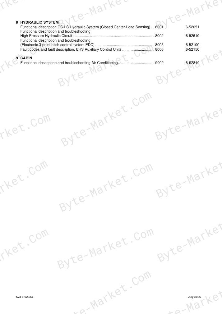
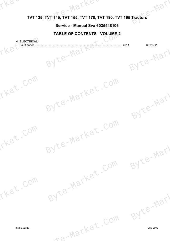
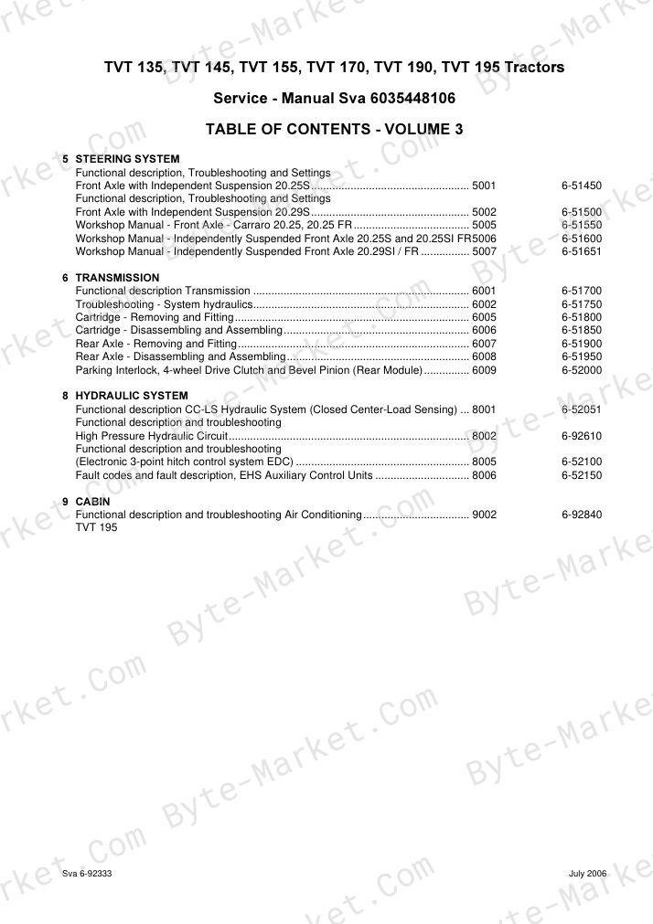
No questions found.