Kubota U17 and U17-3 Specs: Width, Weight and Tight-Access Checks
Kubota U17 and U17-3 Specs: Width, Weight and Tight-Access Checks
A Kubota U17 can narrow its tracks to 990 mm (39 in.) for access and widen them to 1,240 mm (about 49 in.) for work. Those two numbers answer different questions about a backyard job. A machine may fit between the gateposts and still have too little room beyond them to spread its tracks, turn the upper body or put the spoils down. Kubota U17 brochure, p. 3.
Which U17 are you looking at?
Ask the seller or rental desk for the full model shown on the machine. The U.S. brochure identifies its excavator as U17. Kubota Australia lists a U17-3. Their published widths agree, but the specification sheets identify different engine versions and give slightly different operating weights. Keep the model and source beside the figures you use. A sheet headed U17-5 belongs to another machine.
| Published specification | U17, U.S. brochure | U17-3, Kubota Australia |
|---|---|---|
| Track width, narrow / standard | 990 / 1,240 mm | 990 / 1,240 mm |
| Overall length × canopy height | 3,545 × 2,340 mm | 3,545 × 2,340 mm |
| Operating weight | 3,703 lb (1,680 kg), including a 175 lb operator | 1,675 kg (about 3,693 lb), canopy |
| Engine designation | D902-E4 | D902-E3 |
| Maximum digging depth | 2,310 mm (7 ft 7 in.) | 2,310 mm |
The U.S. weight applies to the canopy machine on rubber tracks. The Australian product page gives the canopy weight without the same operator note alongside it. The 5 kg difference alone tells you little about what either machine would weigh on a trailer. U.S. specifications and working range, pp. 7–8 · Australian U17-3 specifications.
Measure the opening where the machine actually passes
A gate sold as one metre wide may have less than a metre of usable space once the latch, hinges and open leaf are in place. Measure the narrowest clear opening with the gate secured open. Check it at track and blade height, then look higher for a projecting post, eave or pipe along the approach. Measure the narrowest point of the whole route, including the turn after the gate.
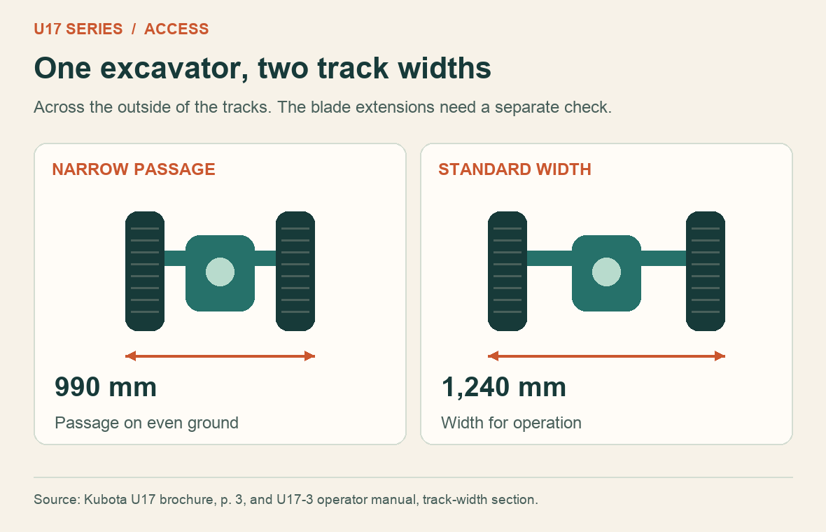
Suppose the clear opening measures exactly 1,000 mm. Subtracting a nominal 990 mm leaves 10 mm in total, or just 5 mm per side if the excavator stays perfectly centred. The arithmetic is a reason to check the actual machine and route with the operator. It provides no allowance for a crooked approach, uneven ground or a bracket projecting past a post.
The U17-3 operator manual reserves the narrow setting for passing through a tight space on even ground. It calls for the standard 1,240 mm setting during work because of tipping risk. It also describes separately repositioning the dozer-blade extensions. Ask where the tracks can be expanded once the machine is through and how the fitted bucket or attachment will clear the entrance. U17-3 operator manual, “Operation of Track Width Change and Dozer”.
Check the space above and beyond the gate
The published canopy height is 2,340 mm, roughly 7 ft 8 in. Measure overhead clearance where the tracks will run. A ramp into a garage or a raised threshold changes the angle of the machine as it passes under the header. For a trailer or enclosed transport vehicle, the relevant measurement starts at the road or trailer floor, depending on the clearance being checked.
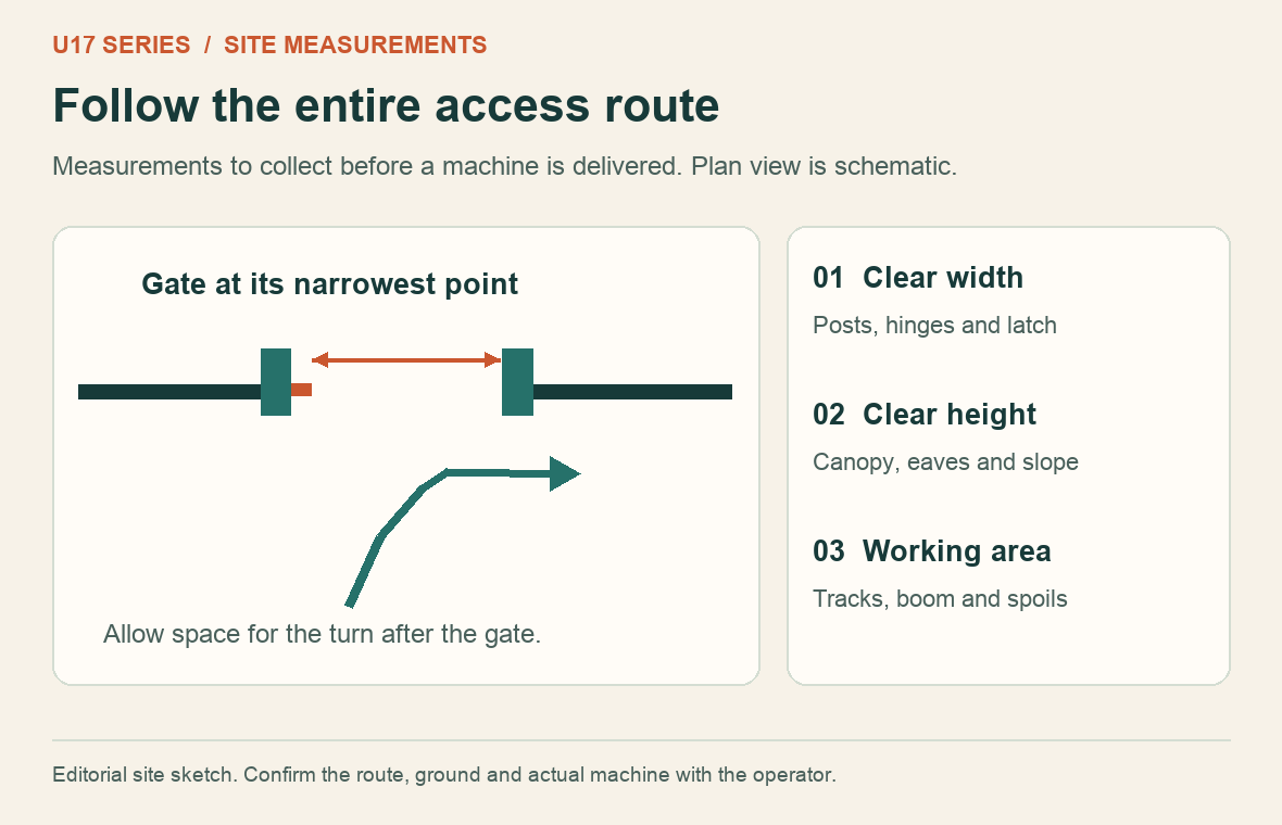
At the excavation, mark the trench, the intended position of the machine and the place for the soil. The U.S. working-range drawing gives a maximum ground-level digging radius of 3,840 mm (12 ft 7 in.) and a maximum depth of 2,310 mm. Each is an extreme on the drawing. A trench that needs both the full horizontal reach and the full depth at the same point requires checking the curve. Even a zero-tail-swing machine needs space for the boom, bucket and load through the turn. U17 working-range drawing, p. 7.
What does the U17 lifting chart say?
Take a single row from the U.S. chart. With the lift point at ground level and 8 ft from the axis of rotation, the over-front entry with the blade down is 0.94. The over-side entry is 0.47. The heading gives thousands of pounds, so those cells read 940 and 470 lb. Turning to the side changes the published value even though the radius and height stay the same.
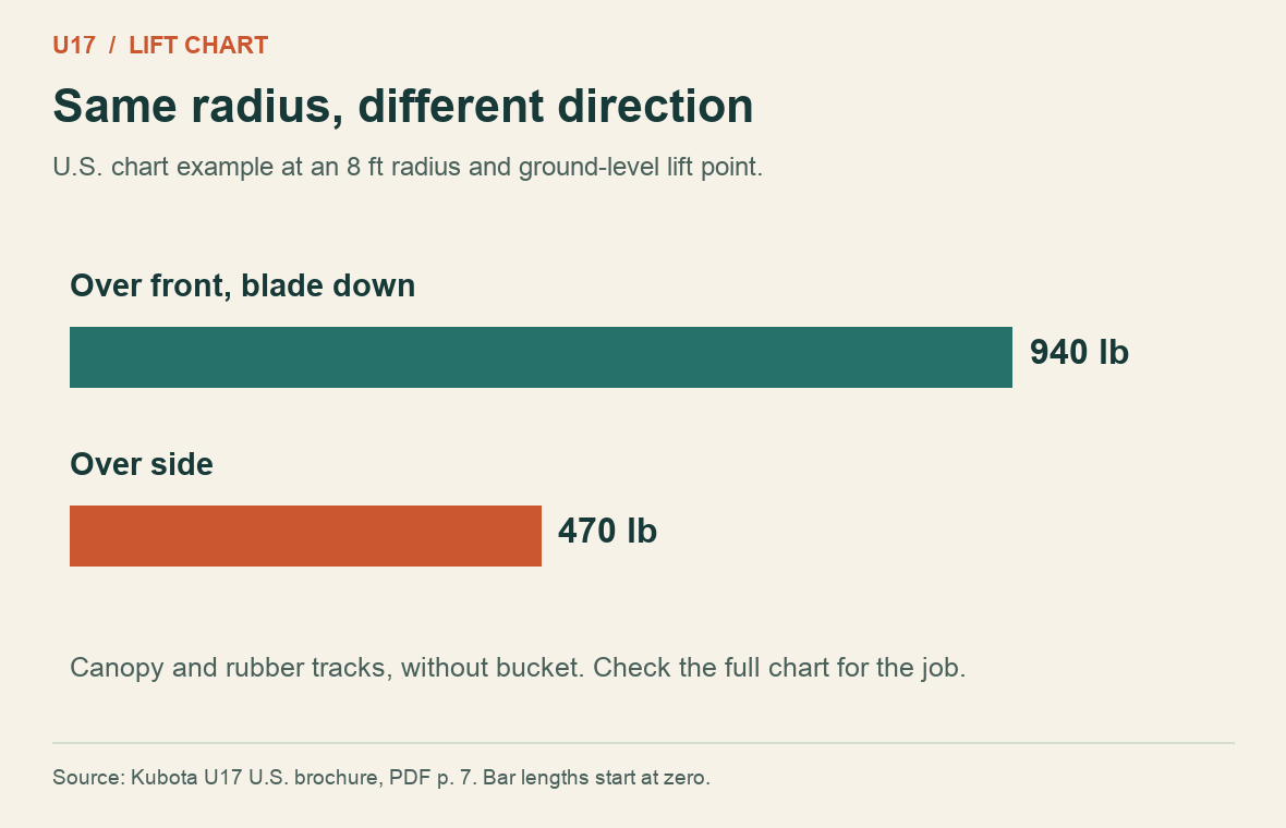
The chart specifies a canopy machine on rubber tracks without a bucket. For an actual lift, use the full chart and operator instructions for the exact machine, radius, height, track setting and direction. Account for the fitted lifting equipment as directed. A bucket breakout-force figure describes digging force and cannot establish the permissible suspended load. Kubota U17 lifting chart, p. 7.
What to send the rental desk or workshop
A short record beats a photograph of the gate alone. Send the machine model, measured opening and overhead clearance, surface and turns, intended digging depth and the attachment you need. For collection, include the equipment travelling on the trailer and confirm its actual loaded weight. For a fault with the variable-width mechanism, record what moved and what stayed still when the symptom occurred.
The workshop can then check the hydraulic circuit for the identified machine. The Byte Market listing covers both U17 and U17-3 and identifies hydraulic diagrams and testing information. U17 and U17-3 workshop manual 97899-61970.
A separate undercarriage issue is track slack. If that is what you are measuring, use the model-specific checking position and gap. How to check Kubota excavator track tension.
Recent Post
-

Why a Kubota Manual May N...
16 Sep, 2026
-
Kubota Tractor Won’t Star...
16 Sep, 2026
-

Kubota DPF Light Flashing...
18 Sep, 2026
-
Kubota Tractor Overheatin...
21 Sep, 2026
-
Kubota Hydraulic Couplers...
22 Sep, 2026
-

Kubota UDT vs Super UDT2:...
23 Sep, 2026
-
Kubota 3-Point Hitch Won'...
24 Sep, 2026
-
Kubota Excavator Track Te...
25 Sep, 2026
-
New Holland540 vs 540E PT...
28 Sep, 2026
-
Kubota BX Mower Cutting U...
29 Sep, 2026
-
Kubota Excavator Controls...
30 Sep, 2026
-
New Holland DEF Storage:...
01 Oct, 2026
-

Kubota Air Filter: When t...
02 Oct, 2026
-
Kubota SVL Standard vs Hi...
06 Oct, 2026
-
New Holland Water in Fuel...
07 Oct, 2026
-
Kubota Loader Float: What...
08 Oct, 2026
-
Kubota HST Tractor Won't...
09 Oct, 2026
-

Kubota 50-Hour Service Ch...
12 Oct, 2026
-
Kubota 4WD Won't Disengag...
13 Oct, 2026
-
Kubota KX040-4 Final Driv...
14 Oct, 2026
-
Kubota PTO Won't Engage?...
15 Oct, 2026
-
How to Check Hydraulic Oi...
16 Oct, 2026
-
Kubota Battery Light Stay...
19 Oct, 2026
-
Kubota Ran Out of Diesel?...
20 Oct, 2026
-
Kubota SVL75-3 Lift Capac...
21 Oct, 2026
-
What Coolant Does a Kubot...
22 Oct, 2026
-
Kubota Engine Oil Level R...
23 Oct, 2026
-
Kubota SVL75-2 DPF Light...
26 Oct, 2026
-
Kubota U55-4 Specs: Weigh...
30 Oct, 2026
-
Kubota M7060 Specs: Weigh...
02 Nov, 2026
-
Kubota L2501 Specs: Weigh...
03 Nov, 2026
-

Kubota BX23S Specs: Weigh...
05 Nov, 2026
-

Kubota D1105 Oil Capacity...
06 Nov, 2026
-
Kubota U17 and U17-3 Spec...
09 Nov, 2026